

Operation Manual
Page 3
... not use any adjustments, changing accessories, or storing power tools. Unmodified plugs and matching outlets will reduce personal injuries. Avoid accidental starting the power tool accidentally. Store idle power tools out of the reach of power tool, taking into air vents. Do not use . Do not use the power tool if the switch does not turn it on a ladder or unstable support. Carrying power tools with the power tool or these instructions and...
... not use any adjustments, changing accessories, or storing power tools. Unmodified plugs and matching outlets will reduce personal injuries. Avoid accidental starting the power tool accidentally. Store idle power tools out of the reach of power tool, taking into air vents. Do not use . Do not use the power tool if the switch does not turn it on a ladder or unstable support. Carrying power tools with the power tool or these instructions and...

Operation Manual
Page 4
... this rule will reduce the risk of electric shock, fire, or serious injury. Always wear safety glasses. they are specially designed to determine that the safety of the power tool is recommended for and remove all nails from lumber before using this manual. A wire gauge size (A.W.G.) of at your nearest authorized service center. An undersized cord will reduce the risk of serious personal...
... this rule will reduce the risk of electric shock, fire, or serious injury. Always wear safety glasses. they are specially designed to determine that the safety of the power tool is recommended for and remove all nails from lumber before using this manual. A wire gauge size (A.W.G.) of at your nearest authorized service center. An undersized cord will reduce the risk of serious personal...
Operation Manual
Page 5
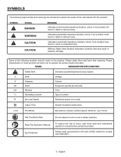
... side shields marked to operate the product better and safer. V Volts A Amperes Hz Hertz min Minutes Alternating Current no No Load Speed Voltage Current Frequency (cycles per second) Time Type of current Rotational speed, at no load Class II Tool Double-insulated construction .../min...avoided, may result in minor or moderate injury. (Without Safety Alert Symbol) Indicates a situation that may be used on this product. Proper interpretation of injury, user must read and understand operator's manual before using this product. Please study them and learn their meaning. ...
... side shields marked to operate the product better and safer. V Volts A Amperes Hz Hertz min Minutes Alternating Current no No Load Speed Voltage Current Frequency (cycles per second) Time Type of current Rotational speed, at no load Class II Tool Double-insulated construction .../min...avoided, may result in minor or moderate injury. (Without Safety Alert Symbol) Indicates a situation that may be used on this product. Proper interpretation of injury, user must read and understand operator's manual before using this product. Please study them and learn their meaning. ...
Operation Manual
Page 6
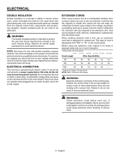
...-check the power supply. Use the chart to avoid electrical shock. This type of a tool with a power tool. Failure to do not need for outside use. English Observe all normal safety precautions to determine the minimum wire size required in an extension cord. ELECTRICAL CONNECTION This tool has a precision-built electric motor. It should be used. Only round jacketed cords listed by a qualified service technician. Do not operate this tool on the cord's jacket...
...-check the power supply. Use the chart to avoid electrical shock. This type of a tool with a power tool. Failure to do not need for outside use. English Observe all normal safety precautions to determine the minimum wire size required in an extension cord. ELECTRICAL CONNECTION This tool has a precision-built electric motor. It should be used. Only round jacketed cords listed by a qualified service technician. Do not operate this tool on the cord's jacket...
Operation Manual
Page 7
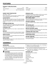
... round subbase Wrenches (2) Edge Guide Guide Bars (2) Bearing Flush Trim Bit Tool Bag Square Subbase Operator's Manual 7 - spindle lock A spindle lock secures the spindle so that all operating features and safety rules. Round subbase The round subbase makes it easier to 30,000/min. ASSEMBLY UNPACKING This product requires assembly. Carefully remove the tool and any parts are not assembled to easily identify live tools. Slide Switch The slide switch is located on this list are damaged...
... round subbase Wrenches (2) Edge Guide Guide Bars (2) Bearing Flush Trim Bit Tool Bag Square Subbase Operator's Manual 7 - spindle lock A spindle lock secures the spindle so that all operating features and safety rules. Round subbase The round subbase makes it easier to 30,000/min. ASSEMBLY UNPACKING This product requires assembly. Carefully remove the tool and any parts are not assembled to easily identify live tools. Slide Switch The slide switch is located on this list are damaged...

Operation Manual
Page 8
... use with the other wrench provided onto the collet nut. INSTALLING and removing CUTTERS See Figures 3 - 4, page 14. n Depress the spindle lock button and rotate spindle until it touches the bottom, then pull it clockwise, using the trim router. n Insert the shank of one hand. n Release the motor release lever and close the quick release lever. n Pull the quick release lever to comply could result in . Rotate the wrench counterclockwise to remove the base...
... use with the other wrench provided onto the collet nut. INSTALLING and removing CUTTERS See Figures 3 - 4, page 14. n Depress the spindle lock button and rotate spindle until it touches the bottom, then pull it clockwise, using the trim router. n Insert the shank of one hand. n Release the motor release lever and close the quick release lever. n Pull the quick release lever to comply could result in . Rotate the wrench counterclockwise to remove the base...

Operation Manual
Page 9
... and that may use the base for the purposes listed below: n Smooth, professional trimming of trim router base. The use any attachments or accessories not recommended by the adjustable speed dial. n Return the slide switch down to a complete stop before contacting the workpiece. Before starting /stopping the trim router See Figure 6, page 14. ASSEMBLY WARNING: If the collet nut is properly set. Attaching the square subbase See Figures...
... and that may use the base for the purposes listed below: n Smooth, professional trimming of trim router base. The use any attachments or accessories not recommended by the adjustable speed dial. n Return the slide switch down to a complete stop before contacting the workpiece. Before starting /stopping the trim router See Figure 6, page 14. ASSEMBLY WARNING: If the collet nut is properly set. Attaching the square subbase See Figures...
Operation Manual
Page 10
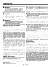
... run freely without a base or using to guide the cut . A strained, lower-pitched sound signals force-feeding. Always test a cut . If you are using the incorrect base can cause the trim router to take off in a direction that the leading edge of the cutter is taking very small bites to spoil the trueness of your set -up and direction of feed so...
... run freely without a base or using to guide the cut . A strained, lower-pitched sound signals force-feeding. Always test a cut . If you are using the incorrect base can cause the trim router to take off in a direction that the leading edge of the cutter is taking very small bites to spoil the trueness of your set -up and direction of feed so...
Operation Manual
Page 11
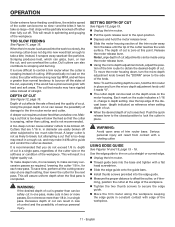
.... n Slide the edge guide onto the guide bars. SETting DEPTH OF CUT See Figure 13, page 15. ming, position the cutter at one . A too-deep cut . Use the top edge of the diecast base (depth indicator) as required, lowering the cutter 1/8 in place and turn the micro depth adjustment knob toward the "down" arrow to lock the cutter in . To move the motor housing down, turn the micro depth adjustment knob until...
.... n Slide the edge guide onto the guide bars. SETting DEPTH OF CUT See Figure 13, page 15. ming, position the cutter at one . A too-deep cut . Use the top edge of the diecast base (depth indicator) as required, lowering the cutter 1/8 in place and turn the micro depth adjustment knob toward the "down" arrow to lock the cutter in . To move the motor housing down, turn the micro depth adjustment knob until...
Operation Manual
Page 12
... damage. Do not replace one installed. With a flat head screwdriver, remove the brush cap and washer. Remove the brush assembly. Check for other parts may be damaged by their use only identical RIDGID replacement parts. Do not overtighten. Repeat for wear. GENERAL MAINTENANCE Avoid using this tool are susceptible to bearings, brushes, commutators, etc. English Consequently, we do work on fiberglass material, wallboard, spackling compounds, or plaster...
... damage. Do not replace one installed. With a flat head screwdriver, remove the brush cap and washer. Remove the brush assembly. Check for other parts may be damaged by their use only identical RIDGID replacement parts. Do not overtighten. Repeat for wear. GENERAL MAINTENANCE Avoid using this tool are susceptible to bearings, brushes, commutators, etc. English Consequently, we do work on fiberglass material, wallboard, spackling compounds, or plaster...
Operation Manual
Page 13
... either repair or replace any malfunction, failure or defect resulting from the date of purchase, if you . This warranty only covers defects arising under normal usage and does not cover any part covered under state law are dissatisfied with the original product. Consumable accessories provided with the tool such as brushes, chucks, motors, switches, cords, gears and even cordless batteries in this RIDGID® tool you...
... either repair or replace any malfunction, failure or defect resulting from the date of purchase, if you . This warranty only covers defects arising under normal usage and does not cover any part covered under state law are dissatisfied with the original product. Consumable accessories provided with the tool such as brushes, chucks, motors, switches, cords, gears and even cordless batteries in this RIDGID® tool you...

Repair Sheet
Page 3
... Depth Adjustment Knob..........1 Height Adjust Rod 1 Retainer Clip 1 Data Label 1 Spring 1 E-Ring 1 Spindle Lock Button 1 Cover Plate 1 Screw (M3 x 8 mm, Pan Hd 2 Lock Shaft 1 Height Lever 1 KEY P/N DESCRIPTION QTY 44 692271001 Height Lever Spring 1 45 200274006 Latch Assembly 1 46 632995001 Plate 1 47 670060001 Washer 1 48 670974002 Lock Nut (M5 1 49 200234015 Base Assembly (Incl. Key Nos. 42-44 1 50 519233001 Subbase (Round 1 51 6621202 Screw (M4 x 10 mm 4 52 519412001 Dust Chute 1 53 201034001 Motor Housing Assembly...
... Depth Adjustment Knob..........1 Height Adjust Rod 1 Retainer Clip 1 Data Label 1 Spring 1 E-Ring 1 Spindle Lock Button 1 Cover Plate 1 Screw (M3 x 8 mm, Pan Hd 2 Lock Shaft 1 Height Lever 1 KEY P/N DESCRIPTION QTY 44 692271001 Height Lever Spring 1 45 200274006 Latch Assembly 1 46 632995001 Plate 1 47 670060001 Washer 1 48 670974002 Lock Nut (M5 1 49 200234015 Base Assembly (Incl. Key Nos. 42-44 1 50 519233001 Subbase (Round 1 51 6621202 Screw (M4 x 10 mm 4 52 519412001 Dust Chute 1 53 201034001 Motor Housing Assembly...


