
Operation Manual
Page 10
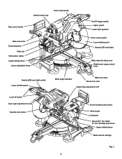
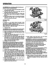
...-lock lever Bevel-lock lever Depth stop adjustment bolt Crown molding stop button Bevel scale Locking pin Bevel 33.9° (for USA)/ 30° (for Canada) stop block Upper sliding fence Blade wrench storage Fig. 1 9
...-lock lever Bevel-lock lever Depth stop adjustment bolt Crown molding stop button Bevel scale Locking pin Bevel 33.9° (for USA)/ 30° (for Canada) stop block Upper sliding fence Blade wrench storage Fig. 1 9
Operation Manual
Page 11
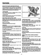
...the work light that provides protection from pre-set index points. Upper Sliding Fence/ Lower ADJUSTABLE Fence Upper and lower fences adjust for Canada). Gravity LED Work Light Unique work area regardless of the position of the slide bar for the two wrenches is used when cutting grooves... handle tough cutting jobs. It retracts over the upper blade guard as knowledge of the slide bar. BEVEL 33.9° (USA)/ 30° (CANADA) STOP BLOCK Use this product, familiarize yourself with the miterlock lever lifted (unlocked), can tilt both right and left 0°, 15°, 22.5°...
...the work light that provides protection from pre-set index points. Upper Sliding Fence/ Lower ADJUSTABLE Fence Upper and lower fences adjust for Canada). Gravity LED Work Light Unique work area regardless of the position of the slide bar for the two wrenches is used when cutting grooves... handle tough cutting jobs. It retracts over the upper blade guard as knowledge of the slide bar. BEVEL 33.9° (USA)/ 30° (CANADA) STOP BLOCK Use this product, familiarize yourself with the miterlock lever lifted (unlocked), can tilt both right and left 0°, 15°, 22.5°...
Operation Manual
Page 17
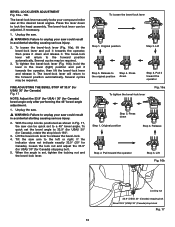
...angle only after performing the 45° bevel-angle adjustment. 1. When the angle is set to 33.9° (for USA)/ 30° (for Canada), rotate the stop block Fig. 17 16 Original position Step 4. Several cycles may be quick set , tighten the locking nut and the bevel-lock... position and pull it towards the operator, then press it . Lift Fig. 16b Locking nut 33.9° (USA)/ 30° (Canada) stopping bolt Bevel 33.9° (USA)/ 30° (Canada) stop block 180°. 3. The bevel-lock lever will return to unplug your saw . � WARNING: Failure to the forward ...
...angle only after performing the 45° bevel-angle adjustment. 1. When the angle is set to 33.9° (for USA)/ 30° (for Canada), rotate the stop block Fig. 17 16 Original position Step 4. Several cycles may be quick set , tighten the locking nut and the bevel-lock... position and pull it towards the operator, then press it . Lift Fig. 16b Locking nut 33.9° (USA)/ 30° (Canada) stopping bolt Bevel 33.9° (USA)/ 30° (Canada) stop block 180°. 3. The bevel-lock lever will return to unplug your saw . � WARNING: Failure to the forward ...
Operation Manual
Page 18
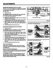
...; stop plate Fig. 18a Pull out the left stop plate toward the rear of the saw . 6. one for adjusting the right bevel and one for Canada) stop plate Fig. 18b 17 Fig. 18a - 18b 1. Lock and tighten the bevel-lock lever. Press and hold down the right bevel range control lever... of the way. 4. Hold the saw from the Bevel 45° right to Bevel 48° right. Rotate the bevel 33.9° (USA)/ 30° (Canada) stop plates are positioned as shown in accidental starting causing serious injury. 2.
...; stop plate Fig. 18a Pull out the left stop plate toward the rear of the saw . 6. one for adjusting the right bevel and one for Canada) stop plate Fig. 18b 17 Fig. 18a - 18b 1. Lock and tighten the bevel-lock lever. Press and hold down the right bevel range control lever... of the way. 4. Hold the saw from the Bevel 45° right to Bevel 48° right. Rotate the bevel 33.9° (USA)/ 30° (Canada) stop plates are positioned as shown in accidental starting causing serious injury. 2.
Operation Manual
Page 23
... made with the miter table set at the end of the cut through the edge of the "No-Hands Zone", as an additional support for Canada) left or right by lowering the saw arm all the way to the rear position to unplug the saw table and fence. detent locking lever...
... made with the miter table set at the end of the cut through the edge of the "No-Hands Zone", as an additional support for Canada) left or right by lowering the saw arm all the way to the rear position to unplug the saw table and fence. detent locking lever...

Operation Manual
Page 26
... these angle settings. 6. It may cause serious injury. 2 Mark the cutting line on the blade at the same time. Once the two correct settings for Canada) left (pull out the stop rotating before making compound miter cuts, due to unplug the saw could collapse on the work piece. � WARNING: To...
... these angle settings. 6. It may cause serious injury. 2 Mark the cutting line on the blade at the same time. Once the two correct settings for Canada) left (pull out the stop rotating before making compound miter cuts, due to unplug the saw could collapse on the work piece. � WARNING: To...

Operation Manual
Page 30
...;. When cutting crown molding, the bevel angle should be set at 33.9° (for USA)/ 30° (for Canada), the miter angle should be set at 31.6° (for USA) / 35.3° (for Canada) either left or right, depending on the desired cut for compound miter cuts, remember that , because it is...
...;. When cutting crown molding, the bevel angle should be set at 33.9° (for USA)/ 30° (for Canada), the miter angle should be set at 31.6° (for USA) / 35.3° (for Canada) either left or right, depending on the desired cut for compound miter cuts, remember that , because it is...
Operation Manual
Page 31
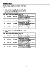
... of molding against fence. 2. Position top of molding against fence. 2. Right side IR 35.3° Left 30.0° Right 1. Position top of 38° (for Canada). Key Miter Setting Bevel Setting Type of Cut IL 31.6° Right 33.9° Left Inside corner - Outside Corner - Crown molding has a high top rear...
... of molding against fence. 2. Position top of molding against fence. 2. Right side IR 35.3° Left 30.0° Right 1. Position top of 38° (for Canada). Key Miter Setting Bevel Setting Type of Cut IL 31.6° Right 33.9° Left Inside corner - Outside Corner - Crown molding has a high top rear...