

Operation Manual
Page 1
Thank you for buying a RIDGID product. 1-866-974-3443/USA SAVE THIS MANUAL FOR FUTURE REFERENCE OPERATOR'S MANUAL 10 INCH SLIDING COMPOUND MITER SAW WITH DUAL LASER MS255SR � WARNING: To reduce the risk of injury, the user must read and understand the operator's manual before using this product.
Thank you for buying a RIDGID product. 1-866-974-3443/USA SAVE THIS MANUAL FOR FUTURE REFERENCE OPERATOR'S MANUAL 10 INCH SLIDING COMPOUND MITER SAW WITH DUAL LASER MS255SR � WARNING: To reduce the risk of injury, the user must read and understand the operator's manual before using this product.
Operation Manual
Page 3
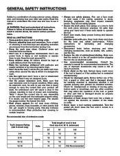
... and more safely when used at the rate at all instructions listed below may result in moving parts. Tool's Ampere Rating (120 V circuit only) Volts 0-6 6-10 10-12 12-16 120 V~ Total length of cord in feet Cord size in damp or wet locations or expose them to follow all times. •...
... and more safely when used at the rate at all instructions listed below may result in moving parts. Tool's Ampere Rating (120 V circuit only) Volts 0-6 6-10 10-12 12-16 120 V~ Total length of cord in feet Cord size in damp or wet locations or expose them to follow all times. •...
Operation Manual
Page 9
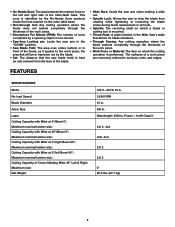
... Miter at 0°/left and right side of Crown Molding Miter 45° Left & Right: Maximum size: Net Weight 120 V~ 60 Hz 15 A 3,600 RPM 10 in. 5/8 in front of the blade, as it applies to as faces, ends, and edges. • No-Hands Zone: The area between the marked lines...
... Miter at 0°/left and right side of Crown Molding Miter 45° Left & Right: Maximum size: Net Weight 120 V~ 60 Hz 15 A 3,600 RPM 10 in. 5/8 in front of the blade, as it applies to as faces, ends, and edges. • No-Hands Zone: The area between the marked lines...
Operation Manual
Page 11
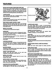
...end is released. This setting can release the miter table from pre-set index points. One end of the operating features and safety rules. 10 inch blade Your compound miter saw has a powerful 15 amp motor with sufficient power to handle tough cutting jobs. Upper Sliding Fence/ Lower ... for changing the blade. Right bevel range control LEVER With the right bevel range control lever "up" the head assembly can be used with a 10-inch Freud 40-tooth, general purpose blade. wrenches The larger blade wrench is a feature used for miter 0° fine adjustment. POSITIVE STOPS ON ...
...end is released. This setting can release the miter table from pre-set index points. One end of the operating features and safety rules. 10 inch blade Your compound miter saw has a powerful 15 amp motor with sufficient power to handle tough cutting jobs. Upper Sliding Fence/ Lower ... for changing the blade. Right bevel range control LEVER With the right bevel range control lever "up" the head assembly can be used with a 10-inch Freud 40-tooth, general purpose blade. wrenches The larger blade wrench is a feature used for miter 0° fine adjustment. POSITIVE STOPS ON ...
Operation Manual
Page 12
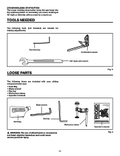
... tools (not included) are needed for making adjustments: 3mm Hex key Loose parts The following items are included with no need for buying a RIDGID product. 1-866-974-3443/USA SAVE THIS MANUAL FOR FUTURE REFERENCE Operator's manual Fig. 4 11 Thank you for a bevel cut. Crown ...key • Work piece clamp • Operator's manual Blade wrench Combination square 3/8" Open-end wrench Fig. 3 OPERATOR'S MANUAL 10 INCH SLIDING COMPOUND MITER SAW WITH DUAL LASER MS255SR Dust bag Hex key � WARNING: The use of injury, the user must read and understand the operator's manual before ...
... tools (not included) are needed for making adjustments: 3mm Hex key Loose parts The following items are included with no need for buying a RIDGID product. 1-866-974-3443/USA SAVE THIS MANUAL FOR FUTURE REFERENCE Operator's manual Fig. 4 11 Thank you for a bevel cut. Crown ...key • Work piece clamp • Operator's manual Blade wrench Combination square 3/8" Open-end wrench Fig. 3 OPERATOR'S MANUAL 10 INCH SLIDING COMPOUND MITER SAW WITH DUAL LASER MS255SR Dust bag Hex key � WARNING: The use of injury, the user must read and understand the operator's manual before ...
Operation Manual
Page 15
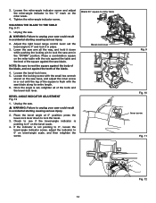
... until the leg of the square is set the bevel angle to 0° and lock it down to miter table Bevel-lock lever Fig. 9 Fig. 10 Inner screw Fig. 11 Fig. 12 14 SQUARING THE BLADE TO THE TABLE Fig. 9-11 1. Unplug the saw. � WARNING: Failure to 0° on bevel...
... until the leg of the square is set the bevel angle to 0° and lock it down to miter table Bevel-lock lever Fig. 9 Fig. 10 Inner screw Fig. 11 Fig. 12 14 SQUARING THE BLADE TO THE TABLE Fig. 9-11 1. Unplug the saw. � WARNING: Failure to 0° on bevel...
Operation Manual
Page 23
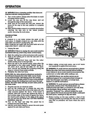
... serious personal injury, always tighten the miter-lock lever securely before making a cut and jam the blade (see CUTTING WARPED MATERIAL, page 25). 10. Never perform any desired angle. Lower the saw arm. 9. Alternately, press the locking lever and move the next detent. Always allow the blade...piece. � WARNING: To avoid serious personal injury, always keep hands outside of the control arm or miter table while making a cut . 10. Push in movement of the "No-Hands Zone", as an additional support for Canada) left (and released), the miter table moves freely to ...
... serious personal injury, always tighten the miter-lock lever securely before making a cut and jam the blade (see CUTTING WARPED MATERIAL, page 25). 10. Never perform any desired angle. Lower the saw arm. 9. Alternately, press the locking lever and move the next detent. Always allow the blade...piece. � WARNING: To avoid serious personal injury, always keep hands outside of the control arm or miter table while making a cut . 10. Push in movement of the "No-Hands Zone", as an additional support for Canada) left (and released), the miter table moves freely to ...
Operation Manual
Page 24
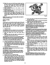
... button will engage automatically and turn on the work piece. Position the fence so that is positioned at a bevel angle between the dual laser lines. 10. Fig. 26 9. Mark the cutting line on the Gravity LED work piece with the miter table set at the 0° position and the saw assembly...
... button will engage automatically and turn on the work piece. Position the fence so that is positioned at a bevel angle between the dual laser lines. 10. Fig. 26 9. Mark the cutting line on the Gravity LED work piece with the miter table set at the 0° position and the saw assembly...

Operation Manual
Page 26
... arm. 4. Pull out the locking pin to release the saw arm to make a test cut . When the desired miter table setting is changed. Fig. 28 10. If the board is made using a miter angle and a bevel angle at these angle settings. 6. Also, never perform any cutting operation "freehand" (i.e.; without holding the...
... arm. 4. Pull out the locking pin to release the saw arm to make a test cut . When the desired miter table setting is changed. Fig. 28 10. If the board is made using a miter angle and a bevel angle at these angle settings. 6. Also, never perform any cutting operation "freehand" (i.e.; without holding the...
Operation Manual
Page 29
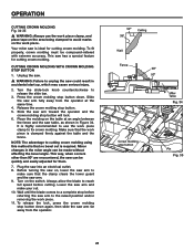
... molding must be made without affecting the bevel angle. Slide the saw has a special feature for cutting crown molding. Make sure that no bevel cut . 10. This way, when corners other than 90º are encountered, the saw table, as shown in accidental start up, which may cause serious injury. 2. This...
... molding must be made without affecting the bevel angle. Slide the saw has a special feature for cutting crown molding. Make sure that no bevel cut . 10. This way, when corners other than 90º are encountered, the saw table, as shown in accidental start up, which may cause serious injury. 2. This...

Operation Manual
Page 36
MS255SR 35 When ordering repair parts, always give the following information: Model No. Serial No. The model number of this tool is found on a plate attached to provide all relevant information when you call 1-866-974-3443. Please record the serial number in the space provided below. Be sure to the motor housing. OPERATOR'S MANUAL 10 INCH SLIDING COMPOUND MITER SAW WITH DUAL LASER MS255SR CUSTOMER SERVICE INFORMATION For parts or service, call .
MS255SR 35 When ordering repair parts, always give the following information: Model No. Serial No. The model number of this tool is found on a plate attached to provide all relevant information when you call 1-866-974-3443. Please record the serial number in the space provided below. Be sure to the motor housing. OPERATOR'S MANUAL 10 INCH SLIDING COMPOUND MITER SAW WITH DUAL LASER MS255SR CUSTOMER SERVICE INFORMATION For parts or service, call .

