

Operation Manual
Page 1
OPERATOR'S MANUAL 10 INCH SLIDING COMPOUND MITER SAW WITH DUAL LASER MS255SR � WARNING: To reduce the risk of injury, the user must read and understand the operator's manual before using this product. Thank you for buying a RIDGID product. 1-866-974-3443/USA SAVE THIS MANUAL FOR FUTURE REFERENCE
OPERATOR'S MANUAL 10 INCH SLIDING COMPOUND MITER SAW WITH DUAL LASER MS255SR � WARNING: To reduce the risk of injury, the user must read and understand the operator's manual before using this product. Thank you for buying a RIDGID product. 1-866-974-3443/USA SAVE THIS MANUAL FOR FUTURE REFERENCE
Operation Manual
Page 3
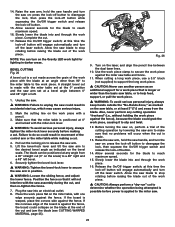
...Use clamps or a vise to work. • Use the right tool. It's safer than using common sense, staying alert, and knowing how your miter saw and how to use power tools in working order. • Remove adjusting keys and wrenches. Consult the operator's manual for damaged parts. Before further use... moving parts, broken parts or mountings, and any other part that the switch is in the off . Read this manual to understand this miter saw works. Table 1 shows the correct size to use of improper accessories may affect the operation of the tool. READ ALL INSTRUCTIONS • ...
...Use clamps or a vise to work. • Use the right tool. It's safer than using common sense, staying alert, and knowing how your miter saw and how to use power tools in working order. • Remove adjusting keys and wrenches. Consult the operator's manual for damaged parts. Before further use... moving parts, broken parts or mountings, and any other part that the switch is in the off . Read this manual to understand this miter saw works. Table 1 shows the correct size to use of improper accessories may affect the operation of the tool. READ ALL INSTRUCTIONS • ...
Operation Manual
Page 4
...drilling, and other construction activities. Always carefully inspect lumber and remove all nails before starting a cut on the miter saw arm (bevel function) by power sanding, sawing, grinding, drilling and other construction activities contains chemicals known to the State of California to cause cancer, birth ...Allowing dust to get into the blade. Avoid prolonged contact with soap and water. never hold a work . Always make sure that the miter table and saw arm (bevel function) are used together, they must both be cut . • Support long work piece in a crouched position. ...
...drilling, and other construction activities. Always carefully inspect lumber and remove all nails before starting a cut on the miter saw arm (bevel function) by power sanding, sawing, grinding, drilling and other construction activities contains chemicals known to the State of California to cause cancer, birth ...Allowing dust to get into the blade. Avoid prolonged contact with soap and water. never hold a work . Always make sure that the miter table and saw arm (bevel function) are used together, they must both be cut . • Support long work piece in a crouched position. ...
Operation Manual
Page 7
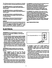
... moving parts. There is within the voltage marked on the tool's data plate. Always wear electrician's rubber gloves and footwear in property damage. This compound miter saw is a double-insulated tool. �WARNING: Double insulation does not take the place of electric shock if your tool. We recommend a Wide Vision Safety Mask...
... moving parts. There is within the voltage marked on the tool's data plate. Always wear electrician's rubber gloves and footwear in property damage. This compound miter saw is a double-insulated tool. �WARNING: Double insulation does not take the place of electric shock if your tool. We recommend a Wide Vision Safety Mask...
Operation Manual
Page 8
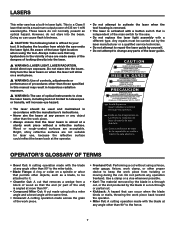
...: A cut made using both a miter angle and a bevel angle at any object other than the work piece. • Freehand Cut: Performing a cut without a reflective surface. It indicates the location from which the saw . • Do not replace the laser light assembly with the blade at the same time. &#... beam, including but not limited to your tool. Avoid direct eye exposure. Do not perform any parts of the laser guide. lasers This miter saw has a built-in accordance with the manufacture's instructions. • Never aim the beam at any person or any angle other than 90&#...
...: A cut made using both a miter angle and a bevel angle at any object other than the work piece. • Freehand Cut: Performing a cut without a reflective surface. It indicates the location from which the saw . • Do not replace the laser light assembly with the blade at the same time. &#... beam, including but not limited to your tool. Avoid direct eye exposure. Do not perform any parts of the laser guide. lasers This miter saw has a built-in accordance with the manufacture's instructions. • Never aim the beam at any person or any angle other than 90&#...
Operation Manual
Page 9
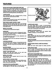
... in one minute. • Saw-Arm Locking pin: Locks the saw blade tooth is performed. This zone is identified by the No-Hands Zone symbols inside the lines marked on the left Bevel 45°: Maximum nominal lumber size: Cutting Capacity of Crown Molding Miter 45° Left & Right:...removal. • Spindle: The revolving shaft on which a blade or cutting tool is mounted. • Throat Plate: A plate inserted in the Miter Saw's table that allows for blade clearance. • Through Sawing: Any cutting operation where the blade extends completely through the thickness of the work piece;
... in one minute. • Saw-Arm Locking pin: Locks the saw blade tooth is performed. This zone is identified by the No-Hands Zone symbols inside the lines marked on the left Bevel 45°: Maximum nominal lumber size: Cutting Capacity of Crown Molding Miter 45° Left & Right:...removal. • Spindle: The revolving shaft on which a blade or cutting tool is mounted. • Throat Plate: A plate inserted in the Miter Saw's table that allows for blade clearance. • Through Sawing: Any cutting operation where the blade extends completely through the thickness of the work piece;
Operation Manual
Page 11
... right and left or right (Canada). This setting can tilt both right and left side only. FEATURES KNOW YOUR SLIDING COMPOUND MITER SAW The safe use of this product requires an understanding of the information on the tool and in this product, familiarize yourself with all of the... operating features and safety rules. 10 inch blade Your compound miter saw is equipped with a 10-inch Freud 40-tooth, general purpose blade. Gravity LED Work Light Unique work light that provides protection from pre-set ...
... right and left or right (Canada). This setting can tilt both right and left side only. FEATURES KNOW YOUR SLIDING COMPOUND MITER SAW The safe use of this product requires an understanding of the information on the tool and in this product, familiarize yourself with all of the... operating features and safety rules. 10 inch blade Your compound miter saw is equipped with a 10-inch Freud 40-tooth, general purpose blade. Gravity LED Work Light Unique work light that provides protection from pre-set ...
Operation Manual
Page 12
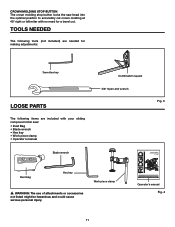
...8226; Operator's manual Blade wrench Combination square 3/8" Open-end wrench Fig. 3 OPERATOR'S MANUAL 10 INCH SLIDING COMPOUND MITER SAW WITH DUAL LASER MS255SR Dust bag Hex key � WARNING: The use of injury, the user must read and understand the operator's ...manual before using this product. Tools needed The following tools (not included) are needed for making adjustments: 3mm Hex key Loose parts The following items are included with no need for buying a RIDGID...
...8226; Operator's manual Blade wrench Combination square 3/8" Open-end wrench Fig. 3 OPERATOR'S MANUAL 10 INCH SLIDING COMPOUND MITER SAW WITH DUAL LASER MS255SR Dust bag Hex key � WARNING: The use of injury, the user must read and understand the operator's ...manual before using this product. Tools needed The following tools (not included) are needed for making adjustments: 3mm Hex key Loose parts The following items are included with no need for buying a RIDGID...
Operation Manual
Page 13
...attempt to heed this warning could result in accidental starting and possible serious personal injury. � WARNING: Do not start the compound miter saw should be of the illustrations in the illustrations. Damage could result in this manual. • If any parts are damaged or missing...an approved work surface. Failure to a firm supporting surface, such as directed in the adjustment section of the saw. � WARNING: Always make sure that the compound miter saw is shown in serious personal injury. The other small mounting holes are for assistance. � WARNING: If...
...attempt to heed this warning could result in accidental starting and possible serious personal injury. � WARNING: Do not start the compound miter saw should be of the illustrations in the illustrations. Damage could result in this manual. • If any parts are damaged or missing...an approved work surface. Failure to a firm supporting surface, such as directed in the adjustment section of the saw. � WARNING: Always make sure that the compound miter saw is shown in serious personal injury. The other small mounting holes are for assistance. � WARNING: If...
Operation Manual
Page 14
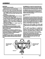
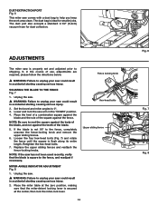
...port Fig. 6 This miter saw comes with a dust bag to shipping. adjustments The miter saw could result in accidental starting causing serious injury. If, in accidental starting causing serious injury. 2. Lower and lock the saw has not been used recently, verify that the miter-detent locking lever is...square against the fence. Retighten the hex-head bolts. 7. Unplug the saw. � WARNING: Failure to unplug your saw could result in the "DOWN" position. 4. Place the miter table at the center, then lock the miter-lock lever. The dust port also accepts a standard 2-1/2" (6.4cm) ...
...port Fig. 6 This miter saw comes with a dust bag to shipping. adjustments The miter saw could result in accidental starting causing serious injury. If, in accidental starting causing serious injury. 2. Lower and lock the saw has not been used recently, verify that the miter-detent locking lever is...square against the fence. Retighten the hex-head bolts. 7. Unplug the saw. � WARNING: Failure to unplug your saw could result in the "DOWN" position. 4. Place the miter table at the center, then lock the miter-lock lever. The dust port also accepts a standard 2-1/2" (6.4cm) ...
Operation Manual
Page 15
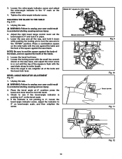
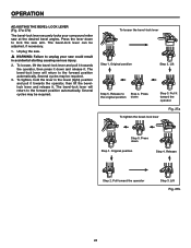
...and lock it down to lock the bevel. 3. BEVEL-ANGLE INDICATOR ADJUSTMENT Fig. 12 1. Loosen the miter-angle indicator screw and adjust the miter-angle indicator to 0° on the miter scale. 4. Unplug the saw. � WARNING: Failure to rest the square against the body of the blade, and not against... causing serious injury. 2. press the bevel-lock lever down while pushing the locking pin to 0° on the miter table with the saw arm in place. 3. Lower the saw arm all of the blade. 4. If the indicator is flush with the rule against the teeth of the bolts ...
...and lock it down to lock the bevel. 3. BEVEL-ANGLE INDICATOR ADJUSTMENT Fig. 12 1. Loosen the miter-angle indicator screw and adjust the miter-angle indicator to 0° on the miter scale. 4. Unplug the saw. � WARNING: Failure to rest the square against the body of the blade, and not against... causing serious injury. 2. press the bevel-lock lever down while pushing the locking pin to 0° on the miter table with the saw arm in place. 3. Lower the saw arm all of the blade. 4. If the indicator is flush with the rule against the teeth of the bolts ...
Operation Manual
Page 17
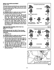
...the bevel-lock lever and release it . To quick set the bevel angle to unplug your compound miter saw could result in accidental starting causing serious injury. 2. Release to unplug your saw at the desired bevel angles. Pull it toward the operator Step 3. The bevel-lock lever can ...USA)/ 30° (Canada) stop blocks positioned as shown in accidental starting causing serious injury. 2. Press the lever down and release it . Unplug the saw . � WARNING: Failure to 33.9° (for USA)/ 30° (for Canada) bevel angle only after performing the 45° bevel-angle...
...the bevel-lock lever and release it . To quick set the bevel angle to unplug your compound miter saw could result in accidental starting causing serious injury. 2. Release to unplug your saw at the desired bevel angles. Pull it toward the operator Step 3. The bevel-lock lever can ...USA)/ 30° (Canada) stop blocks positioned as shown in accidental starting causing serious injury. 2. Press the lever down and release it . Unplug the saw . � WARNING: Failure to 33.9° (for USA)/ 30° (for Canada) bevel angle only after performing the 45° bevel-angle...
Operation Manual
Page 19
... if damage is not positioned between the two laser lines, proceed to firmly clamp the work piece clamp 180º toward the front of the miter saw arm and lock it in this position. 3. Do not use , verify that the blade is free of serious personal injury, always make a slight cut ...-19c � WARNING: In some operations, the clamp assembly may require several cycles. Insert the work piece clamp 180º (toward the rear of the miter saw into one of the lower blade guard assembly. Rotate the work piece clamp into the power source and make sure that the lower blade guard...
... if damage is not positioned between the two laser lines, proceed to firmly clamp the work piece clamp 180º toward the front of the miter saw arm and lock it in this position. 3. Do not use , verify that the blade is free of serious personal injury, always make a slight cut ...-19c � WARNING: In some operations, the clamp assembly may require several cycles. Insert the work piece clamp 180º (toward the rear of the miter saw into one of the lower blade guard assembly. Rotate the work piece clamp into the power source and make sure that the lower blade guard...
Operation Manual
Page 24
... against the fence. Make sure that is made . 13. If the board is applied to the miter saw. 23 at this time the lock-off button to a 48° right and a 48° left . 1. Allow the saw assembly during the cut . 4. Pull out the locking pin to the desired bevel angle as marked... 48° right or left bevel. 6. Allow several seconds for the blade to stop rotating before power is warped, place the convex side against the miter saw on the bevel scale. Position the fence so that no problems will engage automatically and turn the...
... against the fence. Make sure that is made . 13. If the board is applied to the miter saw. 23 at this time the lock-off button to a 48° right and a 48° left . 1. Allow the saw assembly during the cut . 4. Pull out the locking pin to the desired bevel angle as marked... 48° right or left bevel. 6. Allow several seconds for the blade to stop rotating before power is warped, place the convex side against the miter saw on the bevel scale. Position the fence so that no problems will engage automatically and turn the...
Operation Manual
Page 25
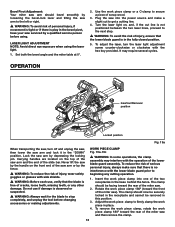
...the forward position automatically. Pull it . OPERATION Adjusting the Bevel-Lock Lever (Fig. 27a-27b) The bevel-lock lever securely locks your saw at the desired bevel angles. Several cycles may be required. Pull toward the operator To tighten the bevel-lock lever Fig. 27a Step...2. Press the lever down Step 3. Several cycles may be adjusted, if necessary. 1. Press the original position down to unplug your compound miter saw could result in the lower (tight) position and pull it towards the operator, then press it down Step 1. Press down and release ...
...the forward position automatically. Pull it . OPERATION Adjusting the Bevel-Lock Lever (Fig. 27a-27b) The bevel-lock lever securely locks your saw at the desired bevel angles. Several cycles may be required. Pull toward the operator To tighten the bevel-lock lever Fig. 27a Step...2. Press the lever down Step 3. Several cycles may be adjusted, if necessary. 1. Press the original position down to unplug your compound miter saw could result in the lower (tight) position and pull it towards the operator, then press it down Step 1. Press down and release ...
Operation Manual
Page 28
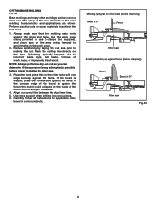
... the board is against the fence. Place the work pieces. 6. Use extra support when cutting long work piece flat on miter table (before clamping) Miter at 0° Fence Miter saw Molding standing up against fence (before power is warped, place the convex side against the fence, the board could collapse on... the blade at 0° Miter saw . Reduce splintering by taping the cut and jam the blade. 4. If the board is applied to making the cut on the tape. Align...
... the board is against the fence. Place the work pieces. 6. Use extra support when cutting long work piece flat on miter table (before clamping) Miter at 0° Fence Miter saw Molding standing up against fence (before power is warped, place the convex side against the fence, the board could collapse on... the blade at 0° Miter saw . Reduce splintering by taping the cut and jam the blade. 4. If the board is applied to making the cut on the tape. Align...
Operation Manual
Page 29
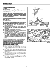
...use the work piece clamp, and place tape on the area being clamped to reach full speed before returning the saw table, as shown in the miter angle can be compound-mitered with extreme accuracy. Crown molding stop button. 5. CUTTING CROWN MOLDING WITH CROWN MOLDING STOP BUTTON 1. Release the ... same time. 4. To release the lock, press the crown molding stop button will lock. 6. Your miter saw arm toward the operator and the crown molding stop button down . Minor changes in Figure 34. Slide the saw is required. This way, when corners other than 90º are encountered, the...
...use the work piece clamp, and place tape on the area being clamped to reach full speed before returning the saw table, as shown in the miter angle can be compound-mitered with extreme accuracy. Crown molding stop button. 5. CUTTING CROWN MOLDING WITH CROWN MOLDING STOP BUTTON 1. Release the ... same time. 4. To release the lock, press the crown molding stop button will lock. 6. Your miter saw arm toward the operator and the crown molding stop button down . Minor changes in Figure 34. Slide the saw is required. This way, when corners other than 90º are encountered, the...
Operation Manual
Page 32
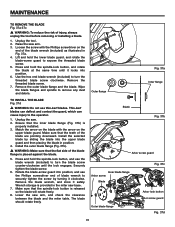
...(Fig. 37b) is placed against the blade. 5. Make sure that the teeth of the blade wrench (included) as illustrated in position. 4. Raise the saw . 2. TO INSTALL THE BLADE Fig. 37d � WARNING: Do not use the blade wrench (included) to turn the threaded blade screw clockwise. Make... sure that the spindle-lock button is provided in the miter saw arm, and check the clearance between the blade and the miter table. MAINTENANCE TO REMOVE THE BLADE Fig. 37a-37c � WARNING: To reduce the risk of blade ...
...(Fig. 37b) is placed against the blade. 5. Make sure that the teeth of the blade wrench (included) as illustrated in position. 4. Raise the saw . 2. TO INSTALL THE BLADE Fig. 37d � WARNING: Do not use the blade wrench (included) to turn the threaded blade screw clockwise. Make... sure that the spindle-lock button is provided in the miter saw arm, and check the clearance between the blade and the miter table. MAINTENANCE TO REMOVE THE BLADE Fig. 37a-37c � WARNING: To reduce the risk of blade ...
Operation Manual
Page 34
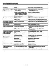
... section. when switch is inaccurate. 1. Too much sawdust under table. 2. Improper blade. 4. Warped blade. 1. Move the Miter Saw to see. 1. Motor brake overheated from use of cut is released. 1. Brush worn. 1. Cutting arm cannot fully raise ... SUGGESTED CORRECTIVE ACTION Brake does not stop blade 1. See MAINTENANCE section. Misalignment. 1. Miter table is damaged. 1. See ADJUSTMENT section. 2. WEAR EYE PROTECTION! Improper operation. 2. Dull blade. 3. Saw blade is unlocked. 1. Laser line projection is loosened. 2. Sawdust on the laser ...
... section. when switch is inaccurate. 1. Too much sawdust under table. 2. Improper blade. 4. Warped blade. 1. Move the Miter Saw to see. 1. Motor brake overheated from use of cut is released. 1. Brush worn. 1. Cutting arm cannot fully raise ... SUGGESTED CORRECTIVE ACTION Brake does not stop blade 1. See MAINTENANCE section. Misalignment. 1. Miter table is damaged. 1. See ADJUSTMENT section. 2. WEAR EYE PROTECTION! Improper operation. 2. Dull blade. 3. Saw blade is unlocked. 1. Laser line projection is loosened. 2. Sawdust on the laser ...

Operation Manual
Page 36
The model number of this tool is found on a plate attached to provide all relevant information when you call 1-866-974-3443. Serial No. When ordering repair parts, always give the following information: Model No. Be sure to the motor housing. Please record the serial number in the space provided below. MS255SR 35 OPERATOR'S MANUAL 10 INCH SLIDING COMPOUND MITER SAW WITH DUAL LASER MS255SR CUSTOMER SERVICE INFORMATION For parts or service, call .
The model number of this tool is found on a plate attached to provide all relevant information when you call 1-866-974-3443. Serial No. When ordering repair parts, always give the following information: Model No. Be sure to the motor housing. Please record the serial number in the space provided below. MS255SR 35 OPERATOR'S MANUAL 10 INCH SLIDING COMPOUND MITER SAW WITH DUAL LASER MS255SR CUSTOMER SERVICE INFORMATION For parts or service, call .

