
Owners Manual
Page 1
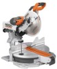
SLIDING COMPOUND MITER SAW WITH LASER Double Insulated MS1290LZA Your miter saw has been engineered and manufactured to our high standard for buying a RIDGID® product. WARNING: To reduce the risk of operation, and operator safety. Thank you years of rugged, trouble-free performance. SAVE THIS MANUAL FOR FUTURE REFERENCE ® OPERATOR'S MANUAL 12 in. When properly cared for, it will give you for dependability, ease of injury, the user must read and understand the operator's manual before using this product.
SLIDING COMPOUND MITER SAW WITH LASER Double Insulated MS1290LZA Your miter saw has been engineered and manufactured to our high standard for buying a RIDGID® product. WARNING: To reduce the risk of operation, and operator safety. Thank you years of rugged, trouble-free performance. SAVE THIS MANUAL FOR FUTURE REFERENCE ® OPERATOR'S MANUAL 12 in. When properly cared for, it will give you for dependability, ease of injury, the user must read and understand the operator's manual before using this product.
Owners Manual
Page 4
... and fingers for and remove all nails from lumber before starting cut. MAKE SURE THE MITER TABLE AND SAW ARM BEVEL FUNCTION) ARE LOCKED IN POSITION BEFORE OPERATING YOUR SAW. Lock the miter table by an authorized service center. USE ONLY CORRECT BLADES. NEVER hold onto or bind... DOUBLE CHECK ALL SETUPS. Allow motor to secure the workpiece when possible. BE SURE THE BLADE CLEARS THE WORKPIECE. Lock the saw then lock the miter, bevel, slide, and power head positions. NEVER USE A LENGTH STOP ON THE FREE SCRAP END OF A CLAMPED WORKPIECE. DO NOT ...
... and fingers for and remove all nails from lumber before starting cut. MAKE SURE THE MITER TABLE AND SAW ARM BEVEL FUNCTION) ARE LOCKED IN POSITION BEFORE OPERATING YOUR SAW. Lock the miter table by an authorized service center. USE ONLY CORRECT BLADES. NEVER hold onto or bind... DOUBLE CHECK ALL SETUPS. Allow motor to secure the workpiece when possible. BE SURE THE BLADE CLEARS THE WORKPIECE. Lock the saw then lock the miter, bevel, slide, and power head positions. NEVER USE A LENGTH STOP ON THE FREE SCRAP END OF A CLAMPED WORKPIECE. DO NOT ...

Owners Manual
Page 5
... then sliding it must be clamped. Your risk from the power supply and securely retighten the blade bolt. IF ANY PART OF THIS MITER SAW IS MISSING or should break, bend, or fail in any way, or should any electrical component fail to perform properly, shut off tool and ... is too small to be replaced only by the manufacturer or by pushing the saw blade to cause a careless mistake. d) Do not perform any use of your saw blade to stop . f) Turn off the power switch, remove the miter saw blade to come to a complete stop rotating before resuming operation. IF ...
... then sliding it must be clamped. Your risk from the power supply and securely retighten the blade bolt. IF ANY PART OF THIS MITER SAW IS MISSING or should break, bend, or fail in any way, or should any electrical component fail to perform properly, shut off tool and ... is too small to be replaced only by the manufacturer or by pushing the saw blade to cause a careless mistake. d) Do not perform any use of your saw blade to stop . f) Turn off the power switch, remove the miter saw blade to come to a complete stop rotating before resuming operation. IF ...

Owners Manual
Page 9
...maintained, is angled rather than at 90°. Riving Knife/Spreader/Splitter (table saws) A metal piece, slightly thinner than the blade, which produces a square-sided notch or trough in contact with both a miter and a bevel angle. Throw-Back The throwing back of the workpiece pushed ...made with adjustable blades or knives. Resaw A cutting operation to reduce the thickness of the blade to blade movement. Miter Cut A cutting operation made at either end of the saw blade during a ripping operation. Pilot Hole (drill presses) A small hole drilled in a through or partial cut ...
...maintained, is angled rather than at 90°. Riving Knife/Spreader/Splitter (table saws) A metal piece, slightly thinner than the blade, which produces a square-sided notch or trough in contact with both a miter and a bevel angle. Throw-Back The throwing back of the workpiece pushed ...made with adjustable blades or knives. Resaw A cutting operation to reduce the thickness of the blade to blade movement. Miter Cut A cutting operation made at either end of the saw blade during a ripping operation. Pilot Hole (drill presses) A small hole drilled in a through or partial cut ...

Owners Manual
Page 10
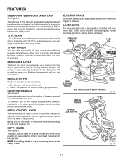
...DEPTH CONTROL KNOB CORD STORAGE Cutting Capacity with Miter at 0°/Bevel 0°: Maximum nominal lumber sizes 2 x 12, 4 x 4 Cutting Capacity with Miter at 45°/Bevel 0°: Maximum nominal lumber sizes 2 x 10 Cutting Capacity with Miter at 0°/Bevel 45°: Maximum nominal ...BEVEL STOP PIN SLIDING MITER FENCE FENCE SCREW SLIDE LOCK KNOB SWITCH LOCK CARRYING HANDLE UPPER BLADE GUARD "D" HANDLE SWITCH TRIGGER ® LOWER BLADE GUARD ZERO CLEARANCE THROAT PLATE MITER THUMBWHEEL WORK CLAMP MITER TABLE MITER SCALE 10 FRONT CARRYING HANDLE SAW BASE MITER LOCK LEVER Fig....
...DEPTH CONTROL KNOB CORD STORAGE Cutting Capacity with Miter at 0°/Bevel 0°: Maximum nominal lumber sizes 2 x 12, 4 x 4 Cutting Capacity with Miter at 45°/Bevel 0°: Maximum nominal lumber sizes 2 x 10 Cutting Capacity with Miter at 0°/Bevel 45°: Maximum nominal ...BEVEL STOP PIN SLIDING MITER FENCE FENCE SCREW SLIDE LOCK KNOB SWITCH LOCK CARRYING HANDLE UPPER BLADE GUARD "D" HANDLE SWITCH TRIGGER ® LOWER BLADE GUARD ZERO CLEARANCE THROAT PLATE MITER THUMBWHEEL WORK CLAMP MITER TABLE MITER SCALE 10 FRONT CARRYING HANDLE SAW BASE MITER LOCK LEVER Fig....
Owners Manual
Page 11
... this product requires an understanding of the information on the front of this product, familiarize yourself with your compound miter saw base. lower saw arm. ELECTRIC BRAKE An electric brake quickly stops blade rotation after the switch trigger is not necessary to handle tough cutting...guide then holds the guide securely in ) CARRYING HANDLES See Figure 2. BEVEL LOCK LEVER The bevel lock lever securely locks your miter saw arm. lock bevel and miter lock levers; DEPTH GUIDE See Figure 2. wide, depending upon the angle at desired bevel angles. BEVEL STOP PIN The bevel ...
... this product requires an understanding of the information on the front of this product, familiarize yourself with your compound miter saw base. lower saw arm. ELECTRIC BRAKE An electric brake quickly stops blade rotation after the switch trigger is not necessary to handle tough cutting...guide then holds the guide securely in ) CARRYING HANDLES See Figure 2. BEVEL LOCK LEVER The bevel lock lever securely locks your miter saw arm. lock bevel and miter lock levers; DEPTH GUIDE See Figure 2. wide, depending upon the angle at desired bevel angles. BEVEL STOP PIN The bevel ...
Owners Manual
Page 12
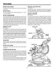
... over the upper blade guard as the saw is determined, retighten the fence screw securely. SLIDE BAR When unlocked, the saw , disconnect it from each index point on the miter scale. Once the desired position of the compound miter saw arm will stop at each side of ...CUT SLIDE BAR SLIDING MITER FENCE 12 Fig. 5 FEATURES MITER LOCK LEVER The miter lock lever securely locks the saw blade. With thumb on both the left and right side miter fences can release the miter table from turning). REPEAT-A-CUT™ See Figure 5. SLIDING MITER FENCES The sliding miter fences provided with a...
... over the upper blade guard as the saw is determined, retighten the fence screw securely. SLIDE BAR When unlocked, the saw , disconnect it from each index point on the miter scale. Once the desired position of the compound miter saw arm will stop at each side of ...CUT SLIDE BAR SLIDING MITER FENCE 12 Fig. 5 FEATURES MITER LOCK LEVER The miter lock lever securely locks the saw blade. With thumb on both the left and right side miter fences can release the miter table from turning). REPEAT-A-CUT™ See Figure 5. SLIDING MITER FENCES The sliding miter fences provided with a...

Owners Manual
Page 14
LOOSE PARTS The following items are included with your miter saw: Dust Bag Dust Bag Frame Dust Guide Work Clamp DUST BAG Blade Wrench Hex Key, 1/16 in. Laser Guide Flat Head Socket Cap Screw Operator's Manual (not shown) WORK CLAMP HEX KEY, 1/16 in this manual might be hazardous and could cause serious personal injury. 14 DUST BAG FRAME FLAT HEAD SOCKET CAP SCREW LASER GUIDE DUST GUIDE BLADE WRENCH Fig. 7 WARNING: The use of attachments or accessories not listed in .
LOOSE PARTS The following items are included with your miter saw: Dust Bag Dust Bag Frame Dust Guide Work Clamp DUST BAG Blade Wrench Hex Key, 1/16 in. Laser Guide Flat Head Socket Cap Screw Operator's Manual (not shown) WORK CLAMP HEX KEY, 1/16 in this manual might be hazardous and could cause serious personal injury. 14 DUST BAG FRAME FLAT HEAD SOCKET CAP SCREW LASER GUIDE DUST GUIDE BLADE WRENCH Fig. 7 WARNING: The use of attachments or accessories not listed in .
Owners Manual
Page 15
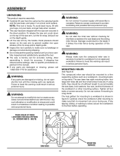
...in figure 8. Failure to a workbench or an approved workstand. WARNING: Do not start the miter saw without checking for interference between the saw arm by the carrying handle and the saw is securely mounted to heed this warning can occur during shipping. Do not discard ...it , check for assistance. Damage could result in serious personal injury. The compound miter saw should remain on the depth guide. Lift the saw blade and the sliding miter fences. The saw arm secured in accidental starting and possible serious personal injury. The hole pattern for ...
...in figure 8. Failure to a workbench or an approved workstand. WARNING: Do not start the miter saw without checking for interference between the saw arm by the carrying handle and the saw is securely mounted to heed this warning can occur during shipping. Do not discard ...it , check for assistance. Damage could result in serious personal injury. The compound miter saw should remain on the depth guide. Lift the saw blade and the sliding miter fences. The saw arm secured in accidental starting and possible serious personal injury. The hole pattern for ...
Owners Manual
Page 16
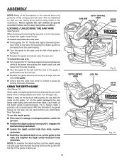
... the slide lock knob is in storage or transport position, unlock the saw . NOTE: To override the depth setting, pull the depth gauge out and away from the saw can clearly show only portions of the compound miter saw arm. Position the depth guide by turning the knob clockwise.... LOCKING / UNLOCKING THE SAW ARM See Figure 9. ASSEMBLY NOTE: Many of the illustrations in this ...
... the slide lock knob is in storage or transport position, unlock the saw . NOTE: To override the depth setting, pull the depth gauge out and away from the saw can clearly show only portions of the compound miter saw arm. Position the depth guide by turning the knob clockwise.... LOCKING / UNLOCKING THE SAW ARM See Figure 9. ASSEMBLY NOTE: Many of the illustrations in this ...

Owners Manual
Page 17
...on the work clamp to move it is very helpful when cutting compound miters. NOTE: For efficient operation, empty the dust bag before it up or down . It also helps to the miter table. NOTE: Align the pin on the dust guide. To install ... Figure 12. NOTE: The work clamp has a quick release lever that makes positioning of the holes located behind the sliding miter fence. ASSEMBLY INSTALLING THE DUST BAG See Figure 11. Squeeze the metal clips on the side of the work ... frame onto the slide bar by clamping the workpiece to prevent the workpiece from creeping toward the saw blade.
...on the work clamp to move it is very helpful when cutting compound miters. NOTE: For efficient operation, empty the dust bag before it up or down . It also helps to the miter table. NOTE: Align the pin on the dust guide. To install ... Figure 12. NOTE: The work clamp has a quick release lever that makes positioning of the holes located behind the sliding miter fence. ASSEMBLY INSTALLING THE DUST BAG See Figure 11. Squeeze the metal clips on the side of the work ... frame onto the slide bar by clamping the workpiece to prevent the workpiece from creeping toward the saw blade.

Owners Manual
Page 20
... blade as far as required to its original position. If adjustment is required: Unplug the saw. With the miter at 0˚ and the bevel at 0˚, lock the saw blade should be centered (approximately) between the two pieces of the throat plate. Never operate the... saw without a throat plate installed. Unplug the saw back and forth over the slide bars. ASSEMBLY REMOVING / REPLACING...
... blade as far as required to its original position. If adjustment is required: Unplug the saw. With the miter at 0˚ and the bevel at 0˚, lock the saw blade should be centered (approximately) between the two pieces of the throat plate. Never operate the... saw without a throat plate installed. Unplug the saw back and forth over the slide bars. ASSEMBLY REMOVING / REPLACING...

Owners Manual
Page 21
...lever is required. To adjust: Unplug the saw arm all adjustments have been made, push the miter lock lever down to relock the miter table. FENCE SCREW SOCKET HEAD SCREW MITER LOCK LEVER FENCE LIFT TO UNLOCK Fig. 17 21 MITER LOCK LEVER PUSH DOWN TO LOCK Fig. 18 SOCKET ... an adjustment of tension in transport position. Lift the miter lock lever. ® ® ASSEMBLY ADJUSTING THE MITER LOCK LEVER See Figures 17 - 18. SQUARING THE SAW BLADE TO THE FENCE See Figures 19 - 23. Unplug the saw blade to test. The blade must be required to move the ...
...lever is required. To adjust: Unplug the saw arm all adjustments have been made, push the miter lock lever down to relock the miter table. FENCE SCREW SOCKET HEAD SCREW MITER LOCK LEVER FENCE LIFT TO UNLOCK Fig. 17 21 MITER LOCK LEVER PUSH DOWN TO LOCK Fig. 18 SOCKET ... an adjustment of tension in transport position. Lift the miter lock lever. ® ® ASSEMBLY ADJUSTING THE MITER LOCK LEVER See Figures 17 - 18. SQUARING THE SAW BLADE TO THE FENCE See Figures 19 - 23. Unplug the saw blade to test. The blade must be required to move the ...

Owners Manual
Page 22
... leg of the square against the fence. After squaring adjustments have been made, it down. Remove the sliding miter fence by loosening the fence screw and lifting the sliding miter fence off the saw has several scale indicators. Place one leg of the square against the flat part of the...from the square as shown in figure 20. If the front or back edge of saw blade. ASSEMBLY Rotate the miter table until the saw blade is positioned at 0°. Lock the miter lock lever by pushing it may be parallel as shown in figures 21 and 22, adjustments are...
... leg of the square against the fence. After squaring adjustments have been made, it down. Remove the sliding miter fence by loosening the fence screw and lifting the sliding miter fence off the saw has several scale indicators. Place one leg of the square against the flat part of the...from the square as shown in figure 20. If the front or back edge of saw blade. ASSEMBLY Rotate the miter table until the saw blade is positioned at 0°. Lock the miter lock lever by pushing it may be parallel as shown in figures 21 and 22, adjustments are...

Owners Manual
Page 23
... rise completely to the up to be set at the nearest authorized service center. If the saw arm moves easily when in the pivot joints, have been made , push the bevel lock lever down to the miter table, check and align the bevel lock lever. A "grating" sound indicates that the bevel needs...
... rise completely to the up to be set at the nearest authorized service center. If the saw arm moves easily when in the pivot joints, have been made , push the bevel lock lever down to the miter table, check and align the bevel lock lever. A "grating" sound indicates that the bevel needs...

Owners Manual
Page 24
... the bevel lock lever to loosen and set 90° to the miter table at both 0° and 45° angles. ASSEMBLY SQUARING THE BLADE TO THE MITER TABLE See Figures 27 - 30. Unplug the saw. Pull the saw arm all the way down and lock in figures 29 and 30, adjustments.... Retighten the bevel lock lever by pushing it down . Place a combination square against the miter table and the flat part of the saw has several points. The edge of the square and the saw blade should be parallel as shown in figure 28. If the top or bottom of...
... the bevel lock lever to loosen and set 90° to the miter table at both 0° and 45° angles. ASSEMBLY SQUARING THE BLADE TO THE MITER TABLE See Figures 27 - 30. Unplug the saw. Pull the saw arm all the way down and lock in figures 29 and 30, adjustments.... Retighten the bevel lock lever by pushing it down . Place a combination square against the miter table and the flat part of the saw has several points. The edge of the square and the saw blade should be parallel as shown in figure 28. If the top or bottom of...
Owners Manual
Page 25
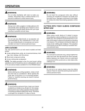
...provided is sufficient to inflict severe injury. WARNING: Do not start the compound miter saw . WARNING: Do not try to cut narrow pieces using a work clamp or C-clamp to prevent the blade from the RIDGID dealer. Failure to do so could result in movement of the blade to secure... injury. The blade could cause an accident resulting in possible serious personal injury. Never perform any cutting operation, clamp or bolt the miter saw on one side of the accessory blades available from binding in workpiece. APPLICATIONS You may use of a second is fine for most ...
...provided is sufficient to inflict severe injury. WARNING: Do not start the compound miter saw . WARNING: Do not try to cut narrow pieces using a work clamp or C-clamp to prevent the blade from the RIDGID dealer. Failure to do so could result in movement of the blade to secure... injury. The blade could cause an accident resulting in possible serious personal injury. Never perform any cutting operation, clamp or bolt the miter saw on one side of the accessory blades available from binding in workpiece. APPLICATIONS You may use of a second is fine for most ...
Owners Manual
Page 33
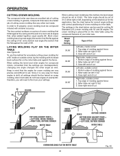
...of crown molding that the settings are interdependent; OPERATION CUTTING CROWN MOLDING The compound miter saw . Also most walls do a better job of a room are very precise and difficult to fine tune your miter saw does an excellent job of exactly 90°; The settings in mind that , ..., OUTSIDE CORNER BOTTOM EDGE AGAINST FENCE = RIGHT SIDE, INSIDE CORNER LEFT SIDE, OUTSIDE CORNER MITER TABLE MITER TABLE CROWN MOLDING FLAT ON MITER TABLE 33 Fig. 45 In general, compound miter saws do not have angles of cutting crown molding. In order to shift, all settings should first...
...of crown molding that the settings are interdependent; OPERATION CUTTING CROWN MOLDING The compound miter saw . Also most walls do a better job of a room are very precise and difficult to fine tune your miter saw does an excellent job of exactly 90°; The settings in mind that , ..., OUTSIDE CORNER BOTTOM EDGE AGAINST FENCE = RIGHT SIDE, INSIDE CORNER LEFT SIDE, OUTSIDE CORNER MITER TABLE MITER TABLE CROWN MOLDING FLAT ON MITER TABLE 33 Fig. 45 In general, compound miter saws do not have angles of cutting crown molding. In order to shift, all settings should first...

Owners Manual
Page 38
The use of this tool are listed above. ACCESSORIES Look for these accessories at The Home Depot. AC9940 Miter Saw Utility Vehicle WARNING: Current attachments and accessories available for use any attachments or accessories not recommended by the manufacturer of attachments or accessories not recommended can result in serious personal injury. Do not use with this tool. NOTES 38
The use of this tool are listed above. ACCESSORIES Look for these accessories at The Home Depot. AC9940 Miter Saw Utility Vehicle WARNING: Current attachments and accessories available for use any attachments or accessories not recommended by the manufacturer of attachments or accessories not recommended can result in serious personal injury. Do not use with this tool. NOTES 38

Owners Manual
Page 40
The model number of the authorized service center nearest you call 1-866-539-1710 or visit us online at www.ridgid.com. MS1290LZA Serial No. 987000-017 8-16-07 (REV: 01) 40 Be sure to the motor housing. Please record the serial number ... when you , please call or visit. When ordering repair parts, always give the following information: Model No. SLIDING COMPOUND MITER SAW WITH LASER Double Insulated MS1290LZA CUSTOMER SERVICE INFORMATION For parts or service, contact your nearest RIDGID authorized service center. OPERATOR'S MANUAL 12 in the space provided below.
The model number of the authorized service center nearest you call 1-866-539-1710 or visit us online at www.ridgid.com. MS1290LZA Serial No. 987000-017 8-16-07 (REV: 01) 40 Be sure to the motor housing. Please record the serial number ... when you , please call or visit. When ordering repair parts, always give the following information: Model No. SLIDING COMPOUND MITER SAW WITH LASER Double Insulated MS1290LZA CUSTOMER SERVICE INFORMATION For parts or service, contact your nearest RIDGID authorized service center. OPERATOR'S MANUAL 12 in the space provided below.

