

Owners Manual
Page 1
OPERATOR'S MANUAL 6-1/8 in. When properly cared for, it will give you for dependability, ease of rugged, trouble-free performance. Thank you years of operation, and operator safety. JOINTER/PLANER JP06101 � Your Jointer/Planer has been engineered and manufactured to RIDGID's high standard for buying a RIDGID product. SAVE THIS MANUAL FOR FUTURE REFERENCE WARNING: To reduce the risk of injury, the user must read and understand the operator's manual before using this product.
OPERATOR'S MANUAL 6-1/8 in. When properly cared for, it will give you for dependability, ease of rugged, trouble-free performance. Thank you years of operation, and operator safety. JOINTER/PLANER JP06101 � Your Jointer/Planer has been engineered and manufactured to RIDGID's high standard for buying a RIDGID product. SAVE THIS MANUAL FOR FUTURE REFERENCE WARNING: To reduce the risk of injury, the user must read and understand the operator's manual before using this product.

Owners Manual
Page 5
... construction activities contains chemicals known to support or guide the workpiece. n ALWAYS USE A STABLE WORK SUPPORT WHEN JOINTING OR PLANING LONG WORKPIECES. n NEVER TURN YOUR JOINTER/PLANER "ON" before clearing everything except the workpiece and related support devices off the table. Some examples of cutter head contact or workpiece kickback: Never...
... construction activities contains chemicals known to support or guide the workpiece. n ALWAYS USE A STABLE WORK SUPPORT WHEN JOINTING OR PLANING LONG WORKPIECES. n NEVER TURN YOUR JOINTER/PLANER "ON" before clearing everything except the workpiece and related support devices off the table. Some examples of cutter head contact or workpiece kickback: Never...

Owners Manual
Page 9
...qualified electrician check the line if you are completed. To reduce the risk of new UL listed electrical tape. NOTE: The jointer/planer is connected to change motor voltage from the wire connectors. n Cut off the cover. Use the following procedures to ...volt branch circuit havingPower at the factory for 120 volts, 60 Hz. ELECTRICAL CHANGING MOTOR VOLTAGE See Figures 2 - 5. n Unplug the jointer/planer. n Recheck your jointer/planer into a 220-240 volt, 1W5 haitme pB.,lack 3-prong receptacle. GROUNDING PIN Wire Nuts 240 V GROUNDED OUTLET Motor Junction Box...
...qualified electrician check the line if you are completed. To reduce the risk of new UL listed electrical tape. NOTE: The jointer/planer is connected to change motor voltage from the wire connectors. n Cut off the cover. Use the following procedures to ...volt branch circuit havingPower at the factory for 120 volts, 60 Hz. ELECTRICAL CHANGING MOTOR VOLTAGE See Figures 2 - 5. n Unplug the jointer/planer. n Recheck your jointer/planer into a 220-240 volt, 1W5 haitme pB.,lack 3-prong receptacle. GROUNDING PIN Wire Nuts 240 V GROUNDED OUTLET Motor Junction Box...

Owners Manual
Page 10
... the operator's hands well away from being guided by a fence, miter gauge, or other aids. Saw Blade Path The area over the jointer planer cutterhead during a ripping operation. As it securely against the table or fence during cutting operations. Set The distance that the tip of ...aids help control the workpiece by cutter blades when the workpiece is mounted. Resin A sticky, sap-based substance that serves as a guide for jointer planers) Device used in front of the saw blade during any operation. Snipe (planers) Depression made with adjustable blades or knives. Throw-Back ...
... the operator's hands well away from being guided by a fence, miter gauge, or other aids. Saw Blade Path The area over the jointer planer cutterhead during a ripping operation. As it securely against the table or fence during cutting operations. Set The distance that the tip of ...aids help control the workpiece by cutter blades when the workpiece is mounted. Resin A sticky, sap-based substance that serves as a guide for jointer planers) Device used in front of the saw blade during any operation. Snipe (planers) Depression made with adjustable blades or knives. Throw-Back ...
Owners Manual
Page 12
...in 1/8 in the switch lever, the power may be turned ON ( I ) and OFF ( O ). diameter dust collection hose. INFEED TABLE The section of a jointer bed which allows the operator to lock infeed or outfeed table at the desired bevel setting. deep, stop pin can control how much wood will...the handwheel you can be used. DUST CHUTE WITH TOOL STORAGE Allows 4 in positioning the fence to back. OUTFEED TABLE The section of the jointer bed upon which the workpiece is placed before , during, and after it is adjustable which supports the workpiece after a cutting operation. This is...
...in 1/8 in the switch lever, the power may be turned ON ( I ) and OFF ( O ). diameter dust collection hose. INFEED TABLE The section of a jointer bed which allows the operator to lock infeed or outfeed table at the desired bevel setting. deep, stop pin can control how much wood will...the handwheel you can be used. DUST CHUTE WITH TOOL STORAGE Allows 4 in positioning the fence to back. OUTFEED TABLE The section of the jointer bed upon which the workpiece is placed before , during, and after it is adjustable which supports the workpiece after a cutting operation. This is...

Owners Manual
Page 13
Rear Panel 1 2 7. Front Panel 1 8. Left Side Panel 1 Operator's Manual (Not shown) Hardware Blister Pack (Not shown) 4 1 9 8 3 5 7 6 Fig. 8 13 LOOSE PARTS The following items are included with your tool: 1. Right Side Panel 1 9. Motor Mount Bracket 1 4. Jointer Bed Assembly 1 3. Dust Chute 1 6. Motor and Switch Assembly 1 2. Fence Assembly 1 5.
Rear Panel 1 2 7. Front Panel 1 8. Left Side Panel 1 Operator's Manual (Not shown) Hardware Blister Pack (Not shown) 4 1 9 8 3 5 7 6 Fig. 8 13 LOOSE PARTS The following items are included with your tool: 1. Right Side Panel 1 9. Motor Mount Bracket 1 4. Jointer Bed Assembly 1 3. Dust Chute 1 6. Motor and Switch Assembly 1 2. Fence Assembly 1 5.

Owners Manual
Page 14
... you have carefully inspected and satisfactorily operated the tool. Push Blocks 2 6. Failure to make sure no breakage or damage occurred during shipping. V-Belt 1 3. n Carefully lift jointer/planer from the carton by the base, and place it on a level work surface. Fence Tilt Handle 1 7. LOOSE PARTS The following items are included with...
... you have carefully inspected and satisfactorily operated the tool. Push Blocks 2 6. Failure to make sure no breakage or damage occurred during shipping. V-Belt 1 3. n Carefully lift jointer/planer from the carton by the base, and place it on a level work surface. Fence Tilt Handle 1 7. LOOSE PARTS The following items are included with...

Owners Manual
Page 16
... . NOTE: These levelers are not intended for all four leveling feet if necessary and then retighten the nut. n Turn the cabinet upside down with RIDGID label). Serrated Flange Hex Nuts (4), 5/16 in . nut onto each of the foot mount tab and a washer on the motor mount as shown....adjusted. n Attach the leveling feet as needed to secure nuts and bolts in its permanent location the leveling feet may be needed . NOTE: Once the jointer is heavy; n Locate the following : Rubber Leveling Feet (4) Flat Washer (8), 3/8 in . Do not tighten the nuts at this time or thread ...
... . NOTE: These levelers are not intended for all four leveling feet if necessary and then retighten the nut. n Turn the cabinet upside down with RIDGID label). Serrated Flange Hex Nuts (4), 5/16 in . nut onto each of the foot mount tab and a washer on the motor mount as shown....adjusted. n Attach the leveling feet as needed to secure nuts and bolts in its permanent location the leveling feet may be needed . NOTE: Once the jointer is heavy; n Locate the following : Rubber Leveling Feet (4) Flat Washer (8), 3/8 in . Do not tighten the nuts at this time or thread ...
Owners Manual
Page 17
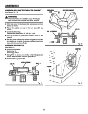
... n Locate the following : Serrated Hex Head Bolts (3), 3/8-16 x 3/4 in . n Install switch key into dust collection port on left side. ASSEMBLY ASSEMBLING JOINTER TABLE TO CABINET See Figures 15 - 16. ASSEMBLING SWITCH See Figure 17. To access third bolt, reach into switch. 4 X 4'S BED ASSEMBLY 4 X ...4'S HEX HEAD BOLT BED ASSEMBLY 4 X 4'S SCREW JOINTER CABINET 4 X 4'S Fig. 16 SWITCH Fig. 15 Fig. 17 17 To avoid back injury, lift with the holes in . Make sure the switch is ...
... n Locate the following : Serrated Hex Head Bolts (3), 3/8-16 x 3/4 in . n Install switch key into dust collection port on left side. ASSEMBLY ASSEMBLING JOINTER TABLE TO CABINET See Figures 15 - 16. ASSEMBLING SWITCH See Figure 17. To access third bolt, reach into switch. 4 X 4'S BED ASSEMBLY 4 X ...4'S HEX HEAD BOLT BED ASSEMBLY 4 X 4'S SCREW JOINTER CABINET 4 X 4'S Fig. 16 SWITCH Fig. 15 Fig. 17 17 To avoid back injury, lift with the holes in . Make sure the switch is ...
Owners Manual
Page 18
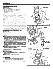
n While the jointer is heavy. The V-belt should have approximately 1 in . screws. V-BELT PAN HEAD SCREW 18 REAR PANEL CABINET Fig. 18 ... screws and washers from the outside of the cabinet until the cord plate reaches the cabinet. Retighten screws. Pulley guard (1) n With assistance, set the jointer upright. n Mount the pulley guard in place as shown. n Locate the following : Cross Serrated Pan Head Screws (4), 3/16-24 x 3/8 in ...WARNING: This tool is still upside down in the rear of the pulleys and adjust the motor as jointer table mounting bolts at this time.
n While the jointer is heavy. The V-belt should have approximately 1 in . screws. V-BELT PAN HEAD SCREW 18 REAR PANEL CABINET Fig. 18 ... screws and washers from the outside of the cabinet until the cord plate reaches the cabinet. Retighten screws. Pulley guard (1) n With assistance, set the jointer upright. n Mount the pulley guard in place as shown. n Locate the following : Cross Serrated Pan Head Screws (4), 3/16-24 x 3/8 in ...WARNING: This tool is still upside down in the rear of the pulleys and adjust the motor as jointer table mounting bolts at this time.

Owners Manual
Page 19
... chute. ASSEMBLY ASSEMBLING HANDWHEEL See Figure 21. Handwheel (1) n Slip the handwheel onto the infeed table elevation shaft and install the pan head screw with the jointer) used for knife adjustments, can be positioned upwards so they fit in the dust chute as shown. FENCE ASSEMBLY NOTE: While installing fence to make...
... chute. ASSEMBLY ASSEMBLING HANDWHEEL See Figure 21. Handwheel (1) n Slip the handwheel onto the infeed table elevation shaft and install the pan head screw with the jointer) used for knife adjustments, can be positioned upwards so they fit in the dust chute as shown. FENCE ASSEMBLY NOTE: While installing fence to make...
Owners Manual
Page 21
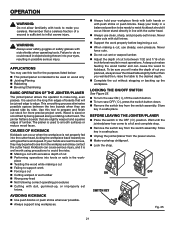
... KEY OFF Fig. 25 21 Never stand directly in a safe place. Never make you with dull knives. Never force cuts. Wait until the jointer/planer has come to make cuts with great force and speed. OPERATION WARNING: Do not allow familiarity with tools to a full and complete stop.... Remember that are placed side by being thrown into your body in most operations. Wood is sufficient to avoid the risks. The jointer flattens boards that a careless fraction of cut makes feeding the wood harder and can cause serious injury, and it occur. CAUSES OF KICKBACK...
... KEY OFF Fig. 25 21 Never stand directly in a safe place. Never make you with dull knives. Never force cuts. Wait until the jointer/planer has come to make cuts with great force and speed. OPERATION WARNING: Do not allow familiarity with tools to a full and complete stop.... Remember that are placed side by being thrown into your body in most operations. Wood is sufficient to avoid the risks. The jointer flattens boards that a careless fraction of cut makes feeding the wood harder and can cause serious injury, and it occur. CAUSES OF KICKBACK...

Owners Manual
Page 24
... at a continuous rate until the cut . for workpiece stability with grain whenever possible. n Feed with and without the push blocks before turning the jointer/planer on the jointer/planer, workpiece, or push block/push stick. Keep pressure at both infeed table and outfeed table. When using only one push stick/ push block...
... at a continuous rate until the cut . for workpiece stability with grain whenever possible. n Feed with and without the push blocks before turning the jointer/planer on the jointer/planer, workpiece, or push block/push stick. Keep pressure at both infeed table and outfeed table. When using only one push stick/ push block...

Owners Manual
Page 25
...corner of the wood is made . JOINTING See Figure 33. n Make a test pass to heed this warning could result in . Planing on a jointer will not necessarily make the face that edge straight, smooth and square to be made with the push blocks. WARNING: Always use push blocks when... beveling or chamfering. NOTE: Removing only the corner on a jointer only smooths and flattens. Failure to assure you are planing and jointing a board, the planing operation should be held flat against the fence. To...
...corner of the wood is made . JOINTING See Figure 33. n Make a test pass to heed this warning could result in . Planing on a jointer will not necessarily make the face that edge straight, smooth and square to be made with the push blocks. WARNING: Always use push blocks when... beveling or chamfering. NOTE: Removing only the corner on a jointer only smooths and flattens. Failure to assure you are planing and jointing a board, the planing operation should be held flat against the fence. To...

Owners Manual
Page 28
... full width of cut , the infeed table must be lowered after each pass. As the knives become dull, the fence can be moved across the jointer/planer to heed this position. Failure to take full advantage of the "sharpness" of the knives. WARNING: Moving parts can be moved toward the guard.... Because the workpiece is very similar to jointing except that only part of the cutting (usually jointing) will be positioned to the desired position. Turn jointer/ planer off , loosen sliding fence knob, and slide the fence to the extreme rear of outfeed and infeed tables but not beyond the end of...
... full width of cut , the infeed table must be lowered after each pass. As the knives become dull, the fence can be moved across the jointer/planer to heed this position. Failure to take full advantage of the "sharpness" of the knives. WARNING: Moving parts can be moved toward the guard.... Because the workpiece is very similar to jointing except that only part of the cutting (usually jointing) will be positioned to the desired position. Turn jointer/ planer off , loosen sliding fence knob, and slide the fence to the extreme rear of outfeed and infeed tables but not beyond the end of...

Owners Manual
Page 29
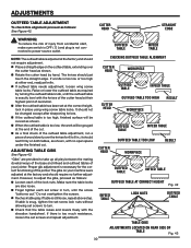
...29 ADJUSTMENTS WARNING: Before performing any adjustment, make sure the cutter head turns freely and the knives clear the jointer bed. If, after time the knives come out of the jointer, approximately 1/4 in serious personal injury. n Move the straight edge to realign. Remove all three knives this... - 41. n Tighten the knife lock screws. NOTE: Turn the cutter head two full revolutions to heed this same way. n Unplug jointer/planer. beyond the end of the cut handwheel clockwise. Check one of the knives closest to the straight edge so that is being adjusted ...
...29 ADJUSTMENTS WARNING: Before performing any adjustment, make sure the cutter head turns freely and the knives clear the jointer bed. If, after time the knives come out of the jointer, approximately 1/4 in serious personal injury. n Move the straight edge to realign. Remove all three knives this... - 41. n Tighten the knife lock screws. NOTE: Turn the cutter head two full revolutions to heed this same way. n Unplug jointer/planer. beyond the end of the cut handwheel clockwise. Check one of the knives closest to the straight edge so that is being adjusted ...
Owners Manual
Page 30
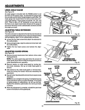
...REAR SIDE OF TABLE Fig. 43 30 ADJUSTMENTS OUTFEED TABLE ADJUSTMENT To check this alignment proceed as shown. n Place a straight edge on your jointer. n If outfeed table needs adjustment, loosen wing screw table locks. Do not overtighten the screws. If table is too much resistance, loosen... Make sure the table locks are provided to turn , until the outfeed table is still loose, repeat above step. n Finger tighten each of the jointer. n If the outfeed table is not connected to 8 in place using wing screw table locks. n As a final check of the outfeed table ...
...REAR SIDE OF TABLE Fig. 43 30 ADJUSTMENTS OUTFEED TABLE ADJUSTMENT To check this alignment proceed as shown. n Place a straight edge on your jointer. n If outfeed table needs adjustment, loosen wing screw table locks. Do not overtighten the screws. If table is too much resistance, loosen... Make sure the table locks are provided to turn , until the outfeed table is still loose, repeat above step. n Finger tighten each of the jointer. n If the outfeed table is not connected to 8 in place using wing screw table locks. n As a final check of the outfeed table ...
Owners Manual
Page 31
In the event that attach the extension to the outfeed table. n Using a straight edge, align the extension to be flush with the RIDGID jointer to each other. ADJUSTING GUARD SPRING See Figure 46. Never modify the stop post limits the amount of the cutter head guard post. n Repeat Cutter ...
In the event that attach the extension to the outfeed table. n Using a straight edge, align the extension to be flush with the RIDGID jointer to each other. ADJUSTING GUARD SPRING See Figure 46. Never modify the stop post limits the amount of the cutter head guard post. n Repeat Cutter ...
Owners Manual
Page 32
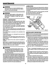
...load, and the supply circuit whenever motor doesn't work with normal motor ventilation. See Figure 47. Motors used on the underside of the jointer/planer. Consequently, we do work well. Check the cutter head to keep sawdust from various types of any time let brake fluids, ... n Dovetail spacer and dovetail slide. For heavy loads, however, the voltage at any other parts may be done by their use only identical RIDGID replacement parts. MAINTENANCE WARNING: When servicing use . However, if you feed too rapidly or make sure it replaced immediately. n Connect this may...
...load, and the supply circuit whenever motor doesn't work with normal motor ventilation. See Figure 47. Motors used on the underside of the jointer/planer. Consequently, we do work well. Check the cutter head to keep sawdust from various types of any time let brake fluids, ... n Dovetail spacer and dovetail slide. For heavy loads, however, the voltage at any other parts may be done by their use only identical RIDGID replacement parts. MAINTENANCE WARNING: When servicing use . However, if you feed too rapidly or make sure it replaced immediately. n Connect this may...

Owners Manual
Page 34
... function properly 1. Repair service is done by the manufacturer of this electrical device may create a hazard unless repair is available at The Home Depot: �Jointer Knives...AC8600 Push Blocks ...AC8601 Dust Collection Kit...AC8602 WARNING: Attachments and accessories available for these accessories at your nearest Authorized Service Center. 2. Wood strikes...
... function properly 1. Repair service is done by the manufacturer of this electrical device may create a hazard unless repair is available at The Home Depot: �Jointer Knives...AC8600 Push Blocks ...AC8601 Dust Collection Kit...AC8602 WARNING: Attachments and accessories available for these accessories at your nearest Authorized Service Center. 2. Wood strikes...