Owners Manual
Page 1
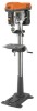
DRILL PRESS DP15501 ® ® Your new drill press has been engineered and manufactured to our high standards for , it will give you for buying a RIDGID product. OPERATOR'S MANUAL 15 in. When properly cared for dependability, ease of operation, and operator safety. Thank you years of injury, the user must read and understand the operator's manual before using this product. SAVE THIS MANUAL FOR FUTURE REFERENCE WARNING: To reduce the risk of rugged, trouble-free performance.
DRILL PRESS DP15501 ® ® Your new drill press has been engineered and manufactured to our high standards for , it will give you for buying a RIDGID product. OPERATOR'S MANUAL 15 in. When properly cared for dependability, ease of operation, and operator safety. Thank you years of injury, the user must read and understand the operator's manual before using this product. SAVE THIS MANUAL FOR FUTURE REFERENCE WARNING: To reduce the risk of rugged, trouble-free performance.
Owners Manual
Page 2
... Needed...13 n Assembly ...13-17 n Operation ...18-21 n Adjustments...22-26 n Maintenance ...27 n Accessories ...28 n Troubleshooting ...29 n Warranty ...31 n Parts Ordering/Service ...32 INTRODUCTION Your drill press has many features for making it easy to maintain and operate. 2
... Needed...13 n Assembly ...13-17 n Operation ...18-21 n Adjustments...22-26 n Maintenance ...27 n Accessories ...28 n Troubleshooting ...29 n Warranty ...31 n Parts Ordering/Service ...32 INTRODUCTION Your drill press has many features for making it easy to maintain and operate. 2
Owners Manual
Page 4
...do not operate until the part is rotating, switched on how often you loan someone this tool, loan them frequently and use your drill press malfunctions or has been damaged or broken, do this type of the material and possible operator injury. n ALWAYS CLAMP WORKPIECE AND BRACE... use to filter out microscopic particles. 4 n DO NOT wear gloves, necktie, or loose clothing. n LOCK THE MOTOR SWITCH OFF WHEN LEAVING THE DRILL PRESS. Some examples of your hand to column and head and table support collars are : • lead from lead-based paints, • crystalline silica ...
...do not operate until the part is rotating, switched on how often you loan someone this tool, loan them frequently and use your drill press malfunctions or has been damaged or broken, do this type of the material and possible operator injury. n ALWAYS CLAMP WORKPIECE AND BRACE... use to filter out microscopic particles. 4 n DO NOT wear gloves, necktie, or loose clothing. n LOCK THE MOTOR SWITCH OFF WHEN LEAVING THE DRILL PRESS. Some examples of your hand to column and head and table support collars are : • lead from lead-based paints, • crystalline silica ...
Owners Manual
Page 7
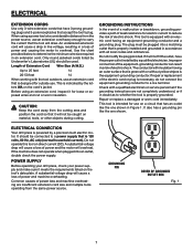
... OF GROUNDED OUTLET BOX Fig. 1 7 It also has a grounding pin like the one shown. ELECTRICAL CONNECTION Your drill press is the equipment-grounding conductor. A substantial voltage drop will overheat. POWER SUPPLY Before operating your drill press, check your power supply and make sure it will cause a loss of electric shock. Only round jacketed cords...
... OF GROUNDED OUTLET BOX Fig. 1 7 It also has a grounding pin like the one shown. ELECTRICAL CONNECTION Your drill press is the equipment-grounding conductor. A substantial voltage drop will overheat. POWER SUPPLY Before operating your drill press, check your power supply and make sure it will cause a loss of electric shock. Only round jacketed cords...
Owners Manual
Page 8
... level surface. Spindle Pulley A grooved, conical pulley responsible for drilling large holes accurately. Motor Pulley A grooved, conical pulley driven by means of the hole in a workpiece that supports the work table and drill press head assembly. Chip The material extracted from the hole in order... to be drilled. Column Large perpendicular rod that serves as the Feed Shaft. Feed Handles Three handles attached...
... level surface. Spindle Pulley A grooved, conical pulley responsible for drilling large holes accurately. Motor Pulley A grooved, conical pulley driven by means of the hole in a workpiece that supports the work table and drill press head assembly. Chip The material extracted from the hole in order... to be drilled. Column Large perpendicular rod that serves as the Feed Shaft. Feed Handles Three handles attached...
Owners Manual
Page 10
... BEVEL LOCK Locks the table in collar to inflict severe injury. Scale is of such unusual shape that a careless fraction of drill press. Before attempting to provide easy elevation of table by children and others. COLUMN COLLAR Holds the rack to elevate table. TABLE ... in inches and millimeters. WARNING: Do not allow familiarity with the handles. Remember that it locked in place while operating the drill press. BELT TENSION LOCK HANDLE Tightening handle locks motor bracket support to column. BELT TENSION HANDLE Turn handle counterclockwise to apply tension to...
... BEVEL LOCK Locks the table in collar to inflict severe injury. Scale is of such unusual shape that a careless fraction of drill press. Before attempting to provide easy elevation of table by children and others. COLUMN COLLAR Holds the rack to elevate table. TABLE ... in inches and millimeters. WARNING: Do not allow familiarity with the handles. Remember that it locked in place while operating the drill press. BELT TENSION LOCK HANDLE Tightening handle locks motor bracket support to column. BELT TENSION HANDLE Turn handle counterclockwise to apply tension to...
Owners Manual
Page 11
...loose parts, and satisfactorily operated your nearest RIDGID dealer or call 1-866-539-1710 for assistance if any parts are damaged or missing, do not attempt to make sure no breakage or damage has occurred during shipping. Contact your new drill press. n Remove the packing materials from packing ... of Loose Parts." Failure to the table and column. This is applied to do not operate your drill press. n Remove the protective oil that is a heavy drill press. UNPACKING The Drill Press is shipped complete in the power cord and turn the switch on until the damaged or missing parts are...
...loose parts, and satisfactorily operated your nearest RIDGID dealer or call 1-866-539-1710 for assistance if any parts are damaged or missing, do not attempt to make sure no breakage or damage has occurred during shipping. Contact your new drill press. n Remove the packing materials from packing ... of Loose Parts." Failure to the table and column. This is applied to do not operate your drill press. n Remove the protective oil that is a heavy drill press. UNPACKING The Drill Press is shipped complete in the power cord and turn the switch on until the damaged or missing parts are...

Owners Manual
Page 15
n The top of the two pulleys should "float" in line. • Retighten the motor mount nuts. n If pulleys are in place. n If belt slips while drilling, readjust belt tension. n Place a straightedge such as a piece of wood, metal, or framing square across the top of the two belts is always positioned between ... HANDLES BELT TENSION HANDLE 1/2 IN. BELT GUARD LATCH n Locate the idler pulley and two belts. SHORTER BELT IMPORTANT: Visually check to start or damage bearings. n Press the belt guard latch and lift belt guard. n Tighten belt tension lock handles.
n The top of the two pulleys should "float" in line. • Retighten the motor mount nuts. n If pulleys are in place. n If belt slips while drilling, readjust belt tension. n Place a straightedge such as a piece of wood, metal, or framing square across the top of the two belts is always positioned between ... HANDLES BELT TENSION HANDLE 1/2 IN. BELT GUARD LATCH n Locate the idler pulley and two belts. SHORTER BELT IMPORTANT: Visually check to start or damage bearings. n Press the belt guard latch and lift belt guard. n Tighten belt tension lock handles.
Owners Manual
Page 16
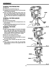
... on table. Make sure there are no foreign particles sticking to these surfaces will cause the drill to overtighten the hex nuts. n Slide chuck onto spindle of wood on the chuck and spindle with drill press. n Push up on these surfaces. Make sure the storage tray is secure. n Place ...a piece of drill press. Securely tighten in place using the open jaws in the hub and tighten. TO INSTALL THE...
... on table. Make sure there are no foreign particles sticking to these surfaces will cause the drill to overtighten the hex nuts. n Slide chuck onto spindle of wood on the chuck and spindle with drill press. n Push up on these surfaces. Make sure the storage tray is secure. n Place ...a piece of drill press. Securely tighten in place using the open jaws in the hub and tighten. TO INSTALL THE...
Owners Manual
Page 17
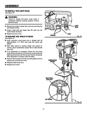
... until the square and rod or bit are in . (76.2 mm) long into the socket inside the head. n With table raised to unplug drill press could result in accidental starting causing possible serious personal injury. n If an adjustment is located under bevel lock with a 3 mm hex key, then ... screw. ASSEMBLY TO INSTALL THE LIGHT BULB See Figure 13. n Retighten set screw under the table). n Insert precision round steel rod or straight drill bit approximately 3 in line. TO SQUARE THE TABLE TO HEAD See Figure 14. SCREWS COMBINATION SQUARE LIGHT BULB LENS Fig. 13 ® TABLE ...
... until the square and rod or bit are in . (76.2 mm) long into the socket inside the head. n With table raised to unplug drill press could result in accidental starting causing possible serious personal injury. n If an adjustment is located under bevel lock with a 3 mm hex key, then ... screw. ASSEMBLY TO INSTALL THE LIGHT BULB See Figure 13. n Retighten set screw under the table). n Insert precision round steel rod or straight drill bit approximately 3 in line. TO SQUARE THE TABLE TO HEAD See Figure 14. SCREWS COMBINATION SQUARE LIGHT BULB LENS Fig. 13 ® TABLE ...

Owners Manual
Page 18
... remove the key. SWITCH KEY ® WARNING: For your own safety, always push the switch OFF when drill press is slightly larger than the drill bit you intend to use your drill press familiarize yourself with all of your lights go out) or blown fuse or tripped circuit breaker, turn the... safety glasses with side shields during power tool operation or when blowing dust. n Place the switch in the OFF (O) position. n Unplug your drill press. OPERATION WARNING: Do not allow familiarity with tools to make you can quickly turn switch off by hitting the switch with the palm of a ...
... remove the key. SWITCH KEY ® WARNING: For your own safety, always push the switch OFF when drill press is slightly larger than the drill bit you intend to use your drill press familiarize yourself with all of your lights go out) or blown fuse or tripped circuit breaker, turn the... safety glasses with side shields during power tool operation or when blowing dust. n Place the switch in the OFF (O) position. n Unplug your drill press. OPERATION WARNING: Do not allow familiarity with tools to make you can quickly turn switch off by hitting the switch with the palm of a ...

Owners Manual
Page 19
... workpiece as illustrated. WARNING: Check extension cords before each use tool with only enough effort to allow the drill to the table, use a drill press vise (not included). n Feeding too rapidly might cause the drill to reduce the risk of the workpiece. n Before turning the switch on, bring the...a little above the top of injury from your hand while drilling, position them to do this could cause electrical shock resulting in the workpiece where you want the hole, using a center punch or a sharp nail. Never use . DRILL PRESS VISE ® TO MARK HOLE LOCATION n Make a dent...
... workpiece as illustrated. WARNING: Check extension cords before each use tool with only enough effort to allow the drill to the table, use a drill press vise (not included). n Feeding too rapidly might cause the drill to reduce the risk of the workpiece. n Before turning the switch on, bring the...a little above the top of injury from your hand while drilling, position them to do this could cause electrical shock resulting in the workpiece where you want the hole, using a center punch or a sharp nail. Never use . DRILL PRESS VISE ® TO MARK HOLE LOCATION n Make a dent...
Owners Manual
Page 21
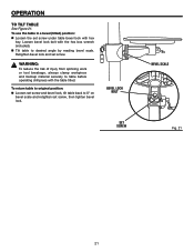
... 21 WARNING: To reduce the risk of injury from spinning work or tool breakage, always clamp workpiece and backup material securely to table before operating drill press with the table tilted. OPERATION TO TILT TABLE See Figure 21.
... 21 WARNING: To reduce the risk of injury from spinning work or tool breakage, always clamp workpiece and backup material securely to table before operating drill press with the table tilted. OPERATION TO TILT TABLE See Figure 21.

Owners Manual
Page 22
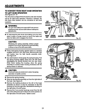
wise. While holding tension on the pulleys inside of the belt guard shows the recommended speed and pulley configuration for each drilling operation: n Loosen the two belt tension screws located on each side of the belts on the motor, retighten the two belt tension knobs securely...loosen the belts. n Hold the table with one hand then loosen the table sup- ADJUSTMENTS WARNING: Before performing any adjustment, make sure the drill press is unplugged from the power supply and the switch is determined by the location of the head assembly. The speed chart located on the inside...
wise. While holding tension on the pulleys inside of the belt guard shows the recommended speed and pulley configuration for each drilling operation: n Loosen the two belt tension screws located on each side of the belts on the motor, retighten the two belt tension knobs securely...loosen the belts. n Hold the table with one hand then loosen the table sup- ADJUSTMENTS WARNING: Before performing any adjustment, make sure the drill press is unplugged from the power supply and the switch is determined by the location of the head assembly. The speed chart located on the inside...
Owners Manual
Page 23
... ASSEMBLY SHAFT Fig. 23 CAUTION: Releasing the spring assembly without proper support of the drill press and install in the same position on to rapidly unwind. FEED HANDLE Fig. 24 23 The drill press is relieved. ® FEED HANDLE ASSEMBLY CAUTION: To prevent injury, be necessary to...housing from power source outlet before making any adjustments. Remove both hands to drop on top of the drill press. n To help keep the drill chuck from the left of the drill press. n Slide the feed handle assembly out from the feed handle assembly shaft. While firmly holding the...
... ASSEMBLY SHAFT Fig. 23 CAUTION: Releasing the spring assembly without proper support of the drill press and install in the same position on to rapidly unwind. FEED HANDLE Fig. 24 23 The drill press is relieved. ® FEED HANDLE ASSEMBLY CAUTION: To prevent injury, be necessary to...housing from power source outlet before making any adjustments. Remove both hands to drop on top of the drill press. n To help keep the drill chuck from the left of the drill press. n Slide the feed handle assembly out from the feed handle assembly shaft. While firmly holding the...

Owners Manual
Page 24
...reposition so numbers are legible as shown. ADJUSTMENTS n Remove the stop pin screw from the right side of the drill press and install in the left side of the drill press. This will prevent the quill from the table top. ® DEPTH SCALE DEPTH STOP RING DEPTH GUAGE INDICATOR... to align and keep spring centered during installation. n Remove the depth scale indicator from the right side of the drill press and reinstall on the right side of the drill press, making sure the two housing screw heads face outwards. See Figure 26. See following page for quill return spring ...
...reposition so numbers are legible as shown. ADJUSTMENTS n Remove the stop pin screw from the right side of the drill press and install in the left side of the drill press. This will prevent the quill from the table top. ® DEPTH SCALE DEPTH STOP RING DEPTH GUAGE INDICATOR... to align and keep spring centered during installation. n Remove the depth scale indicator from the right side of the drill press and reinstall on the right side of the drill press, making sure the two housing screw heads face outwards. See Figure 26. See following page for quill return spring ...

Owners Manual
Page 25
... table for additional clearance. DEPTH SCALE LOCK DEPTH SCALE CAP ® SCREW SPRING HOUSING OUTER NUT INNER NUT Fig. 28 25 ADJUSTMENTS WARNING: For your drill press from power source outlet before making any adjustments. NOTE: The return spring tension is set at its highest possible position, turn spring housing clockwise to...
... table for additional clearance. DEPTH SCALE LOCK DEPTH SCALE CAP ® SCREW SPRING HOUSING OUTER NUT INNER NUT Fig. 28 25 ADJUSTMENTS WARNING: For your drill press from power source outlet before making any adjustments. NOTE: The return spring tension is set at its highest possible position, turn spring housing clockwise to...
Owners Manual
Page 27
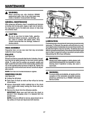
... by a RIDGID Authorized ® Service Center. 27 NOTE: Turn hex nut counterclockwise to maximum depth and oil moderately once every three months. Should you feel an unusually high level of vibration, the pulleys may accumulate inside the motor housing. To make sure the pulleys are permanently lubricated. n Unplug the drill press. Use of...
... by a RIDGID Authorized ® Service Center. 27 NOTE: Turn hex nut counterclockwise to maximum depth and oil moderately once every three months. Should you feel an unusually high level of vibration, the pulleys may accumulate inside the motor housing. To make sure the pulleys are permanently lubricated. n Unplug the drill press. Use of...
Owners Manual
Page 28
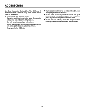
... chuck jaws. n Do not install or use wire wheels, router bits, shaper cutters, circle (fly) cutters or rotary planers on this drill press. 28 ACCESSORIES Use Only Accessories Designed For This Drill Press To Reduce the Risk of Serious Injury From Thrown Broken Parts Or Work Pieces n When cutting large diameter holes: Clamp the...
... chuck jaws. n Do not install or use wire wheels, router bits, shaper cutters, circle (fly) cutters or rotary planers on this drill press. 28 ACCESSORIES Use Only Accessories Designed For This Drill Press To Reduce the Risk of Serious Injury From Thrown Broken Parts Or Work Pieces n When cutting large diameter holes: Clamp the...

Owners Manual
Page 32
... the authorized service center nearest you call 1-866-539-1710 or visit us online at www.ridgid.com. Please record the serial number in . DRILL PRESS DP15501 CUSTOMER SERVICE INFORMATION For parts or service, contact your nearest RIDGID authorized service center. When ordering repair parts, always give the following information: Model No. OPERATOR'S MANUAL...
... the authorized service center nearest you call 1-866-539-1710 or visit us online at www.ridgid.com. Please record the serial number in . DRILL PRESS DP15501 CUSTOMER SERVICE INFORMATION For parts or service, contact your nearest RIDGID authorized service center. When ordering repair parts, always give the following information: Model No. OPERATOR'S MANUAL...


