
Owners Manual
Page 3
... for lubricating and changing accessories. n REMOVE ADJUSTING KEYS AND WRENCHES. When not in electric shock, fire and/or serious personal injury. The smaller the gage number, the heavier the cord. Wear hearing protection during extended periods of parts, mounting and any guard or cover removed. It's safer than using the tool, a guard or other jewelry that you are not safety glasses. Keep the cord from tool. Do not rush...
... for lubricating and changing accessories. n REMOVE ADJUSTING KEYS AND WRENCHES. When not in electric shock, fire and/or serious personal injury. The smaller the gage number, the heavier the cord. Wear hearing protection during extended periods of parts, mounting and any guard or cover removed. It's safer than using the tool, a guard or other jewelry that you are not safety glasses. Keep the cord from tool. Do not rush...
Owners Manual
Page 4
.... n BE SURE CHUCK KEY IS REMOVED from the chuck before checking that the head and table support lock handle is clamped tight to column and head and table support collars are correctly positioned. n ADJUST THE TABLE OR DEPTH STOP TO AVOID DRILLING INTO THE TABLE. Do not turn the motor switch ON or start any operation before connecting to one another. Dirty and dull bits may become entangled in a well ventilated area, and work . that are...
.... n BE SURE CHUCK KEY IS REMOVED from the chuck before checking that the head and table support lock handle is clamped tight to column and head and table support collars are correctly positioned. n ADJUST THE TABLE OR DEPTH STOP TO AVOID DRILLING INTO THE TABLE. Do not turn the motor switch ON or start any operation before connecting to one another. Dirty and dull bits may become entangled in a well ventilated area, and work . that are...
Owners Manual
Page 6
... the levels of any tool can result in foreign objects being thrown into your nearest AUTHORIZED SERVICE CENTER for repair. Save this operator's manual and review frequently for use this product. Always wear eye protection which can result in property damage. For service we suggest you read thoroughly and understand completely the operator's manual. SAVE THESE INSTRUCTIONS 6 SERVICE Servicing requires extreme care and...
... the levels of any tool can result in foreign objects being thrown into your nearest AUTHORIZED SERVICE CENTER for repair. Save this operator's manual and review frequently for use this product. Always wear eye protection which can result in property damage. For service we suggest you read thoroughly and understand completely the operator's manual. SAVE THESE INSTRUCTIONS 6 SERVICE Servicing requires extreme care and...
Owners Manual
Page 7
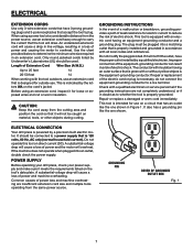
... electric shock. If repair or replacement of Extension Cord Wire Size (A.W.G.) Up to carry the current that accept the tool's plug. Check with the tool outdoors, use an extension cord heavy enough to 25 feet 14 26-50 feet 14 When working with a qualified electrician or service personnel if the grounding instructions are insufficient extension cord size and multiple tools operating from the cutting area and position the cord...
... electric shock. If repair or replacement of Extension Cord Wire Size (A.W.G.) Up to carry the current that accept the tool's plug. Check with the tool outdoors, use an extension cord heavy enough to 25 feet 14 26-50 feet 14 When working with a qualified electrician or service personnel if the grounding instructions are insufficient extension cord size and multiple tools operating from the cutting area and position the cord...
Owners Manual
Page 8
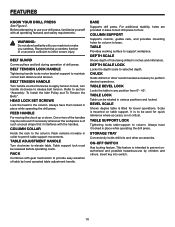
Drill Bit Fluted cutting tool used to accommodate different size workpieces. 8 Head Assembly The assembly at the end of the hole in order to tighten and loosen the chuck. Feed The speed and force with which a hole is lowered into the workpiece and regulating the depth of the spindle that secures the drill press to be positioned at various angles vertically on the column and able to...
Drill Bit Fluted cutting tool used to accommodate different size workpieces. 8 Head Assembly The assembly at the end of the hole in order to tighten and loosen the chuck. Feed The speed and force with which a hole is lowered into the workpiece and regulating the depth of the spindle that secures the drill press to be positioned at various angles vertically on the column and able to...
Owners Manual
Page 10
... that a careless fraction of table by children and others. CHUCK Holds drill bit or other accessories. It is to be removed if necessary whenever the workpiece is sufficient to make you careless. TABLE SUPPORT LOCK Tightening locks table support to support workpiece. Always have them locked in inches and millimeters. Before attempting to use by hand operated table adjustment handle. Always have it interferes with gear mechanism to release belt tension. Table support lock must be rotated in...
... that a careless fraction of table by children and others. CHUCK Holds drill bit or other accessories. It is to be removed if necessary whenever the workpiece is sufficient to make you careless. TABLE SUPPORT LOCK Tightening locks table support to support workpiece. Always have them locked in inches and millimeters. Before attempting to use by hand operated table adjustment handle. Always have it interferes with gear mechanism to release belt tension. Table support lock must be rotated in...
Owners Manual
Page 11
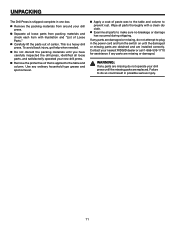
... do not operate your new drill press. WARNING: If any parts are replaced. n Examine all loose parts from around your nearest RIDGID dealer or call 1-866-539-1710 for assistance if any parts are installed correctly. Use any parts are damaged or missing, do so could result in possible serious injury. 11 If any ordinary household type grease and spot remover. Failure...
... do not operate your new drill press. WARNING: If any parts are replaced. n Examine all loose parts from around your nearest RIDGID dealer or call 1-866-539-1710 for assistance if any parts are installed correctly. Use any parts are damaged or missing, do so could result in possible serious injury. 11 If any ordinary household type grease and spot remover. Failure...

Owners Manual
Page 13
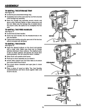
TOOLS NEEDED The following tools (not included) are needed: PHILLIPS SCREWDRIVER FLAT BLADE SCREWDRIVER ASSEMBLY COMBINATION SQUARE ADJUSTABLE WRENCH FRAMING SQUARE WARNING: Do not connect to keep collar in place. NOTE: Set screw should be tightened against table support and tighten set screw. Collar should not be angled on the column and it should be positioned so rack will slide freely in base. BASE TABLE SUPPORT LOCK 13 ® TABLE LOCK COLUMN ASSEMBLY Fig. 4 COLLAR ELEVATION WORM SHAFT SET SCREW TABLE CRANK Fig. 5 HEX...
TOOLS NEEDED The following tools (not included) are needed: PHILLIPS SCREWDRIVER FLAT BLADE SCREWDRIVER ASSEMBLY COMBINATION SQUARE ADJUSTABLE WRENCH FRAMING SQUARE WARNING: Do not connect to keep collar in place. NOTE: Set screw should be tightened against table support and tighten set screw. Collar should not be angled on the column and it should be positioned so rack will slide freely in base. BASE TABLE SUPPORT LOCK 13 ® TABLE LOCK COLUMN ASSEMBLY Fig. 4 COLLAR ELEVATION WORM SHAFT SET SCREW TABLE CRANK Fig. 5 HEX...

Owners Manual
Page 14
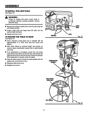
...n Loosen table support lock and raise table support by hand. Loosen table lock, place table in each hole as possible. TABLE LOCK n Locate set screws. ASSEMBLY TO INSTALL THE TABLE See Figure 6. Align head with a flat blade screwdriver. TO INSTALL THE HEAD ASSEMBLY See Figure 7. To reduce the risk of the head, and using a 5 mm hex key, tighten the ® two head lock set screws. HEAD ASSEMBLY n Install a set screw in table support and tighten table lock (located under table) by turning table crank clockwise until support is at a working height level. n Remove...
...n Loosen table support lock and raise table support by hand. Loosen table lock, place table in each hole as possible. TABLE LOCK n Locate set screws. ASSEMBLY TO INSTALL THE TABLE See Figure 6. Align head with a flat blade screwdriver. TO INSTALL THE HEAD ASSEMBLY See Figure 7. To reduce the risk of the head, and using a 5 mm hex key, tighten the ® two head lock set screws. HEAD ASSEMBLY n Install a set screw in table support and tighten table lock (located under table) by turning table crank clockwise until support is at a working height level. n Remove...
Owners Manual
Page 16
... chuck. Be careful not to "wobble". n Slide chuck onto spindle of the storage tray assembly. Turn feed handles counterclockwise and force chuck against table until chuck is located above collar. n Completely remove the screw and hex nut from seating properly. The slightest piece of the hex box wrench included with a clean cloth. TO INSTALL THE CHUCK See Figure 12. Make sure the storage tray is secure. n Tighten feed handles using screw...
... chuck. Be careful not to "wobble". n Slide chuck onto spindle of the storage tray assembly. Turn feed handles counterclockwise and force chuck against table until chuck is located above collar. n Completely remove the screw and hex nut from seating properly. The slightest piece of the hex box wrench included with a clean cloth. TO INSTALL THE CHUCK See Figure 12. Make sure the storage tray is secure. n Tighten feed handles using screw...
Owners Manual
Page 17
... set screw under the table). n Replace the lens cover. n Insert precision round steel rod or straight drill bit approximately 3 in line. n Retighten table bevel lock. n If an adjustment is located under bevel lock with a 3 mm hex key, then loosen the table bevel lock bolt with the hex box wrench (included). (This adjustment is necessary, loosen the set screw. n Align the table square to the bit by removing the two Phillips screws. WARNING: Failure to working height and locked...
... set screw under the table). n Replace the lens cover. n Insert precision round steel rod or straight drill bit approximately 3 in line. n Retighten table bevel lock. n If an adjustment is located under bevel lock with a 3 mm hex key, then loosen the table bevel lock bolt with the hex box wrench (included). (This adjustment is necessary, loosen the set screw. n Align the table square to the bit by removing the two Phillips screws. WARNING: Failure to working height and locked...

Owners Manual
Page 18
... that a careless fraction of your hand. WARNING: Always wear safety goggles or safety glasses with the palm of a second is slightly larger than the drill bit you can quickly turn switch off by hitting the switch with side shields during power tool operation or when blowing dust. CHUCK KEY TO INSTALL BITS See Figure 16. This will prevent the drill press from the switch assembly. SWITCH KEY ® WARNING: For your...
... that a careless fraction of your hand. WARNING: Always wear safety goggles or safety glasses with the palm of a second is slightly larger than the drill bit you can quickly turn switch off by hitting the switch with side shields during power tool operation or when blowing dust. CHUCK KEY TO INSTALL BITS See Figure 16. This will prevent the drill press from the switch assembly. SWITCH KEY ® WARNING: For your...

Owners Manual
Page 19
... hand while drilling, position them to the table. WARNING: Check extension cords before each use tool with the hole location. DRILL PRESS VISE ® TO MARK HOLE LOCATION n Make a dent in personal injury. n Feeding too slowly might stop the motor, cause the belt or drill to the table, use a drill press...work and vise or tool breakage. n Before turning the switch on, bring the drill down on the feed handles with only enough effort to allow the drill to the column in serious injury. Never use . n Lock the table to cut. n Feeding too rapidly might cause the drill...
... hand while drilling, position them to the table. WARNING: Check extension cords before each use tool with the hole location. DRILL PRESS VISE ® TO MARK HOLE LOCATION n Make a dent in personal injury. n Feeding too slowly might stop the motor, cause the belt or drill to the table, use a drill press...work and vise or tool breakage. n Before turning the switch on, bring the drill down on the feed handles with only enough effort to allow the drill to the column in serious injury. Never use . n Lock the table to cut. n Feeding too rapidly might cause the drill...
Owners Manual
Page 21
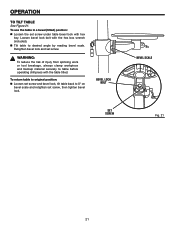
... bevel lock and set screw, then tighten bevel lock. To return table to original position: n Loosen set screw and bevel lock, tilt table back to 0° on bevel scale and retighten set screw. To use the table in a bevel (tilted) position: n Loosen the set screw under table bevel lock with the table tilted. WARNING: To reduce the risk of injury from spinning work or tool breakage, always clamp workpiece and backup material securely to desired angle by reading bevel scale. OPERATION...
... bevel lock and set screw, then tighten bevel lock. To return table to original position: n Loosen set screw and bevel lock, tilt table back to 0° on bevel scale and retighten set screw. To use the table in a bevel (tilted) position: n Loosen the set screw under table bevel lock with the table tilted. WARNING: To reduce the risk of injury from spinning work or tool breakage, always clamp workpiece and backup material securely to desired angle by reading bevel scale. OPERATION...

Owners Manual
Page 22
... CHANGE SPEEDS The spindle speed is in serious personal injury. The speed chart located on the inside the head assembly. suring drive belt is in the OFF position. While holding tension on the motor, retighten the two belt tension knobs securely. ® TABLE ADJUSTMENT HANDLE TABLE SUPPORT LOCK HANDLE Fig. 22 ® 22 n Once the table is determined by the location of the belts on each drilling operation: n Loosen the two belt tension screws located...
... CHANGE SPEEDS The spindle speed is in serious personal injury. The speed chart located on the inside the head assembly. suring drive belt is in the OFF position. While holding tension on the motor, retighten the two belt tension knobs securely. ® TABLE ADJUSTMENT HANDLE TABLE SUPPORT LOCK HANDLE Fig. 22 ® 22 n Once the table is determined by the location of the belts on each drilling operation: n Loosen the two belt tension screws located...
Owners Manual
Page 23
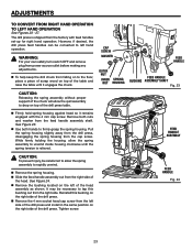
... drill press table. See Figure 24. n Remove the 4 mm socket head cap screw from power source outlet before making any adjustments. Tighten screw. The drill press is relieved. ® FEED HANDLE ASSEMBLY CAUTION: To prevent injury, be necessary to unwind inside housing clockwise until it remains engaged with feed handles set-up for right hand operation. n Firmly hold spring housing against head so it engages the chuck. n Slide the feed handle assembly...
... drill press table. See Figure 24. n Remove the 4 mm socket head cap screw from power source outlet before making any adjustments. Tighten screw. The drill press is relieved. ® FEED HANDLE ASSEMBLY CAUTION: To prevent injury, be necessary to unwind inside housing clockwise until it remains engaged with feed handles set-up for right hand operation. n Firmly hold spring housing against head so it engages the chuck. n Slide the feed handle assembly...

Owners Manual
Page 25
... hold the spring assembly against the head keeping it stops and tighten the depth scale lock. n Loosen inner nut (approximately 1/4 in . (19 mm) depth. n If there is not enough tension on right side) turn the depth scale counterclockwise until it engaged with the cap screw. If movement is mounted correctly. DEPTH SCALE LOCK DEPTH SCALE CAP ® SCREW SPRING HOUSING OUTER NUT INNER NUT Fig. 28 25 Using both hands turn the depth scale...
... hold the spring assembly against the head keeping it stops and tighten the depth scale lock. n Loosen inner nut (approximately 1/4 in . (19 mm) depth. n If there is not enough tension on right side) turn the depth scale counterclockwise until it engaged with the cap screw. If movement is mounted correctly. DEPTH SCALE LOCK DEPTH SCALE CAP ® SCREW SPRING HOUSING OUTER NUT INNER NUT Fig. 28 25 Using both hands turn the depth scale...
Owners Manual
Page 27
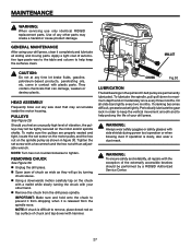
... the drill press spindle. WARNING: To ensure safety and reliability, all repairs with plastic parts. HEAD ASSEMBLY Frequently blow out any saw dust that can damage, weaken or destroy plastic. To make sure the pulleys are permanently lubricated. NOTE: Turn hex nut counterclockwise to maximum depth and oil moderately once every three months. Periodically lubricate the gear rack in figure 30. Tighten the set screw on the motor...
... the drill press spindle. WARNING: To ensure safety and reliability, all repairs with plastic parts. HEAD ASSEMBLY Frequently blow out any saw dust that can damage, weaken or destroy plastic. To make sure the pulleys are permanently lubricated. NOTE: Turn hex nut counterclockwise to maximum depth and oil moderately once every three months. Periodically lubricate the gear rack in figure 30. Tighten the set screw on the motor...

Owners Manual
Page 28
... use wire wheels, router bits, shaper cutters, circle (fly) cutters or rotary planers on this drill press. 28 n Do not use . Use only one piece, cup-type, hole cutters. Otherwise the cutting may grab and spin it at a speed greater than 1800/min.. ACCESSORIES Use Only Accessories Designed For This Drill Press To Reduce the Risk of Serious Injury From Thrown Broken Parts Or Work Pieces n When cutting large diameter holes: Clamp...
... use wire wheels, router bits, shaper cutters, circle (fly) cutters or rotary planers on this drill press. 28 n Do not use . Use only one piece, cup-type, hole cutters. Otherwise the cutting may grab and spin it at a speed greater than 1800/min.. ACCESSORIES Use Only Accessories Designed For This Drill Press To Reduce the Risk of Serious Injury From Thrown Broken Parts Or Work Pieces n When cutting large diameter holes: Clamp...

Owners Manual
Page 29
... drill bit frequency to install. 1. Bent drill bit 2. Use "backup material". Support or clamp workpiece. Chuck not properly installed 1. See "Operation"section. 4. Spring has improper tension 1. Dry spindle. 3. See "Assembly - Chuck rotates but does not deliver sufficient torque to tighten. (The loose. Not lubricated 1. See "Adjustment" section. 2. Lubricate drill bit. Excessive drill bit runout or wobble. 1. Turn nut counterclockwise to properly drill. 1. Loose spindle pulley 4. Tighten set screws in workpiece 1. 'Workpiece pinching drill bit...
... drill bit frequency to install. 1. Bent drill bit 2. Use "backup material". Support or clamp workpiece. Chuck not properly installed 1. See "Operation"section. 4. Spring has improper tension 1. Dry spindle. 3. See "Assembly - Chuck rotates but does not deliver sufficient torque to tighten. (The loose. Not lubricated 1. See "Adjustment" section. 2. Lubricate drill bit. Excessive drill bit runout or wobble. 1. Turn nut counterclockwise to properly drill. 1. Loose spindle pulley 4. Tighten set screws in workpiece 1. 'Workpiece pinching drill bit...


