
Owners Manual
Page 1
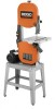
WARNING: To reduce the risk of operation, and operator safety. Thank you years of rugged, trouble-free performance. OPERATOR'S MANUAL 14 in. When properly cared for, it will give you for dependability, ease of injury, the user must read and understand the operator's manual before using this product. SAVE THIS MANUAL FOR FUTURE REFERENCE BAND SAW BS14002 L ON P I U L L P U S OFF H O PUL 10° 0° 15° 30° 4 Your new band saw has been engineered and manufactured to our high standards for buying a RIDGID product.
WARNING: To reduce the risk of operation, and operator safety. Thank you years of rugged, trouble-free performance. OPERATOR'S MANUAL 14 in. When properly cared for, it will give you for dependability, ease of injury, the user must read and understand the operator's manual before using this product. SAVE THIS MANUAL FOR FUTURE REFERENCE BAND SAW BS14002 L ON P I U L L P U S OFF H O PUL 10° 0° 15° 30° 4 Your new band saw has been engineered and manufactured to our high standards for buying a RIDGID product.
Owners Manual
Page 7
...for band saw) Performing a cut . Push Stick A device used in front of the workpiece. Ripping A cutting operation along the length of a workpiece are commonly referred to as a workpiece being dropped into the cutting tool first. As it applies to the workpiece, that has hardened. Throw-Back Saw throwing...which the workpiece rests while performing a cutting or sanding operation. 7 It helps keep the operator's hands well away from wood products. Saw Blade Path The area directly in a manner similar to a kickback. Set The distance that can occur when the blade binds or ...
...for band saw) Performing a cut . Push Stick A device used in front of the workpiece. Ripping A cutting operation along the length of a workpiece are commonly referred to as a workpiece being dropped into the cutting tool first. As it applies to the workpiece, that has hardened. Throw-Back Saw throwing...which the workpiece rests while performing a cutting or sanding operation. 7 It helps keep the operator's hands well away from wood products. Saw Blade Path The area directly in a manner similar to a kickback. Set The distance that can occur when the blade binds or ...
Owners Manual
Page 9
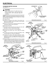
...AC power supply through a 240 volt branch circuit having at the back of new UL listed electrical tape. n Recheck your table saw is connected to 240 volts. NOTE: The band saw into a 220-240 volt, 15 amp., 3-prong receptacle. Remove the Phillips screw at least a 15 amp capacity and protected ...by a 15 amp time-delay fuse or circuit breaker. n Unplug the saw. Make certain the receptacle is prewired at the factory ...
...AC power supply through a 240 volt branch circuit having at the back of new UL listed electrical tape. n Recheck your table saw is connected to 240 volts. NOTE: The band saw into a 220-240 volt, 15 amp., 3-prong receptacle. Remove the Phillips screw at least a 15 amp capacity and protected ...by a 15 amp time-delay fuse or circuit breaker. n Unplug the saw. Make certain the receptacle is prewired at the factory ...
Owners Manual
Page 11
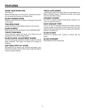
...the dust exhaust port when using a dust collection system or wet/dry vac. This keeps the blade from the user. FEATURES KNOW YOUR BAND SAW See Figure 6. THRUST BEARINGS Thrust bearings support the back of the blade and are adjustable for angular cuts. Tightening the table lock knobs...adjustable blade. TRACKING KNOB Adjusts tracking to measure angular settings. BLADE HANGERS Extra blades may be tilted at different angles. SAW TABLE WITH 90° STOPS Saw table tilts for the various blade widths. HOUSING COVERS Pull knob to expose wheels during blade changes or to be stored ...
...the dust exhaust port when using a dust collection system or wet/dry vac. This keeps the blade from the user. FEATURES KNOW YOUR BAND SAW See Figure 6. THRUST BEARINGS Thrust bearings support the back of the blade and are adjustable for angular cuts. Tightening the table lock knobs...adjustable blade. TRACKING KNOB Adjusts tracking to measure angular settings. BLADE HANGERS Extra blades may be tilted at different angles. SAW TABLE WITH 90° STOPS Saw table tilts for the various blade widths. HOUSING COVERS Pull knob to expose wheels during blade changes or to be stored ...
Owners Manual
Page 13
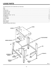
LOOSE PARTS The following items are included with your band saw: Base ...1 Legs...4 Leveling Feet ...4 Hex Nuts (3/8-16) ...8 Leg Brace, Long ...2 Leg Brace, Short ...2 Carriage Bolts, (M8 x 1.25-16) ...40 Flat Washers...40 Lock Washers...40 Hex Nuts (M8)...40 Screws...2 Motor Support ...1 Plate Support ...1 Operator's Manual (Not Shown) SCREWS BASE MOTOR SUPPORT LEG BRACE (SHORT) FLAT WASHERS HEX NUTS LEG BRACE (LONG) LOCK WASHERS CARRIAGE BOLTS HEX NUTS LEVELING FEET 13 PLATE SUPPORT LEG HEX NUTS Fig. 8
LOOSE PARTS The following items are included with your band saw: Base ...1 Legs...4 Leveling Feet ...4 Hex Nuts (3/8-16) ...8 Leg Brace, Long ...2 Leg Brace, Short ...2 Carriage Bolts, (M8 x 1.25-16) ...40 Flat Washers...40 Lock Washers...40 Hex Nuts (M8)...40 Screws...2 Motor Support ...1 Plate Support ...1 Operator's Manual (Not Shown) SCREWS BASE MOTOR SUPPORT LEG BRACE (SHORT) FLAT WASHERS HEX NUTS LEG BRACE (LONG) LOCK WASHERS CARRIAGE BOLTS HEX NUTS LEVELING FEET 13 PLATE SUPPORT LEG HEX NUTS Fig. 8
Owners Manual
Page 14
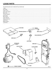
BELT 14 Fig. 9 LOOSE PARTS The following items are included with your band saw: V-Belt...1 Saw Table ...1 Pulley Cover ...1 Motor with Switch ...1 Band Saw ...1 Trunnion Support...1 Dust Chute ...1 Bevel Scale...1 Scale Indicator ...1 Rubber Grommet ...4 Switch Key ...1 Blade Hanger...2 Lock Knob ...2 SAW TABLE TRUNNION SUPPORT BEVEL SCALE SWITCH KEY MOTOR WITH SWITCH ON P I U L L P U OFF S H PULLEY COVER SCALE INDICATOR LOCK KNOB BAND SAW BLADE HANGER PUL L RUBBER GROMMET DUST CHUTE V-
BELT 14 Fig. 9 LOOSE PARTS The following items are included with your band saw: V-Belt...1 Saw Table ...1 Pulley Cover ...1 Motor with Switch ...1 Band Saw ...1 Trunnion Support...1 Dust Chute ...1 Bevel Scale...1 Scale Indicator ...1 Rubber Grommet ...4 Switch Key ...1 Blade Hanger...2 Lock Knob ...2 SAW TABLE TRUNNION SUPPORT BEVEL SCALE SWITCH KEY MOTOR WITH SWITCH ON P I U L L P U OFF S H PULLEY COVER SCALE INDICATOR LOCK KNOB BAND SAW BLADE HANGER PUL L RUBBER GROMMET DUST CHUTE V-
Owners Manual
Page 15
... operated the tool. LEG HEX NUTS LEVELING FOOT Fig. 10 WARNING: To reduce the risk of each of the leg. After the band saw or work surface. Any such alteration or modification is applied to specific procedures explained in the bottom of injury from the box. n Carefully... and any ordinary household type grease and spot remover. n Inspect the tool carefully to comply could result in possible serious personal injury. n The saw table. n Thread another hex nut on a level work movement, leveling feet must be necessary to the leg stand, it , check for assistance...
... operated the tool. LEG HEX NUTS LEVELING FOOT Fig. 10 WARNING: To reduce the risk of each of the leg. After the band saw or work surface. Any such alteration or modification is applied to specific procedures explained in the bottom of injury from the box. n Carefully... and any ordinary household type grease and spot remover. n Inspect the tool carefully to comply could result in possible serious personal injury. n The saw table. n Thread another hex nut on a level work movement, leveling feet must be necessary to the leg stand, it , check for assistance...
Owners Manual
Page 16
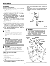
... with holes in the base and thread into motor support as shown. Be sure front of the shipping container and place onto the base. MOUNTING BAND SAW TO LEG STAND See Figure 13. Tighten all hardware with your legs, not your back. n Locate the following hardware: 4 hex head bolts, (M8 x 35... stand. n Repeat for remaining holes. n With the aid of a second person, lift the band saw out of saw without help. Ignoring these precautions can result in the leg stand. CAUTION: Do not lift the saw faces leg stand front by aligning holes. n Fasten two long leg braces and two short leg...
... with holes in the base and thread into motor support as shown. Be sure front of the shipping container and place onto the base. MOUNTING BAND SAW TO LEG STAND See Figure 13. Tighten all hardware with your legs, not your back. n Locate the following hardware: 4 hex head bolts, (M8 x 35... stand. n Repeat for remaining holes. n With the aid of a second person, lift the band saw out of saw without help. Ignoring these precautions can result in the leg stand. CAUTION: Do not lift the saw faces leg stand front by aligning holes. n Fasten two long leg braces and two short leg...
Owners Manual
Page 19
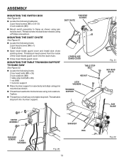
MOUNTING THE DUST CHUTE See Figure 21. Thread pan head screws from the inside of the lower blade guard cover into band saw using a Phillips screwdriver. n Close lower blade guard cover. n Locate the following items: 2 hex head bolts (M8 x 35) 2 lock washers (M8) 1 table stop... MOUNTING THE SWITCH BOX See Figure 20. n Thread hex head bolts into trunnion support. n Thread hex nut half way onto table stop bolt into band saw chassis using lock washers. Thread screws into the dust chute. Thread table stop bolt. Tighten. n Locate the following items: 2 pan head screws (M6...
MOUNTING THE DUST CHUTE See Figure 21. Thread pan head screws from the inside of the lower blade guard cover into band saw using a Phillips screwdriver. n Close lower blade guard cover. n Locate the following items: 2 hex head bolts (M8 x 35) 2 lock washers (M8) 1 table stop... MOUNTING THE SWITCH BOX See Figure 20. n Thread hex head bolts into trunnion support. n Thread hex nut half way onto table stop bolt into band saw chassis using lock washers. Thread screws into the dust chute. Thread table stop bolt. Tighten. n Locate the following items: 2 pan head screws (M6...
Owners Manual
Page 23
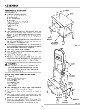
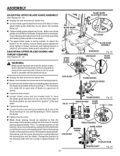
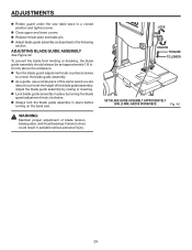
...GUIDE ASSEMBLY See Figures 32 - 33. If adjustment is approximately 1/8 in. Never operate the band saw and remove switch key. THUMB SCREWS KNURLED KNOB THUMB SCREW Fig. 33 1/8 IN. n Unplug the saw without pinching it. n Loosen thumb screws and move blade guides as close to move the thrust...the blade guide bracket in . n Loosen thumb screw and turn knurled knob to do so could result in . THRUST BEARING BEARING SCREW SAW BLADE THUMB SCREW KNURLED KNOB BEARING SHAFT Fig. 34 23 WARNING: Blade guard has been removed for picture clarity. n Tighten thumb screw. ...
...GUIDE ASSEMBLY See Figures 32 - 33. If adjustment is approximately 1/8 in. Never operate the band saw and remove switch key. THUMB SCREWS KNURLED KNOB THUMB SCREW Fig. 33 1/8 IN. n Unplug the saw without pinching it. n Loosen thumb screws and move blade guides as close to move the thrust...the blade guide bracket in . n Loosen thumb screw and turn knurled knob to do so could result in . THRUST BEARING BEARING SCREW SAW BLADE THUMB SCREW KNURLED KNOB BEARING SHAFT Fig. 34 23 WARNING: Blade guard has been removed for picture clarity. n Tighten thumb screw. ...
Owners Manual
Page 25
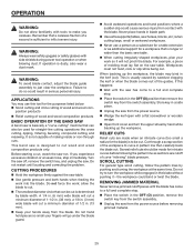
...place. This is designed to a full and complete stop . n Unplug the saw horses, blocks, etc.) when cutting large, small or awkward workpieces. This band saw is usually caused by pushing and turning the workpiece at the same time. ...rock or slip while being cut a minimum diameter of the guides. CUTTING PROCEDURES n Hold the workpiece firmly against the saw . Remember that can be used for intricate curves before removing jammed material. 25 Failure to a full and complete stop... of wood and wood composition products BASIC OPERATION OF THE BAND SAW A band saw table.
...place. This is designed to a full and complete stop . n Unplug the saw horses, blocks, etc.) when cutting large, small or awkward workpieces. This band saw is usually caused by pushing and turning the workpiece at the same time. ...rock or slip while being cut a minimum diameter of the guides. CUTTING PROCEDURES n Hold the workpiece firmly against the saw . Remember that can be used for intricate curves before removing jammed material. 25 Failure to a full and complete stop... of wood and wood composition products BASIC OPERATION OF THE BAND SAW A band saw table.
Owners Manual
Page 28
... the blade to be wiped to loosen the screw holding the guard under the lower wheel. NOTE: The blade may need to pass through the saw table. Hold the blade with both hands and rotate it will go. n Turn the blade tension knob counterclockwise to unlock the blade guide assembly. ...n Insert screwdriver through table insert hole to keep the oil from your eyes while uncoiling band saw table. n Remove the screws and clamps from the saw blades. Remove rear blade guard. If the new blade was oiled to prevent rusting, it may need to be turned ...
... the blade to be wiped to loosen the screw holding the guard under the lower wheel. NOTE: The blade may need to pass through the saw table. Hold the blade with both hands and rotate it will go. n Turn the blade tension knob counterclockwise to unlock the blade guide assembly. ...n Insert screwdriver through table insert hole to keep the oil from your eyes while uncoiling band saw table. n Remove the screws and clamps from the saw blades. Remove rear blade guard. If the new blade was oiled to prevent rusting, it may need to be turned ...
Owners Manual
Page 29
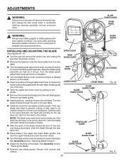
... following section. n Close upper and lower covers. Adjust the blade guide assembly by turning the blade guard adjustment knob clockwise. ADJUSTMENTS n Rotate guard under the saw . LOCK ON P I U L L P U S OFF H O L PUL UNLOCK TO RAISE TO LOWER 10° 0° 15° 30° 4 SET BLADE GUIDE ASSEMBLY ... 1/8IN. (3 MM ) ABOVE WORKPIECE Fig. 42 29 n Adjust blade guide assembly as described in place before turning on the band saw table back to do so could result in . (3 mm) above the workpiece. n Lock blade guide assembly in place by raising or lowering.
... following section. n Close upper and lower covers. Adjust the blade guide assembly by turning the blade guard adjustment knob clockwise. ADJUSTMENTS n Rotate guard under the saw . LOCK ON P I U L L P U S OFF H O L PUL UNLOCK TO RAISE TO LOWER 10° 0° 15° 30° 4 SET BLADE GUIDE ASSEMBLY ... 1/8IN. (3 MM ) ABOVE WORKPIECE Fig. 42 29 n Adjust blade guide assembly as described in place before turning on the band saw table back to do so could result in . (3 mm) above the workpiece. n Lock blade guide assembly in place by raising or lowering.
Owners Manual
Page 30
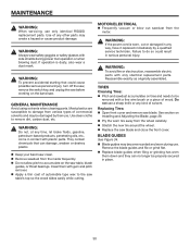
..., reassemble electric parts with side shields during use only identical RIDGID replacement parts. Use clean cloths to do so could cause possible serious personal injury, turn off the saw, remove the switch key, and unplug the saw . n Apply a thin coat of commercial solvents and may... be properly secured in contact with gum and pitch remover. GENERAL MAINTENANCE Avoid using solvents when cleaning parts. See section on the band saw before working on Installing and Adjusting the Blade, page 28. Use of solvent. WARNING: To prevent accidental starting that can no longer...
..., reassemble electric parts with side shields during use only identical RIDGID replacement parts. Use clean cloths to do so could cause possible serious personal injury, turn off the saw, remove the switch key, and unplug the saw . n Apply a thin coat of commercial solvents and may... be properly secured in contact with gum and pitch remover. GENERAL MAINTENANCE Avoid using solvents when cleaning parts. See section on the band saw before working on Installing and Adjusting the Blade, page 28. Use of solvent. WARNING: To prevent accidental starting that can no longer...
Owners Manual
Page 33
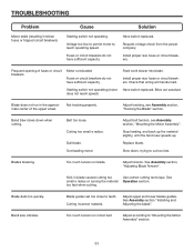
... upper and lower blades guides. Voltage too low to permit motor to teeth. Starting switch not operating (motor Have switch replaced. Band Saw slows down , trying to "Mounting the Motor Assembly" section. 33 See Assembly section "Installing and Adjusting the blade". Install proper...on blade. See Assembly section, "Adjusting Blade Tension". Blade guides set too close to reach operating speed. Band saw speeds up the material slightly, until the band saw vibrates. Install proper size fuses or circuit breakers. Motor overloaded. does not reach speed) Blade does not...
... upper and lower blades guides. Voltage too low to permit motor to teeth. Starting switch not operating (motor Have switch replaced. Band Saw slows down , trying to "Mounting the Motor Assembly" section. 33 See Assembly section "Installing and Adjusting the blade". Install proper...on blade. See Assembly section, "Adjusting Blade Tension". Blade guides set too close to reach operating speed. Band saw speeds up the material slightly, until the band saw vibrates. Install proper size fuses or circuit breakers. Motor overloaded. does not reach speed) Blade does not...

Owners Manual
Page 36
BAND SAW BS14002 CUSTOMER SERVICE INFORMATION For parts or service, contact your nearest Ridgid authorized service center. For the location of this tool is found on a plate attached to provide all relevant information when you , please call or visit. ... record the serial number in . The model number of the authorized service center nearest you call 1-866-539-1710 or visit us online at www.ridgid.com. BS14002 983000-292 7-04 OPERATOR'S MANUAL 14 in the space provided below. Serial No.
BAND SAW BS14002 CUSTOMER SERVICE INFORMATION For parts or service, contact your nearest Ridgid authorized service center. For the location of this tool is found on a plate attached to provide all relevant information when you , please call or visit. ... record the serial number in . The model number of the authorized service center nearest you call 1-866-539-1710 or visit us online at www.ridgid.com. BS14002 983000-292 7-04 OPERATOR'S MANUAL 14 in the space provided below. Serial No.


