
MA 4 Amplifier Data Sheet
Page 1
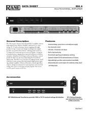
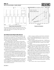
... and remote level controllable • Advanced dynamics control adjusts for the most demanding fixed installation applications. Data Sheet-1 The MA 4 excels in temperature, load impedance and sensitivity setting. The result is a truly plug-and-play amplifier that ensures excellent signal integrity at all times. DATA SHEET MA 4 MULTICHANNEL AMPLIFIER General Description The 100 watt per channel, four-channel MA 4 amplifier achieves unparalleled power density, reliability and features in automatic redundancy switching...
... and remote level controllable • Advanced dynamics control adjusts for the most demanding fixed installation applications. Data Sheet-1 The MA 4 excels in temperature, load impedance and sensitivity setting. The result is a truly plug-and-play amplifier that ensures excellent signal integrity at all times. DATA SHEET MA 4 MULTICHANNEL AMPLIFIER General Description The 100 watt per channel, four-channel MA 4 amplifier achieves unparalleled power density, reliability and features in automatic redundancy switching...
MA 4 Amplifier Data Sheet
Page 2
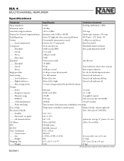
... Gain reduction release time constant Rate of gain reduction 20, 40, 60, 80 Hz dipswitch select Green Load indicator on Green Load indicator flashing Green Load indicator off 100 watts 3 to 8 Ω 20 Hz to -80 dB Active 5V high-side drive, passive pull down. MA 4 MULTICHANNEL AMPLIFIER Specifications Parameter Input impedance Maximum input Sensitivity range/resolution Remote level control range/resolution Fault flag...
... Gain reduction release time constant Rate of gain reduction 20, 40, 60, 80 Hz dipswitch select Green Load indicator on Green Load indicator flashing Green Load indicator off 100 watts 3 to 8 Ω 20 Hz to -80 dB Active 5V high-side drive, passive pull down. MA 4 MULTICHANNEL AMPLIFIER Specifications Parameter Input impedance Maximum input Sensitivity range/resolution Remote level control range/resolution Fault flag...
MA 4 Amplifier Data Sheet
Page 3
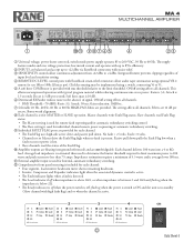
... required to limit maximum power to 100 watts and peak current to 100k Ω linear pot). ON/off setting affects all channels. The setting affects all channels. No fault = +5 volts. Each channel delivers 100 watts into a 4 or 8Ω load. RANE CORP. Impedance estimation requires a minimum of input level and sensitivity setting. 4 REMOTE DC LEVEL control ports with strain-relief. 3 SENSITIVITY controls allow audio taper attenuation using a switch, connecting Vr to Vc...
... required to limit maximum power to 100 watts and peak current to 100k Ω linear pot). ON/off setting affects all channels. The setting affects all channels. No fault = +5 volts. Each channel delivers 100 watts into a 4 or 8Ω load. RANE CORP. Impedance estimation requires a minimum of input level and sensitivity setting. 4 REMOTE DC LEVEL control ports with strain-relief. 3 SENSITIVITY controls allow audio taper attenuation using a switch, connecting Vr to Vc...

MA 4 Amplifier Data Sheet
Page 4
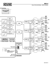
... AMPLIFIER Block Diagram INPUT CH1 INPUT CH2 INPUT CH3 INPUT CH4 IEC APPLIANCE INLET H G N 3 2 1 FUSE EMI FILTER INRUSH OVER VOLTAGE POWER-FACTORCORRECTION (100 kHz) SWITCH-MODE +25 POWER SUPPLY GND 2-SW FORWARD -25 (200 kHz) COMBINATION CONTROLLER SUPPLY CLOCK DSP ADC CH1 HIGH-PASS SENSITIVITY INPUT LIMIT REMOTE LEVEL EXPAND RMS COMPRESSOR 20-40-60-80 CH2 CH3 HIGH-PASS 20-40-60-80 SENSITIVITY INPUT LIMIT...
... AMPLIFIER Block Diagram INPUT CH1 INPUT CH2 INPUT CH3 INPUT CH4 IEC APPLIANCE INLET H G N 3 2 1 FUSE EMI FILTER INRUSH OVER VOLTAGE POWER-FACTORCORRECTION (100 kHz) SWITCH-MODE +25 POWER SUPPLY GND 2-SW FORWARD -25 (200 kHz) COMBINATION CONTROLLER SUPPLY CLOCK DSP ADC CH1 HIGH-PASS SENSITIVITY INPUT LIMIT REMOTE LEVEL EXPAND RMS COMPRESSOR 20-40-60-80 CH2 CH3 HIGH-PASS 20-40-60-80 SENSITIVITY INPUT LIMIT...
MA 4 Amplifier Data Sheet
Page 5
... EXP ON/OFF 1 0 0 20 Hz 0 1 1 1 0 1 40 HZ 60 Hz 80 Hz MODE: STANDBY: 0.0V TO 0.8V MUTE: 2.2V TO 3.0V M1 M2 M3 ON:4.2V TO 5.5V M4 AMP CLOCK SUPPLY CLOCK SUPPLY CLOCK FILTER ATT. MA 4 MULTICHANNEL AMPLIFIER EXT + - +25 CH1 FILTER CLK + M1 - OUTPUT -25 + VR2 GND EXT + +25 CH3 FILTER CLK + M3...
... EXP ON/OFF 1 0 0 20 Hz 0 1 1 1 0 1 40 HZ 60 Hz 80 Hz MODE: STANDBY: 0.0V TO 0.8V MUTE: 2.2V TO 3.0V M1 M2 M3 ON:4.2V TO 5.5V M4 AMP CLOCK SUPPLY CLOCK SUPPLY CLOCK FILTER ATT. MA 4 MULTICHANNEL AMPLIFIER EXT + - +25 CH1 FILTER CLK + M1 - OUTPUT -25 + VR2 GND EXT + +25 CH3 FILTER CLK + M3...
MA 4 Amplifier Data Sheet
Page 6
... 8 ohm load. The amplifier shall have master or slave operation determined by temperature. Automatic redundancy switching shall be a Rane Corporation Model MA 4. Load sensitive headroom meters shall provide indication of 3, 6, 12 and 24 dB of speech intelligibility. A rear panel dipswitch shall activate or deactive the compressors. The power supply design shall provide power-factor-correction with very low inrush current and overvoltage protection...
... 8 ohm load. The amplifier shall have master or slave operation determined by temperature. Automatic redundancy switching shall be a Rane Corporation Model MA 4. Load sensitive headroom meters shall provide indication of 3, 6, 12 and 24 dB of speech intelligibility. A rear panel dipswitch shall activate or deactive the compressors. The power supply design shall provide power-factor-correction with very low inrush current and overvoltage protection...

MA 4 Amplifier Data Sheet
Page 7
... those extra connections and switches intimidate you wish to operate an amplifier channel in standby. MADE IN U.S.A. RANE CORP. External +5 volts connected to ground turns the channel on , set its rear panel switch to SLAVE. MA 4 COMMERCIAL AUDIO EQUIPMENT 24TJ R 100-240V 50/60 Hz 500 WATTS INT EXT 4 OUTPUTS Class 2 Wiring INT EXT INT EXT 3 2 INT EXT 1 LOAD LOAD LOAD LOAD FAULT FLAG Active Low 4321 4321 MODE HIGH...
... those extra connections and switches intimidate you wish to operate an amplifier channel in standby. MADE IN U.S.A. RANE CORP. External +5 volts connected to ground turns the channel on , set its rear panel switch to SLAVE. MA 4 COMMERCIAL AUDIO EQUIPMENT 24TJ R 100-240V 50/60 Hz 500 WATTS INT EXT 4 OUTPUTS Class 2 Wiring INT EXT INT EXT 3 2 INT EXT 1 LOAD LOAD LOAD LOAD FAULT FLAG Active Low 4321 4321 MODE HIGH...
MA 4 Amplifier Data Sheet
Page 8
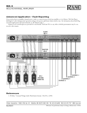
... 4 dBu MADE IN U.S.A. ZONE 1 +- MADE IN U.S.A. ZONE 4 LEVEL 46 2 8 0 10 LEVEL 46 2 8 0 10 LEVEL 46 2 8 0 10 VR 2 LEVEL 46 2 8 0 10 VOLUME REMOTES SOURCE 1 SOURCE 2 SOURCE 3 SOURCE 4 References 1. D. Bohn, "Constant-Voltage Audio Distribution Systems," RaneNote, (2000). ©Rane Corporation 10802 47th Ave. INT EXT 4 OUTPUTS Class 2 Wiring INT EXT INT EXT 3 2 INT EXT 1 LOAD LOAD LOAD LOAD MASTER MA 4 FAULT FLAG Active Low 4321 4321 MODE HIGH-PASS 20Hz 40Hz...
... 4 dBu MADE IN U.S.A. ZONE 1 +- MADE IN U.S.A. ZONE 4 LEVEL 46 2 8 0 10 LEVEL 46 2 8 0 10 LEVEL 46 2 8 0 10 VR 2 LEVEL 46 2 8 0 10 VOLUME REMOTES SOURCE 1 SOURCE 2 SOURCE 3 SOURCE 4 References 1. D. Bohn, "Constant-Voltage Audio Distribution Systems," RaneNote, (2000). ©Rane Corporation 10802 47th Ave. INT EXT 4 OUTPUTS Class 2 Wiring INT EXT INT EXT 3 2 INT EXT 1 LOAD LOAD LOAD LOAD MASTER MA 4 FAULT FLAG Active Low 4321 4321 MODE HIGH-PASS 20Hz 40Hz...
MT 4 Transformer Data Sheet / Manual
Page 1
The MT 4 comes ready-to the amplifier. This makes this arrangement presents an impedance between its 70V and 100V taps (green and yellow wires). For 25 volt audio distribution systems, the TF 4 can be used at rane.com. Depending on the rear of the 70 V system, this ideal for...frequency response within 1 dB from 40 Hz to build a tray with just the number of the TF 4 is only 1C/W and is 50 Ω. Other creative combinations are available separately, allowing the installer to 20 kHz. Features • Four channels, 100 watts, 100 / 70 volt • Input 8Ω, 100 watts...
The MT 4 comes ready-to the amplifier. This makes this arrangement presents an impedance between its 70V and 100V taps (green and yellow wires). For 25 volt audio distribution systems, the TF 4 can be used at rane.com. Depending on the rear of the 70 V system, this ideal for...frequency response within 1 dB from 40 Hz to build a tray with just the number of the TF 4 is only 1C/W and is 50 Ω. Other creative combinations are available separately, allowing the installer to 20 kHz. Features • Four channels, 100 watts, 100 / 70 volt • Input 8Ω, 100 watts...
MT 4 Transformer Data Sheet / Manual
Page 2
... flammability rated UL94V0. Secondary DC resistance: Red-Yellow < 4Ω, Red-Green < 6Ω. 3. Magnetizing Inductance: Primary: > 1H (1V, 100 Hz) 4. Schematic Figure 2. Perspective Figure 3. Mounting, Side View Insulation & Flammability 1. Max Output Power: 100 Vrms @ 1 Arms. 2. Performance Specifications 1. MT 4 MULTICHANNEL TRANSFORMER Rear Panel MT 4 MADE IN U.S.A. Insulation materials compatible with specified load 1 kHz, 100 watts 40 Hz to 20 kHz 0.1 0.2 12...
... flammability rated UL94V0. Secondary DC resistance: Red-Yellow < 4Ω, Red-Green < 6Ω. 3. Magnetizing Inductance: Primary: > 1H (1V, 100 Hz) 4. Schematic Figure 2. Perspective Figure 3. Mounting, Side View Insulation & Flammability 1. Max Output Power: 100 Vrms @ 1 Arms. 2. Performance Specifications 1. MT 4 MULTICHANNEL TRANSFORMER Rear Panel MT 4 MADE IN U.S.A. Insulation materials compatible with specified load 1 kHz, 100 watts 40 Hz to 20 kHz 0.1 0.2 12...
VR2 Remote Data Sheet / Manual
Page 1
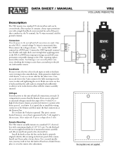
... off and use a blank Decora plate to cover the remote after adjustment. Connect the GND (ground) terminal last. For a secured installation, you know. Connect the VR2's control voltage Vc (wiper) connection(s) first. Voltages Turn the power to the unit off until all connections are free of static. Inputs are made . electrical box with the kit to mount the remote assembly and silk-screened front panel to...
... off and use a blank Decora plate to cover the remote after adjustment. Connect the GND (ground) terminal last. For a secured installation, you know. Connect the VR2's control voltage Vc (wiper) connection(s) first. Voltages Turn the power to the unit off until all connections are free of static. Inputs are made . electrical box with the kit to mount the remote assembly and silk-screened front panel to...

VR2 Remote Data Sheet / Manual
Page 2
... the factory. You may contain chemicals known to the State of the remote controls. Please contact your installation and local electrical codes. Versatile Input Port REF GND VIP pin 1....8 Silkscreen text on RPM series units. Rane Corporation does not provide or source cable. The following is recommended. PN 12907 The type of suitable cable types: CONSOLIDATED ELECTRONIC WIRE AND CABLE Plenum cable: Unshielded remote control signal cable...
... the factory. You may contain chemicals known to the State of the remote controls. Please contact your installation and local electrical codes. Versatile Input Port REF GND VIP pin 1....8 Silkscreen text on RPM series units. Rane Corporation does not provide or source cable. The following is recommended. PN 12907 The type of suitable cable types: CONSOLIDATED ELECTRONIC WIRE AND CABLE Plenum cable: Unshielded remote control signal cable...
MA 4 Amplifier Manual
Page 2
... by Rane Corporation could void the user's authority to radio or television reception, which can radiate radio frequency energy and, if not installed and used , use attachments and accessories specified by Rane. 12. NOTE: This equipment has been tested and found to qualified service personnel. Use screws through all instructions. 5. Install in a residential installation. If this apparatus from the AC mains, disconnect the power supply cord plug from...
... by Rane Corporation could void the user's authority to radio or television reception, which can radiate radio frequency energy and, if not installed and used , use attachments and accessories specified by Rane. 12. NOTE: This equipment has been tested and found to qualified service personnel. Use screws through all instructions. 5. Install in a residential installation. If this apparatus from the AC mains, disconnect the power supply cord plug from...
MA 4 Amplifier Manual
Page 4
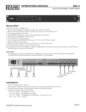
Connect balanced inputs (rear panel). 4. Turn ON the front panel power switch. Headroom (with 100 to 240 VAC, 50/60 Hz. 2. Connect speaker loads (rear panel). 9. You're good to 10 dB (rear panel). 7. Extra Credit For remote turn-on rear panel). 8. MADE IN U.S.A. The universal switching power supply works with any load), dynamics control, Fault status and Load status are indicated for each channel. Set COMPressor to go! Set SENSITIVITY controls to keep ambient temperature around the...
Connect balanced inputs (rear panel). 4. Turn ON the front panel power switch. Headroom (with 100 to 240 VAC, 50/60 Hz. 2. Connect speaker loads (rear panel). 9. You're good to 10 dB (rear panel). 7. Extra Credit For remote turn-on rear panel). 8. MADE IN U.S.A. The universal switching power supply works with any load), dynamics control, Fault status and Load status are indicated for each channel. Set COMPressor to go! Set SENSITIVITY controls to keep ambient temperature around the...

MA 4 Amplifier Manual
Page 5
... uninterrupted service. º The peak signal detector for each channel. º Audio taper attenuation with strain relief (Vref, Vcontrol, GND). º One pot may control all channels using the rear panel dipswitch. º The rms threshold is 10 dB below 55˚ C. Decay is 3 dB per second decay. • Average load impedance is estimated and used to determine the Limiter threshold setting...
... uninterrupted service. º The peak signal detector for each channel. º Audio taper attenuation with strain relief (Vref, Vcontrol, GND). º One pot may control all channels using the rear panel dipswitch. º The rms threshold is 10 dB below 55˚ C. Decay is 3 dB per second decay. • Average load impedance is estimated and used to determine the Limiter threshold setting...
MA 4 Amplifier Manual
Page 6
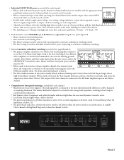
... peak signal level is in standby (Slave channel with high-side active drive and passive pull down -+ pulls -+ the -+- • ºIndWivhiednuaalfFauAlUt iLsTdMRAAeFNDtEELeCIcNAOtRUeGP.d.S.Apo. Master and Slave front panel power switches must be ON. 100-240V FOR CONTINUED GROUNDING PROTECTION DO NOT REMOVE º When a fault is detected on a Master amplifi5e0r/6c0hHaz n50n0eWlA,TTtShatTHcIhS SaCnRnEWe.l is shut down ) operation using the rear panel dipswitch. º Master channels...
... peak signal level is in standby (Slave channel with high-side active drive and passive pull down -+ pulls -+ the -+- • ºIndWivhiednuaalfFauAlUt iLsTdMRAAeFNDtEELeCIcNAOtRUeGP.d.S.Apo. Master and Slave front panel power switches must be ON. 100-240V FOR CONTINUED GROUNDING PROTECTION DO NOT REMOVE º When a fault is detected on a Master amplifi5e0r/6c0hHaz n50n0eWlA,TTtShatTHcIhS SaCnRnEWe.l is shut down ) operation using the rear panel dipswitch. º Master channels...

MA 4 Amplifier Manual
Page 7
... FAX 425-347-7757 WEB rane.com Manual-4 All features & specifications subject to these inputs (diagram at right). External +5 volts connected to the FAULT FLAG holds the amplifier in low power standby with remote turn-on, set it to ground turns the channel on Fault Flag operation, see page Manual-3. MA 4 COMMERCIAL AUDIO EQUIPMENT 24TJ R 100-240V 50/60 Hz 500 WATTS INT EXT 4 OUTPUTS Class 2 Wiring INT EXT INT EXT...
... FAX 425-347-7757 WEB rane.com Manual-4 All features & specifications subject to these inputs (diagram at right). External +5 volts connected to the FAULT FLAG holds the amplifier in low power standby with remote turn-on, set it to ground turns the channel on Fault Flag operation, see page Manual-3. MA 4 COMMERCIAL AUDIO EQUIPMENT 24TJ R 100-240V 50/60 Hz 500 WATTS INT EXT 4 OUTPUTS Class 2 Wiring INT EXT INT EXT...