
Installation Manual
Page 1
... for the wall mount plate to be capable of supporting the combined weight of this mount with the maximum weight of your sales receipt to obtain warranty parts and service and for proof of two people are required for installation. Use with heavier than 40" could cause the mount to install this package and read the installation instructions carefully. Consult the owner's manual for your television set, please...
... for the wall mount plate to be capable of supporting the combined weight of this mount with the maximum weight of your sales receipt to obtain warranty parts and service and for proof of two people are required for installation. Use with heavier than 40" could cause the mount to install this package and read the installation instructions carefully. Consult the owner's manual for your television set, please...
Installation Manual
Page 2
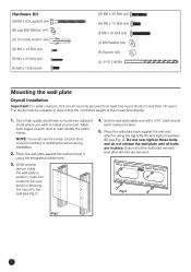
...) (J) M6 Washer (x4) (K) Spacer (x8) (L) 3/16" Drill Bit Mounting the wall plate Drywall Installation Important! Ensure that the wall plate remains level after all bolts are secured. NOTE: You must be capable of supporting the combined weight of each marked location. 5. Place the wall plate back against the wall and level it using the integrated bubble level. 3. Fig.2 Fig.1 2 While another...
...) (J) M6 Washer (x4) (K) Spacer (x8) (L) 3/16" Drill Bit Mounting the wall plate Drywall Installation Important! Ensure that the wall plate remains level after all bolts are secured. NOTE: You must be capable of supporting the combined weight of each marked location. 5. Place the wall plate back against the wall and level it using the integrated bubble level. 3. Fig.2 Fig.1 2 While another...
Installation Manual
Page 3
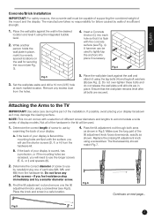
... and lengths to use the shorter screws (D, F, or H) from the hardware kit. 4. English Concrete/Brick Installation IMPORTANT! For safety reasons, the concrete wall must be used . 1. Place the wall plate against the wall and attach it may damage the viewing surface. Insert a Concrete Anchor (C) into place if necessary. A hammer can be capable of supporting the combined weight of the hardware in...
... and lengths to use the shorter screws (D, F, or H) from the hardware kit. 4. English Concrete/Brick Installation IMPORTANT! For safety reasons, the concrete wall must be used . 1. Place the wall plate against the wall and attach it may damage the viewing surface. Insert a Concrete Anchor (C) into place if necessary. A hammer can be capable of supporting the combined weight of the hardware in...
Installation Manual
Page 4
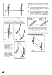
... are using the longer screws on both tilt adjustment rod knobs simultaneously. Fig.11 8. Insert the pin and replace the clip on a display with the mounting holes on back of the rod together and open both arms completely as needed. If you are using the screws identified in Fig.9. 1 2 3 7. Attach the mount arms to the next part...
... are using the longer screws on both tilt adjustment rod knobs simultaneously. Fig.11 8. Insert the pin and replace the clip on a display with the mounting holes on back of the rod together and open both arms completely as needed. If you are using the screws identified in Fig.9. 1 2 3 7. Attach the mount arms to the next part...
Installation Manual
Page 5
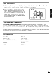
... Display Size: Maximum Load: Universal VESA Mounting Pattern: Tilt Range: Profile: 26" to lock it on the wall plate. Do not release the display until the mount arms have become loose over time. IMPORTANT! Do not release the display until the tilt is locked in place. English Final Installation 1. Fig...display to prevent the display from being lifted from the mount. Inspect all times to unlock the tilt. A padlock can be used at all screws and hardware at the bottom of another person, carefully lift your mount with one hand and rotate one of your display ...
... Display Size: Maximum Load: Universal VESA Mounting Pattern: Tilt Range: Profile: 26" to lock it on the wall plate. Do not release the display until the mount arms have become loose over time. IMPORTANT! Do not release the display until the tilt is locked in place. English Final Installation 1. Fig...display to prevent the display from being lifted from the mount. Inspect all times to unlock the tilt. A padlock can be used at all screws and hardware at the bottom of another person, carefully lift your mount with one hand and rotate one of your display ...