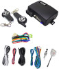
User Guide
Page 1
... Antenna Connection Door Lock Connector Bypass Connector Data Port Connector Tach Learning Page 5 Auto Tach/ Tachless Learning Hybrid Mode Low Idle Learn Wire Description Page 6-7 6-Pin Ignition Connector 2-Pin Park Light & Ground Connector 3-Pin Lock & Unlock Connector 3-Pin Bypass Module Connector 9-Pin Connector Transmitter Programming Page 8 Programming Remote Transmitters Program Mode Page 9 Enter Program Mode Selecting Program Menu Selecting The Programmable Setting Changing The Programmable Setting System Reset Program Menus...
... Antenna Connection Door Lock Connector Bypass Connector Data Port Connector Tach Learning Page 5 Auto Tach/ Tachless Learning Hybrid Mode Low Idle Learn Wire Description Page 6-7 6-Pin Ignition Connector 2-Pin Park Light & Ground Connector 3-Pin Lock & Unlock Connector 3-Pin Bypass Module Connector 9-Pin Connector Transmitter Programming Page 8 Programming Remote Transmitters Program Mode Page 9 Enter Program Mode Selecting Program Menu Selecting The Programmable Setting Changing The Programmable Setting System Reset Program Menus...
User Guide
Page 2
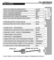
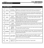
... WHITE/BLUE 5 (+) BRAKE SWITCH INPUT (12VOLT WHEN BRAKE IS PRESSED) PINK 6 (-) HOOD PIN SWITCH INPUT (GROUND WHEN HOOD IS OPENED) GREEN/WHITE 7 (AC) TACH DETECTION INPUT (CONNECT TO COIL, INJECTOR...) BLUE/WHITE 8 (+/-) GLOW PLUG/ WAIT TO START TIMER/ TRIGGER TO START BLUE 9 STATUS LED PROGRAM / VALET BUTTON DO NOT INSTALL THIS SYSTEM INTO A MANUAL TRANSMISSION VEHICLE!! PAGE 3 SYWSIRTEMDIPARGORGARMAMMING...
... WHITE/BLUE 5 (+) BRAKE SWITCH INPUT (12VOLT WHEN BRAKE IS PRESSED) PINK 6 (-) HOOD PIN SWITCH INPUT (GROUND WHEN HOOD IS OPENED) GREEN/WHITE 7 (AC) TACH DETECTION INPUT (CONNECT TO COIL, INJECTOR...) BLUE/WHITE 8 (+/-) GLOW PLUG/ WAIT TO START TIMER/ TRIGGER TO START BLUE 9 STATUS LED PROGRAM / VALET BUTTON DO NOT INSTALL THIS SYSTEM INTO A MANUAL TRANSMISSION VEHICLE!! PAGE 3 SYWSIRTEMDIPARGORGARMAMMING...
User Guide
Page 3
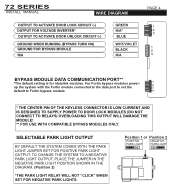
... LIGHT OUTPUT BY DEFAULT THE SYSTEM COMES WITH THE PARK LIGHT JUMPER SET FOR POSITIVE PARK LIGHT OUTPUT. TO CHANGE THE SYSTEM TO A NEGATIVE PARK LIGHT OUTPUT, PLACE THE JUMPER IN THE NEGATIVE PARK LIGHT POSITION SHOWN IN THE DIAGRAM. (Position 2) *THE PARK LIGHT RELAY WILL NOT "CLICK" WHEN SET FOR NEGATIVE PARK LIGHTS. 72 SERIES INSTALL MANUAL PAGE 4 SWYSIRTEEMDIAPGRORAGMRAMMING...
... LIGHT OUTPUT BY DEFAULT THE SYSTEM COMES WITH THE PARK LIGHT JUMPER SET FOR POSITIVE PARK LIGHT OUTPUT. TO CHANGE THE SYSTEM TO A NEGATIVE PARK LIGHT OUTPUT, PLACE THE JUMPER IN THE NEGATIVE PARK LIGHT POSITION SHOWN IN THE DIAGRAM. (Position 2) *THE PARK LIGHT RELAY WILL NOT "CLICK" WHEN SET FOR NEGATIVE PARK LIGHTS. 72 SERIES INSTALL MANUAL PAGE 4 SWYSIRTEEMDIAPGRORAGMRAMMING...
User Guide
Page 4
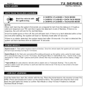
Menu 1 72 SERIES INSTALL MANUAL AUTO TACH/ TACHLESS LEARNING Start the vehicle with the key. Once the starter goes on then off, the unit will learn tach, if there is detected the system will power up the ignition wires, pulse the start until the battery voltage drops. **Hybrid Mode 2 is no starter wire or "Automatic Starting". This option requires a tach connection. Press and release...
Menu 1 72 SERIES INSTALL MANUAL AUTO TACH/ TACHLESS LEARNING Start the vehicle with the key. Once the starter goes on then off, the unit will learn tach, if there is detected the system will power up the ignition wires, pulse the start until the battery voltage drops. **Hybrid Mode 2 is no starter wire or "Automatic Starting". This option requires a tach connection. Press and release...
User Guide
Page 5
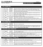
... PIN 1 BLACK PIN 2 WHITE SYSTEM GROUND PARK LIGHT OUTPUT (SELECTABLE) Connect to lock wire from the switch on vehicles with a negative type OUTPUT switch. **LOW CURRENT ONLY** 3 PIN BYPASS MODULE CONNECTOR WHITE/ GROUND WHEN This wire is in the on. 72 SERIES INSTALL MANUAL PAGE 6 SWYSIRTEEMDEPSRCORGIPRTAIOMNMING - PIN 6 BLUE IGNITION OUTPUT This wire will test 0V when key is off, 12volts in...
... PIN 1 BLACK PIN 2 WHITE SYSTEM GROUND PARK LIGHT OUTPUT (SELECTABLE) Connect to lock wire from the switch on vehicles with a negative type OUTPUT switch. **LOW CURRENT ONLY** 3 PIN BYPASS MODULE CONNECTOR WHITE/ GROUND WHEN This wire is in the on. 72 SERIES INSTALL MANUAL PAGE 6 SWYSIRTEEMDEPSRCORGIPRTAIOMNMING - PIN 6 BLUE IGNITION OUTPUT This wire will test 0V when key is off, 12volts in...
User Guide
Page 6
...remote start activation. RELEASE (-) Programmable for a (-) Ignition or (-) Dome Light output with the (#) PROGRAMMABLE button activating car finder mode. INPUT (+) Factory alarm re-arm/ RAP shutdown. PIN 7 GRN/WHITE Connect this wire to the factory horn wire of the vehicle. PIN 9 BLUE GLOW PLUG Default Gas Mode...performed. If ground is used to to the wire at the coil or fuel injector. Programmable. PIN 6 PINK BRAKE SWITCH INPUT (+) This wire must be connected to detect when the vehicle has started. Menu 1 72 SERIES INSTALL MANUAL 9-PIN CONNECTOR PIN 1...
...remote start activation. RELEASE (-) Programmable for a (-) Ignition or (-) Dome Light output with the (#) PROGRAMMABLE button activating car finder mode. INPUT (+) Factory alarm re-arm/ RAP shutdown. PIN 7 GRN/WHITE Connect this wire to the factory horn wire of the vehicle. PIN 9 BLUE GLOW PLUG Default Gas Mode...performed. If ground is used to to the wire at the coil or fuel injector. Programmable. PIN 6 PINK BRAKE SWITCH INPUT (+) This wire must be connected to detect when the vehicle has started. Menu 1 72 SERIES INSTALL MANUAL 9-PIN CONNECTOR PIN 1...
User Guide
Page 7
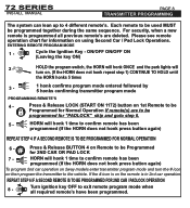
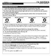
... remote's. Press & Release BUTTON 4 on 1st Remote to be programmed for 2ND CAR OR PAD LOCK 7 - If the # icon is on using Second Car / Pad Lock Operations. Please see remote operation chart for information on the remote is programmed all required remote's have been programmed. ON/OFF ON/OFF ON (Leaving the key ON) 2 - 72 SERIES INSTALL MANUAL PAGE 8 STYRSATNESMMPITRTOEGRRPARMOMGIRNAGM-MMIeNnGu 1 The system can lean up to exit remote program mode when...
... remote's. Press & Release BUTTON 4 on 1st Remote to be programmed for 2ND CAR OR PAD LOCK 7 - If the # icon is on using Second Car / Pad Lock Operations. Please see remote operation chart for information on the remote is programmed all required remote's have been programmed. ON/OFF ON/OFF ON (Leaving the key ON) 2 - 72 SERIES INSTALL MANUAL PAGE 8 STYRSATNESMMPITRTOEGRRPARMOMGIRNAGM-MMIeNnGu 1 The system can lean up to exit remote program mode when...
User Guide
Page 8
... Horn Chirps 3 times. 4 - Press and hold the Program Switch to change the setting. (The horn will honk and the park lights will chip to advance through the settings. *The horn will flash in program menu 3 setting 9. (2 BUTTON REMOTE) SYSTEM RESET 1 - Press and RELEASE the Program Switch 1 time. (Horn will flash to exit. Menu 1 72 SERIES INSTALL MANUAL ENTERING PROGRAM MODE 1 - Press Lock Press Unlock Press Start Press # MENU 1 MENU 2 MENU 3 MENU 4 4 - Turn the ignition key OFF to indicate...
... Horn Chirps 3 times. 4 - Press and hold the Program Switch to change the setting. (The horn will honk and the park lights will chip to advance through the settings. *The horn will flash in program menu 3 setting 9. (2 BUTTON REMOTE) SYSTEM RESET 1 - Press and RELEASE the Program Switch 1 time. (Horn will flash to exit. Menu 1 72 SERIES INSTALL MANUAL ENTERING PROGRAM MODE 1 - Press Lock Press Unlock Press Start Press # MENU 1 MENU 2 MENU 3 MENU 4 4 - Turn the ignition key OFF to indicate...
User Guide
Page 9
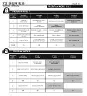
... IGNITION AUTO-LOCKS DISABLED SINGLE LOCK & SINGLE UNLOCK 0.72 SEC PULSES AUX CHANNEL (#) 6-9 NA N/A N/A N/A N/A PROGRAM MODE 2 SETTING # LED FLASHES SETTING DESCRIPTION OPTION 1 1 CHIRP 1 VALET SETTINGS SECURE VALET 15 SECONDS OPTION 2 2 CHIRPS STANDARD VALET 5 SECONDS 2 PARK LIGHT OUTPUT 30 SECONDS ON DISARM NORMAL OPERATION OPTION 3 3 CHIRPS 3 HORN TIMING 5MS PULSED OUTPUT 50MS PULSED OUTPUT 10MS PULSED OUTPUT 4 N/A N/A N/A N/A 5 HOOD PIN TYPE N/C FACTORY TYPE...
... IGNITION AUTO-LOCKS DISABLED SINGLE LOCK & SINGLE UNLOCK 0.72 SEC PULSES AUX CHANNEL (#) 6-9 NA N/A N/A N/A N/A PROGRAM MODE 2 SETTING # LED FLASHES SETTING DESCRIPTION OPTION 1 1 CHIRP 1 VALET SETTINGS SECURE VALET 15 SECONDS OPTION 2 2 CHIRPS STANDARD VALET 5 SECONDS 2 PARK LIGHT OUTPUT 30 SECONDS ON DISARM NORMAL OPERATION OPTION 3 3 CHIRPS 3 HORN TIMING 5MS PULSED OUTPUT 50MS PULSED OUTPUT 10MS PULSED OUTPUT 4 N/A N/A N/A N/A 5 HOOD PIN TYPE N/C FACTORY TYPE...
User Guide
Page 10
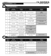
... SETTINGS DELAY 5 BYPASS MODULE FORTIN BYPASS IDATA LINK BYPASS *IF THE STARTER IS POWERED UP WITH A FORTIN BYPASS UNIT IT WILL AUTO SET FOR FORTIN. Menu 1 72 SERIES INSTALL MANUAL PROGRAM MODE 3 SETTING # LED FLASHES 1 SETTING ...BUTTON UNLOCK ONLY 9 1 / 2 BUTTON UNLOCK AND START FOR REMOTE ONLY TIMER MODE & MENU 4 PROGRAM MODE 4 NORMAL DISARM UNLOCK / LOCK TOGGLE UNLOCK AND START FOR TIMER MODE & MENU 4 UNLOCK OUTPUT SETTING # LED FLASHES SETTING DESCRIPTION 1 TACH OPTIONS OPTION 1 1 CHIRP HYBRID MODE 1 OPTION 2 2 CHIRPS HYBRID MODE TWO OPTION 3 3 CHIRPS AUTO...
... SETTINGS DELAY 5 BYPASS MODULE FORTIN BYPASS IDATA LINK BYPASS *IF THE STARTER IS POWERED UP WITH A FORTIN BYPASS UNIT IT WILL AUTO SET FOR FORTIN. Menu 1 72 SERIES INSTALL MANUAL PROGRAM MODE 3 SETTING # LED FLASHES 1 SETTING ...BUTTON UNLOCK ONLY 9 1 / 2 BUTTON UNLOCK AND START FOR REMOTE ONLY TIMER MODE & MENU 4 PROGRAM MODE 4 NORMAL DISARM UNLOCK / LOCK TOGGLE UNLOCK AND START FOR TIMER MODE & MENU 4 UNLOCK OUTPUT SETTING # LED FLASHES SETTING DESCRIPTION 1 TACH OPTIONS OPTION 1 1 CHIRP HYBRID MODE 1 OPTION 2 2 CHIRPS HYBRID MODE TWO OPTION 3 3 CHIRPS AUTO...
User Guide
Page 11
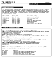
... "ON" Solid Series of 4 Flashes Series of 5 Flashes Series of 5 Flashes Series of 6 Flashes Series of 7 Flashes Series of times as normal. Press the Program Button again for the second code. ***The HORN will honk the same number of 8 Flashes DIAGNOSTIC CODE System Is In Service Mode Not in memory. The system made 3 start button is in Service Mode, simply follow the instructions listed in memory, the system will not record any further...
... "ON" Solid Series of 4 Flashes Series of 5 Flashes Series of 5 Flashes Series of 6 Flashes Series of 7 Flashes Series of times as normal. Press the Program Button again for the second code. ***The HORN will honk the same number of 8 Flashes DIAGNOSTIC CODE System Is In Service Mode Not in memory. The system made 3 start button is in Service Mode, simply follow the instructions listed in memory, the system will not record any further...
User Guide
Page 12
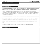
.... INSTALLER NOTES PRESS AND RELEASE UNLOCK AND START TO CANCEL TIMER MODE ONCE SET. *ONE HOUR TIMER MODE IS NOT AVAILABLE WITH 2 BUTTON REMOTE'S. PRESS UNLOCK TO SET 2 HOUR, START WILL SET THREE HOUR AND UNLOCK AND START TOGETHER WILL SET THE FOUR TIMER. Menu 1 72 SERIES INSTALL MANUAL 2 BUTTON REMOTE WHEN PROGRAMMED FOR 2 BUTTON OR LOCK/UNLOCK TOGGLE PRESSING UNLOCK AND START AT THE SAME TIME WILL SELECT MENU 4 WHILE IN PROGRAM MODE.
.... INSTALLER NOTES PRESS AND RELEASE UNLOCK AND START TO CANCEL TIMER MODE ONCE SET. *ONE HOUR TIMER MODE IS NOT AVAILABLE WITH 2 BUTTON REMOTE'S. PRESS UNLOCK TO SET 2 HOUR, START WILL SET THREE HOUR AND UNLOCK AND START TOGETHER WILL SET THE FOUR TIMER. Menu 1 72 SERIES INSTALL MANUAL 2 BUTTON REMOTE WHEN PROGRAMMED FOR 2 BUTTON OR LOCK/UNLOCK TOGGLE PRESSING UNLOCK AND START AT THE SAME TIME WILL SELECT MENU 4 WHILE IN PROGRAM MODE.
User Guide
Page 13
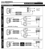
72 SERIES INSTALL MANUAL DOOR LOCK DIAGRAMS Door lock Output PAGE 14 SYRSETLEAMY DPIRAOGGRRAAMMSMING - Menu 1 Vehicle's Lock/Unlock Switch To Control Relay or Actuators Alarm and / or Starter Module NEGATIVE DOOR LOCK (LOW CURRENT) Green Blue Alarm and / or Starter Module NEGATIVE DOOR LOCK (LOW CURRENT) Door lock Output Green Blue USE SPDT 12v Relay 87 87a 86 85 30 87...
72 SERIES INSTALL MANUAL DOOR LOCK DIAGRAMS Door lock Output PAGE 14 SYRSETLEAMY DPIRAOGGRRAAMMSMING - Menu 1 Vehicle's Lock/Unlock Switch To Control Relay or Actuators Alarm and / or Starter Module NEGATIVE DOOR LOCK (LOW CURRENT) Green Blue Alarm and / or Starter Module NEGATIVE DOOR LOCK (LOW CURRENT) Door lock Output Green Blue USE SPDT 12v Relay 87 87a 86 85 30 87...
User Guide
Page 14
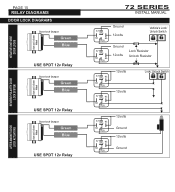
... REVERSE POLARITY DOOR LOCK SYSTEM Alarm and / or Starter Module NEGATIVE ONE WIRE DOOR LOCKS Alarm and / or Starter Module PAGE 15 SYRSETLEAMY DPIRAOGGRRAAMMSMING - Menu 1 DOOR LOCK DIAGRAMS Door lock Output Green Blue USE SPDT 12v Relay Door lock Output Green Blue USE SPDT 12v Relay Door lock Output Green Blue USE SPDT 12v Relay 72 SERIES INSTALL MANUAL 87 87a 86...
... REVERSE POLARITY DOOR LOCK SYSTEM Alarm and / or Starter Module NEGATIVE ONE WIRE DOOR LOCKS Alarm and / or Starter Module PAGE 15 SYRSETLEAMY DPIRAOGGRRAAMMSMING - Menu 1 DOOR LOCK DIAGRAMS Door lock Output Green Blue USE SPDT 12v Relay Door lock Output Green Blue USE SPDT 12v Relay Door lock Output Green Blue USE SPDT 12v Relay 72 SERIES INSTALL MANUAL 87 87a 86...


