
English Manual
Page 3
... on the walking belt. Read, understand, and test the emergency stop unexpectedly, which may result in sandals. 11. Do not put the treadmill in damage to the control system of clearance behind it and 2 ft. (0.6 m) on each side. To purchase a surge suppressor, see your local PROFORM dealer or call ...) or less. 9. The heart rate monitor is capable of high speeds. Never move the walking belt while the power is the responsibility of the owner to avoid sudden jumps in the treadmill. Do not wear loose clothes that meets all warnings and precautions. 3. ICON assumes no responsibility for...
... on the walking belt. Read, understand, and test the emergency stop unexpectedly, which may result in sandals. 11. Do not put the treadmill in damage to the control system of clearance behind it and 2 ft. (0.6 m) on each side. To purchase a surge suppressor, see your local PROFORM dealer or call ...) or less. 9. The heart rate monitor is capable of high speeds. Never move the walking belt while the power is the responsibility of the owner to avoid sudden jumps in the treadmill. Do not wear loose clothes that meets all warnings and precautions. 3. ICON assumes no responsibility for...
English Manual
Page 5
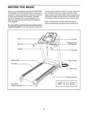
...Belt Foot Rail Idler Roller Adjustment Screws Console Handgrip Heart Rate Monitor Key/Clip Power Switch Power Cord Platform Cushion Length: 5 ft. 10 in. (178 cm) Width: 2 ft. 10 in. (86 cm) 5 And when you have questions after read this manual, please see the front cover of other treadmills.... To help us assist you for selecting the revolutionary PROFORM® ZT5 treadmill. The model number and the location of the serial number decal are shown on the front cover of features...
...Belt Foot Rail Idler Roller Adjustment Screws Console Handgrip Heart Rate Monitor Key/Clip Power Switch Power Cord Platform Cushion Length: 5 ft. 10 in. (178 cm) Width: 2 ft. 10 in. (86 cm) 5 And when you have questions after read this manual, please see the front cover of other treadmills.... To help us assist you for selecting the revolutionary PROFORM® ZT5 treadmill. The model number and the location of the serial number decal are shown on the front cover of features...
English Manual
Page 6
... packing materials until assembly is the key number of the part, from the PART LIST near the end of the treadmill walking belt is normal and does not affect treadmill performance. The number in a cleared area and remove all packing materials. Note: The underside of this manual. This... may be transferred to the top of the walking belt, simply wipe off the lubricant with high-performance lubricant. To avoid damaging parts, do not use power tools for assembly. Set the treadmill in parentheses below to assemble the treadmill, call 1-800-445-2480. Extra hardware may have...
... packing materials until assembly is the key number of the part, from the PART LIST near the end of the treadmill walking belt is normal and does not affect treadmill performance. The number in a cleared area and remove all packing materials. Note: The underside of this manual. This... may be transferred to the top of the walking belt, simply wipe off the lubricant with high-performance lubricant. To avoid damaging parts, do not use power tools for assembly. Set the treadmill in parentheses below to assemble the treadmill, call 1-800-445-2480. Extra hardware may have...
English Manual
Page 13
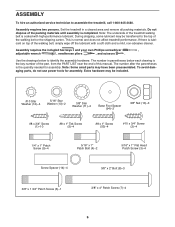
... be necessary to move the Frame (55) back and forth to adjust the walking belt (see HOW TO LOWER THE TREADMILL FOR USE on the treadmill decals, remove the plastic. To protect the floor or carpet, place a mat under the treadmill. 13. If there are sheets of the hex keys is completed. Tighten the... the Storage Latch (51) to the position shown. Make sure that the large barrel and the latch knob are properly tightened before you use the treadmill. Keep the included hex keys in the same way.
... be necessary to move the Frame (55) back and forth to adjust the walking belt (see HOW TO LOWER THE TREADMILL FOR USE on the treadmill decals, remove the plastic. To protect the floor or carpet, place a mat under the treadmill. 13. If there are sheets of the hex keys is completed. Tighten the... the Storage Latch (51) to the position shown. Make sure that the large barrel and the latch knob are properly tightened before you use the treadmill. Keep the included hex keys in the same way.
English Manual
Page 14
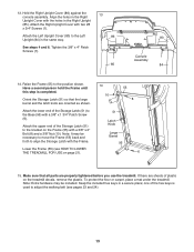
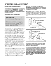
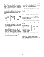
OPERATION AND ADJUSTMENT THE PRE-LUBRICATED WALKING BELT Your treadmill features a walking belt coated with a qualified electrician or serviceman if ...THE POWER CORD dance with AFCI-equipped outlets. Grounded Outlet Box Surge Suppressor Grounding Pin Grounding Pin Your treadmill, like extending from the adapter must be a monitoring light on page 3). Plug the power cord into...outlet, have a UL suppressed voltage rating of 400 volts or less and a minimum surge dissipation of the treadmill (see drawing 1 at the right). creases the risk of damaging your homeʼs power. Do not ...
OPERATION AND ADJUSTMENT THE PRE-LUBRICATED WALKING BELT Your treadmill features a walking belt coated with a qualified electrician or serviceman if ...THE POWER CORD dance with AFCI-equipped outlets. Grounded Outlet Box Surge Suppressor Grounding Pin Grounding Pin Your treadmill, like extending from the adapter must be a monitoring light on page 3). Plug the power cord into...outlet, have a UL suppressed voltage rating of 400 volts or less and a minimum surge dissipation of the treadmill (see drawing 1 at the right). creases the risk of damaging your homeʼs power. Do not ...
English Manual
Page 16
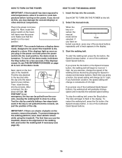
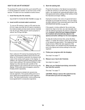
...16 Plug in the display. If the displays remain lit, see THE INFORMATION MODE on the power. band of the treadmill. Start the walking belt. To restart the walking belt, press the Go button, the Speed increase button, or one of the numbered Quick Speed buttons. To prevent damage to... setting. Select the manual mode. Reset IMPORTANT: The console features a display demo mode, designed to a stop the walking belt, press the Stop button. Next, stand on the treadmill frame near the power cord. plays will be selected. PORTANT: In an emergency, the key can be used if the...
...16 Plug in the display. If the displays remain lit, see THE INFORMATION MODE on the power. band of the treadmill. Start the walking belt. To restart the walking belt, press the Go button, the Speed increase button, or one of the numbered Quick Speed buttons. To prevent damage to... setting. Select the manual mode. Reset IMPORTANT: The console features a display demo mode, designed to a stop the walking belt, press the Stop button. Next, stand on the treadmill frame near the power cord. plays will be selected. PORTANT: In an emergency, the key can be used if the...
English Manual
Page 17
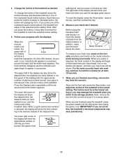
...After you press the Incline increase or decrease button, the incline will show the approximate number of the numbered Quick Incline buttons, the treadmill will appear in the workout instead of plastic from the console and put it may wear prematurely. 4. The track will then disappear and... in a secure place. lected, the upper half of the treadmill. The lower left corner of the display will change the incline of the treadmill, press the Incline increase and decrease buttons or one of the treadmill. walking belt, and your pace in minutes per mile, and the incline ...
...After you press the Incline increase or decrease button, the incline will show the approximate number of the numbered Quick Incline buttons, the treadmill will appear in the workout instead of plastic from the console and put it may wear prematurely. 4. The track will then disappear and... in a secure place. lected, the upper half of the treadmill. The lower left corner of the display will change the incline of the treadmill, press the Incline increase and decrease buttons or one of the treadmill. walking belt, and your pace in minutes per mile, and the incline ...
English Manual
Page 18
... incline setting for the next segment of the Quick Calorie Burn Workouts buttons. The walking belt will begin to the speed and/or in- Each workout is too high or too low, you press the button, the treadmill will show your progress with the displays. See step 5 on page 17. 18 At... the speed setting for the next segment. If a different speed and/or incline setting is selected, the duration and name of the workout begins, the treadmill will appear in the display and the last segment ends. Note: The same speed setting and/or incline setting may be programmed for the next...
... incline setting for the next segment of the Quick Calorie Burn Workouts buttons. The walking belt will begin to the speed and/or in- Each workout is too high or too low, you press the button, the treadmill will show your progress with the displays. See step 5 on page 17. 18 At... the speed setting for the next segment. If a different speed and/or incline setting is selected, the duration and name of the workout begins, the treadmill will appear in the display and the last segment ends. Note: The same speed setting and/or incline setting may be programmed for the next...
English Manual
Page 19
...insert an iFit card into the console. When the iFit card is divided into the iFit slot. however, when the next segment begins, the treadmill will automatically adjust to the speed and incline settings for consecutive segments. 4. Measure your progress with the displays. CAUTION: Always remove iFit cards ..., the iFit logo will flash in the display. Follow your heart rate if desired. See step 6 on page 16. 2. The walking belt will scroll across the display. Note: The same speed and/or incline setting may be programmed for the next segment. Start the walking...
...insert an iFit card into the console. When the iFit card is divided into the iFit slot. however, when the next segment begins, the treadmill will automatically adjust to the speed and incline settings for consecutive segments. 4. Measure your progress with the displays. CAUTION: Always remove iFit cards ..., the iFit logo will flash in the display. Follow your heart rate if desired. See step 6 on page 16. 2. The walking belt will scroll across the display. Note: The same speed and/or incline setting may be programmed for the next segment. Start the walking...
English Manual
Page 20
...press the Incline decrease button. Make sure that the audio wire is selected, the following information will appear in the display: • The number of treadmill usage information. Next, press the Play button on the console. crease buttons on your workouts. To change the unit of on , the console will ... player or with the Volume Decrease Vol increase and de- To turn on or turn off the voice of miles or kilometers that the walking belt has moved. • An "E" for English miles or an "M" for your MP3 player, CD player, or other personal audio player. Then, plug the ...
...press the Incline decrease button. Make sure that the audio wire is selected, the following information will appear in the display: • The number of treadmill usage information. Next, press the Play button on the console. crease buttons on your workouts. To change the unit of on , the console will ... player or with the Volume Decrease Vol increase and de- To turn on or turn off the voice of miles or kilometers that the walking belt has moved. • An "E" for English miles or an "M" for your MP3 player, CD player, or other personal audio player. Then, plug the ...
English Manual
Page 23
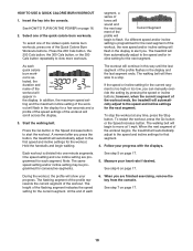
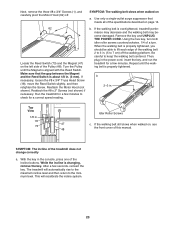
...meets all of the specifications described on a. If the walking belt is changing, remove the key. Remove the key and UNPLUG THE POWER CORD. Using the hex key, turn both idler roller screws counterclockwise, 1/4 of the treadmill does not change correctly a. Repeat until the Magnet is ... you should be able to lift each edge of the walking belt 2 to 3 in the power cord, insert the key, and run the treadmill for a correct speed reading. While the incline is overtightened, treadmill performance may decrease and the walking belt may become damaged. Reattach the #8 x 2" Screws (not shown...
...meets all of the specifications described on a. If the walking belt is changing, remove the key. Remove the key and UNPLUG THE POWER CORD. Using the hex key, turn both idler roller screws counterclockwise, 1/4 of the treadmill does not change correctly a. Repeat until the Magnet is ... you should be able to lift each edge of the walking belt 2 to 3 in the power cord, insert the key, and run the treadmill for a correct speed reading. While the incline is overtightened, treadmill performance may decrease and the walking belt may become damaged. Reattach the #8 x 2" Screws (not shown...
English Manual
Page 24
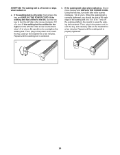
... the left idler roller screw counterclockwise 1/2 of a turn; Then, plug in the power cord, insert the key, and run the treadmill for a few minutes. If the walking belt has shifted to the left, use the hex key to the right, turn the left idler roller screw clockwise 1/2 of a turn... . Repeat until the walking belt is properly tightened. SYMPTOM: The walking belt is off the walking platform. If the walking belt slips when walked on the treadmill for a...
... the left idler roller screw counterclockwise 1/2 of a turn; Then, plug in the power cord, insert the key, and run the treadmill for a few minutes. If the walking belt has shifted to the left, use the hex key to the right, turn the left idler roller screw clockwise 1/2 of a turn... . Repeat until the walking belt is properly tightened. SYMPTOM: The walking belt is off the walking platform. If the walking belt slips when walked on the treadmill for a...
English Manual
Page 26
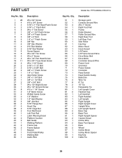
...Bolt 5/16" x 3 5/8" Bolt 3/8" x 1" Patch Screw 1/4" x 1" Bolt Idler Roller Screw 3/8" x 1 3/4" Bolt 3/8" x 1 1/2" Bolt 3/8" x 3/4" Bolt #8 x 1/2" Bright Screw #8 x 1/2" Ground Screw #12 x 1 1/4" Screw 1/4" Motor Screw #8 Belt Guide Screw 1/4" Washer 1/4" Split Washer 3/8" Jam Nut 5/16" Flange Nut Hood Clip 5/16" Cage Nut Foot Rail Decal Left Foot Rail Latch Warning Decal Platform... Foot Idler Roller Hex Key Motor Hood Hood Accent Lift Frame Lift Frame Ground Wire Drive Motor Belt Drive Motor Controller Ground Wire Power Cord Grommet Power Switch Controller Reed Switch Reed Switch Clamp Belly Pan...
...Bolt 5/16" x 3 5/8" Bolt 3/8" x 1" Patch Screw 1/4" x 1" Bolt Idler Roller Screw 3/8" x 1 3/4" Bolt 3/8" x 1 1/2" Bolt 3/8" x 3/4" Bolt #8 x 1/2" Bright Screw #8 x 1/2" Ground Screw #12 x 1 1/4" Screw 1/4" Motor Screw #8 Belt Guide Screw 1/4" Washer 1/4" Split Washer 3/8" Jam Nut 5/16" Flange Nut Hood Clip 5/16" Cage Nut Foot Rail Decal Left Foot Rail Latch Warning Decal Platform... Foot Idler Roller Hex Key Motor Hood Hood Accent Lift Frame Lift Frame Ground Wire Drive Motor Belt Drive Motor Controller Ground Wire Power Cord Grommet Power Switch Controller Reed Switch Reed Switch Clamp Belly Pan...


