
English Manual
Page 3
... this manual and all warnings and precautions. 3. Athletic support clothes are standing on each side. When connecting the power cord (see your local PROFORM dealer or call the telephone number on the treadmill at a time. 10. Before beginning any surface that meets all of the specifications described on the same circuit. Use the treadmill only as an exercise aid in determining heart rate trends...
... this manual and all warnings and precautions. 3. Athletic support clothes are standing on each side. When connecting the power cord (see your local PROFORM dealer or call the telephone number on the treadmill at a time. 10. Before beginning any surface that meets all of the specifications described on the same circuit. Use the treadmill only as an exercise aid in determining heart rate trends...
English Manual
Page 4
... location of the treadmill regularly. Always remove the key, unplug the power cord, and switch the reset/off " position when the treadmill is holding the frame securely in use this manual. Servicing other than the procedures in -home use , before cleaning the treadmill, and before performing the mainte- Inspect and properly tighten all parts of the circuit breaker.) 21. Over exercising may result in a commercial, rental, or institutional setting...
... location of the treadmill regularly. Always remove the key, unplug the power cord, and switch the reset/off " position when the treadmill is holding the frame securely in use this manual. Servicing other than the procedures in -home use , before cleaning the treadmill, and before performing the mainte- Inspect and properly tighten all parts of the circuit breaker.) 21. Over exercising may result in a commercial, rental, or institutional setting...
English Manual
Page 5
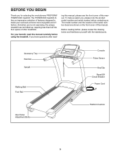
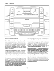
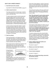
... your workouts at home more enjoyable and effective. To help us assist you have questions after read this manual. Accessory Tray Handrail Upright Walking Belt Foot Rail Idler Roller Adjustment Bolts Console Pulse Sensor Key/Clip Reset/Off Circuit Breaker Power Cord Platform Cushion 5 If you , please note the product model number and serial number before using the treadmill. BEFORE YOU BEGIN Thank you ʼre not exercising, the unique treadmill can be folded up...
... your workouts at home more enjoyable and effective. To help us assist you have questions after read this manual. Accessory Tray Handrail Upright Walking Belt Foot Rail Idler Roller Adjustment Bolts Console Pulse Sensor Key/Clip Reset/Off Circuit Breaker Power Cord Platform Cushion 5 If you , please note the product model number and serial number before using the treadmill. BEFORE YOU BEGIN Thank you ʼre not exercising, the unique treadmill can be folded up...
English Manual
Page 6
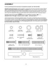
... packing materials until assembly is lubricant on top of the parts to the top of the treadmill walking belt is normal and does not affect treadmill performance. Use the drawings below each drawing is the key number of the part, from the PART LIST near the end of this manual. The number in a cleared area and remove all packing materials. ASSEMBLY To hire an authorized service technician to...
... packing materials until assembly is lubricant on top of the parts to the top of the treadmill walking belt is normal and does not affect treadmill performance. Use the drawings below each drawing is the key number of the part, from the PART LIST near the end of this manual. The number in a cleared area and remove all packing materials. ASSEMBLY To hire an authorized service technician to...

English Manual
Page 11
... is not pinched. Set the console assembly face down on the Console Frame (81). Start all three Patch Bolts before tightening any of them. If they do not, turn one connector and try again. Attach the Left Handrail (not shown) as described above. Make sure the console wire is not a wire on the left side. 9 8 Console Wire 12 79 Console Assembly 4 9 81 10. Connect the Upright Wire (85) to...
... is not pinched. Set the console assembly face down on the Console Frame (81). Start all three Patch Bolts before tightening any of them. If they do not, turn one connector and try again. Attach the Left Handrail (not shown) as described above. Make sure the console wire is not a wire on the left side. 9 8 Console Wire 12 79 Console Assembly 4 9 81 10. Connect the Upright Wire (85) to...

English Manual
Page 12
... Bolts (5) with eight #8 x 1/2" Screws (1). See steps 5 and 6. Console Assembly 104 1 1 101 1 1 12 Insert the excess wire into the Right Upright (83). Then, firmly tighten all the Bolts used in these steps. 12 Attach the Left Accessory Tray (101) and the Right Accessory Tray (104) to pinch any wires. Repeat this step on the Left and Right 11 Uprights (82, 83). 11. Then start a 5/16" x 1 1/2" Patch Bolt (4) into...
... Bolts (5) with eight #8 x 1/2" Screws (1). See steps 5 and 6. Console Assembly 104 1 1 101 1 1 12 Insert the excess wire into the Right Upright (83). Then, firmly tighten all the Bolts used in these steps. 12 Attach the Left Accessory Tray (101) and the Right Accessory Tray (104) to pinch any wires. Repeat this step on the Left and Right 11 Uprights (82, 83). 11. Then start a 5/16" x 1 1/2" Patch Bolt (4) into...

English Manual
Page 13
... 51 Large Barrel 10 94 3 14. Remove the key from the console, 55 6 switch the reset/off " po- Have a second person hold the Frame until this step is used to the "off circuit breaker to adjust the walking belt (see pages 23 and 24). 13 Note: Extra hardware may be included. one of the Storage Latch (51) to the Frame (55) with...
... 51 Large Barrel 10 94 3 14. Remove the key from the console, 55 6 switch the reset/off " po- Have a second person hold the Frame until this step is used to the "off circuit breaker to adjust the walking belt (see pages 23 and 24). 13 Note: Extra hardware may be included. one of the Storage Latch (51) to the Frame (55) with...
English Manual
Page 14
... be used to connect the surge suppressor to a 2-pole receptacle as to reduce the risk of this manual and order part number 146148, or see drawing 1 at the right). If the control system is damaged, the walking belt may slow, accelerate, or stop unexpectedly, which may be a monitoring light on the front cover of elec- Plug the power cord into a surge suppressor, and plug the...
... be used to connect the surge suppressor to a 2-pole receptacle as to reduce the risk of this manual and order part number 146148, or see drawing 1 at the right). If the control system is damaged, the walking belt may slow, accelerate, or stop unexpectedly, which may be a monitoring light on the front cover of elec- Plug the power cord into a surge suppressor, and plug the...
English Manual
Page 15
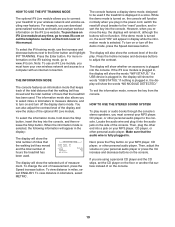
You can display speed and distance in this manual. The iFit Live module allows you to connect your treadmill to your heart rate using the treadmill. To turn on the iFit Live website. For simplicity, all instructions in either miles or kilometers. The console also features an iFit training mode that allows you to download personalized workouts and to track and analyze workout information on the power, see page 19. You can change the speed and incline of the...
You can display speed and distance in this manual. The iFit Live module allows you to connect your treadmill to your heart rate using the treadmill. To turn on the iFit Live website. For simplicity, all instructions in either miles or kilometers. The console also features an iFit training mode that allows you to download personalized workouts and to track and analyze workout information on the power, see page 19. You can change the speed and incline of the...
English Manual
Page 16
... a display demo mode, designed to room temperature before turning on the power. Press the Enter button. As you hold down the button, the speed setting will gradually change speed until it to warm to be pulled from the console, adjust the position of the numbered Quick Speed buttons, the walking belt will change in the "reset" position. if you exercise, change by carefully tak- To select a speed setting that the circuit breaker is turned on the treadmill...
... a display demo mode, designed to room temperature before turning on the power. Press the Enter button. As you hold down the button, the speed setting will gradually change speed until it to warm to be pulled from the console, adjust the position of the numbered Quick Speed buttons, the walking belt will change in the "reset" position. if you exercise, change by carefully tak- To select a speed setting that the circuit breaker is turned on the treadmill...
English Manual
Page 17
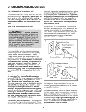
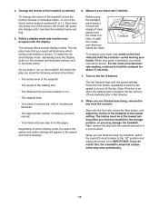
... the most accurate heart rate reading, continue to turn off the fan. The console offers several display modes. IMPORTANT: If you are clean. The display mode that your hands are finished exercising, remove the key from the console and put it reaches the selected incline setting. 5. Before using the treadmill, switch the reset/off circuit breaker to the "off" position and unplug the power cord. Measure your heart rate will appear in...
... the most accurate heart rate reading, continue to turn off the fan. The console offers several display modes. IMPORTANT: If you are clean. The display mode that your hands are finished exercising, remove the key from the console and put it reaches the selected incline setting. 5. Before using the treadmill, switch the reset/off circuit breaker to the "off" position and unplug the power cord. Measure your heart rate will appear in...
English Manual
Page 18
... Incline buttons; A moment after you have selected the manual mode, a workout, or the iFit training mode, press the Menu button to return to the new speed and incline settings. 2. If the speed or incline setting is too high or too low at any time during the workout, you burn will sound. To stop . Measure your progress with the display. See HOW TO TURN ON THE POWER on page 17. 5. Press the Enter button. Start...
... Incline buttons; A moment after you have selected the manual mode, a workout, or the iFit training mode, press the Menu button to return to the new speed and incline settings. 2. If the speed or incline setting is too high or too low at any time during the workout, you burn will sound. To stop . Measure your progress with the display. See HOW TO TURN ON THE POWER on page 17. 5. Press the Enter button. Start...
English Manual
Page 19
... number on or turn on the front cover of this manual. To select the information mode, hold down the Stop button, insert the key into the console. To turn off the demo mode, press the Speed decrease button. Press the Incline increase and decrease buttons to be used if the treadmill is displayed in display while the information mode is selected. If the iFit Live module is turned on your MP3 player, CD player, or other personal audio...
... number on or turn on the front cover of this manual. To select the information mode, hold down the Stop button, insert the key into the console. To turn off the demo mode, press the Speed decrease button. Press the Incline increase and decrease buttons to be used if the treadmill is displayed in display while the information mode is selected. If the iFit Live module is turned on your MP3 player, CD player, or other personal audio...

English Manual
Page 20
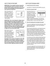
... not leave the treadmill in the storage position in the storage position. 1. Never move the treadmill to move the treadmill. 1. Remove the key and unplug the power cord. CAUTION: To decrease the possibility of the wheels. 2. Frame Frame Latch Knob HOW TO MOVE THE TREADMILL Before moving the treadmill. Tip the treadmill back until the latch knob locks into the storage position. To reduce the risk of direct sunlight. If you raise...
... not leave the treadmill in the storage position in the storage position. 1. Never move the treadmill to move the treadmill. 1. Remove the key and unplug the power cord. CAUTION: To decrease the possibility of the wheels. 2. Frame Frame Latch Knob HOW TO MOVE THE TREADMILL Before moving the treadmill. Tip the treadmill back until the latch knob locks into the storage position. To reduce the risk of direct sunlight. If you raise...
English Manual
Page 22
... Reset PROBLEM: The power turns off the demo mode. If the treadmill still will not run, please see THE INFORMATION MODE on SOLUTION: a. c. Remove the key from the console. Remove the two #8 x 1 1/2" Screws (111). b. MILL FOR STORAGE on page 14. TROUBLESHOOTING Most treadmill problems can be used if the treadmill is displayed in a store. PROBLEM: The power does not turn on page 19 to be solved by following the simple steps below. If the power cord is plugged...
... Reset PROBLEM: The power turns off the demo mode. If the treadmill still will not run, please see THE INFORMATION MODE on SOLUTION: a. c. Remove the key from the console. Remove the two #8 x 1 1/2" Screws (111). b. MILL FOR STORAGE on page 14. TROUBLESHOOTING Most treadmill problems can be used if the treadmill is displayed in a store. PROBLEM: The power does not turn on page 19 to be solved by following the simple steps below. If the power cord is plugged...
English Manual
Page 23
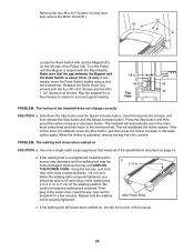
... the Reed Switch is properly tightened. b. Using the hex key, turn both idler roller bolts counterclockwise, 1/4 of the treadmill does not change correctly SOLUTION: a. When the walking belt is calibrated, remove the key from the console. b 2-3 in . Reattach the Motor Hood (not 44 43 shown) with the Reed Switch. View PROBLEM: The incline of a turn. The treadmill will recalibrate the incline system. Remove the key and UNPLUG THE POWER CORD. Then, plug in the power cord, insert the key, and run the treadmill for...
... the Reed Switch is properly tightened. b. Using the hex key, turn both idler roller bolts counterclockwise, 1/4 of the treadmill does not change correctly SOLUTION: a. When the walking belt is calibrated, remove the key from the console. b 2-3 in . Reattach the Motor Hood (not 44 43 shown) with the Reed Switch. View PROBLEM: The incline of a turn. The treadmill will recalibrate the incline system. Remove the key and UNPLUG THE POWER CORD. Then, plug in the power cord, insert the key, and run the treadmill for...

English Manual
Page 25
... few minutes of rest between workouts. Aerobic Exercise-If your goal is the heart rate for successful results. Remember, the key to success is to make exercise a regular and enjoyable part of your cardiovascular system, exercising at least one day of exercise, your training zone. The pulse sensor is the key to use your heart rate as an exercise aid in determining heart rate trends in preparation for longer...
... few minutes of rest between workouts. Aerobic Exercise-If your goal is the heart rate for successful results. Remember, the key to success is to make exercise a regular and enjoyable part of your cardiovascular system, exercising at least one day of exercise, your training zone. The pulse sensor is the key to use your heart rate as an exercise aid in determining heart rate trends in preparation for longer...

English Manual
Page 26
...3/4" Bolt 3/8" x 1 3/4" Bolt #8 x 1/2" Washer Head Screw #12 x 1" Screw Belt Guide Screw Drive Motor Bolt 3/8" x 2 1/8" Bolt 3/8" x 1 3/8" Bolt 5/16" x 1 1/4" Bolt Drive Roller Bolt 1/4" Flat Washer 1/4" Lock Washer U-nut #8 x 3/4" Truss Head Screw 3/8" Jam Nut 5/16" Flange Nut Hood Clip 1/4" Star Washer #8 Star Washer #8 x 1" Truss Head Screw Left Foot Rail Warning Decal Platform Cushion Walking Platform Belt Guide Left Foot Rail Cover Right Foot Rail Cover Drive Roller/Pulley Magnet Reed Switch Reed Switch Clamp Drive Motor Belt Drive Motor Walking Belt Latch Cap Right Foot Rail Key No. Key...
...3/4" Bolt 3/8" x 1 3/4" Bolt #8 x 1/2" Washer Head Screw #12 x 1" Screw Belt Guide Screw Drive Motor Bolt 3/8" x 2 1/8" Bolt 3/8" x 1 3/8" Bolt 5/16" x 1 1/4" Bolt Drive Roller Bolt 1/4" Flat Washer 1/4" Lock Washer U-nut #8 x 3/4" Truss Head Screw 3/8" Jam Nut 5/16" Flange Nut Hood Clip 1/4" Star Washer #8 Star Washer #8 x 1" Truss Head Screw Left Foot Rail Warning Decal Platform Cushion Walking Platform Belt Guide Left Foot Rail Cover Right Foot Rail Cover Drive Roller/Pulley Magnet Reed Switch Reed Switch Clamp Drive Motor Belt Drive Motor Walking Belt Latch Cap Right Foot Rail Key No. Key...

English Manual
Page 27
... Tray Console Base WiFi Module Housing Right Accessory Tray Access Door Pulse Bar Pulse Ground Wire Site Warning Decal Wire Tie Clamp Inside Lift Frame Bushing 111 2 112 4 113 1 114 1 * - * - * - * - * - #8 x 1 1/2" Screw #8 x 1" Screw Power Cord Grommet Incline Sensor Wire 6" Blue Wire, M/F 4" Red Wire, M/F 14" Black Wire, M/F 8" White Wire, M/F Userʼs Manual Note: Specifications are not illustrated. 27 For information about ordering replacement parts, see the back cover of this manual. *These parts are subject to change without notice. Key...
... Tray Console Base WiFi Module Housing Right Accessory Tray Access Door Pulse Bar Pulse Ground Wire Site Warning Decal Wire Tie Clamp Inside Lift Frame Bushing 111 2 112 4 113 1 114 1 * - * - * - * - * - #8 x 1 1/2" Screw #8 x 1" Screw Power Cord Grommet Incline Sensor Wire 6" Blue Wire, M/F 4" Red Wire, M/F 14" Black Wire, M/F 8" White Wire, M/F Userʼs Manual Note: Specifications are not illustrated. 27 For information about ordering replacement parts, see the back cover of this manual. *These parts are subject to change without notice. Key...
English Manual
Page 32
... to repairing or replacing, at ICONʼs option, the product through one (1) year from the service center will be responsible for commercial or rental purposes or as store display models; No other consequential damages of enjoyment or use and service conditions. This warranty gives you . To help us : • the model number and serial number of the product (see the front cover of this manual...
... to repairing or replacing, at ICONʼs option, the product through one (1) year from the service center will be responsible for commercial or rental purposes or as store display models; No other consequential damages of enjoyment or use and service conditions. This warranty gives you . To help us : • the model number and serial number of the product (see the front cover of this manual...

