

Instruction Manual
Page 1
... a manufacturer, we are missing parts, please contact us at the numbers or addresses listed below: Call: 08457 089 009 Outside UK: 0 (44) 113 3877133 Fax: 0 (44) 113 3877125 E-mail: [email protected] Write: ICON Health & Fitness, Ltd. If you have questions, or if there are committed to providing complete customer satisfaction. PFEVEX92407.0 Serial No. Model No. Unit 4 Revie Road...
... a manufacturer, we are missing parts, please contact us at the numbers or addresses listed below: Call: 08457 089 009 Outside UK: 0 (44) 113 3877133 Fax: 0 (44) 113 3877125 E-mail: [email protected] Write: ICON Health & Fitness, Ltd. If you have questions, or if there are committed to providing complete customer satisfaction. PFEVEX92407.0 Serial No. Model No. Unit 4 Revie Road...
Instruction Manual
Page 2
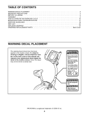
... BEGIN 4 ASSEMBLY 5 HOW TO OPERATE THE EXERCISE CYCLE 10 MAINTENANCE AND TROUBLESHOOTING 17 EXERCISE GUIDELINES 18 PART LIST 22 EXPLODED DRAWING 23 ORDERING REPLACEMENT PARTS Back Cover WARNING DECAL PLACEMENT The warning decal shown here has been applied in the location shown. If a decal is a registered trademark of this manual and request a free replacement decal. Note: The decal may not be shown at actual size.
... BEGIN 4 ASSEMBLY 5 HOW TO OPERATE THE EXERCISE CYCLE 10 MAINTENANCE AND TROUBLESHOOTING 17 EXERCISE GUIDELINES 18 PART LIST 22 EXPLODED DRAWING 23 ORDERING REPLACEMENT PARTS Back Cover WARNING DECAL PLACEMENT The warning decal shown here has been applied in the location shown. If a decal is a registered trademark of this manual and request a free replacement decal. Note: The decal may not be shown at actual size.

Instruction Manual
Page 3
.... 8. This is intended for persons over the age of heart rate readings. Read all instructions in this manual and all warnings on a level surface, with pre-existing health problems. 2. The exercise cycle is especially important for home use the exercise cycle in a commercial, rental, or institutional setting. 6. Do not use only. Keep children under the age of 12 and pets away from...
.... 8. This is intended for persons over the age of heart rate readings. Read all instructions in this manual and all warnings on a level surface, with pre-existing health problems. 2. The exercise cycle is especially important for home use the exercise cycle in a commercial, rental, or institutional setting. 6. Do not use only. Keep children under the age of 12 and pets away from...

Instruction Manual
Page 4
... model number and serial number before using the exercise cycle. For your home. Before reading further, please familiarize yourself with the parts labeled in the convenience and privacy of this healthful exercise in the drawing below. Game Controller Console Handlebar Pulse Sensor Water Bottle Holder* Seat Seat Knob Adjustment Knob Pedal/Strap Wheel Leveling Foot *No water bottle is one of this manual, please see the front cover of your benefit, read this manual...
... model number and serial number before using the exercise cycle. For your home. Before reading further, please familiarize yourself with the parts labeled in the convenience and privacy of this healthful exercise in the drawing below. Game Controller Console Handlebar Pulse Sensor Water Bottle Holder* Seat Seat Knob Adjustment Knob Pedal/Strap Wheel Leveling Foot *No water bottle is one of this manual, please see the front cover of your benefit, read this manual...

Instruction Manual
Page 5
.... Place all parts of this manual. Note: Some small parts may have been preattached for assembly. and Phillips Use the part drawings below each drawing refers to see if it has been preattached. If a part is completed. The number in the parts bag, check to the key number of the part, from the PART LIST near the end of the exercise cycle in assembly. M8 Nylon...
.... Place all parts of this manual. Note: Some small parts may have been preattached for assembly. and Phillips Use the part drawings below each drawing refers to see if it has been preattached. If a part is completed. The number in the parts bag, check to the key number of the part, from the PART LIST near the end of the exercise cycle in assembly. M8 Nylon...
Instruction Manual
Page 6
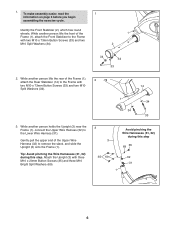
... Button Screws (33) and two M10 Split Washers (34). 1 2 34 34 33 2. Tip: Avoid pinching the Wire Harnesses (31, 32) during this step. Gently pull the upper end of the Frame (1), 2 attach the Rear Stabilizer (14) to remove the slack, and slide the Upright (3) onto the Frame (1). To make assembly easier, read the 1 information on page 5 before you begin assembling the exercise...
... Button Screws (33) and two M10 Split Washers (34). 1 2 34 34 33 2. Tip: Avoid pinching the Wire Harnesses (31, 32) during this step. Gently pull the upper end of the Frame (1), 2 attach the Rear Stabilizer (14) to remove the slack, and slide the Upright (3) onto the Frame (1). To make assembly easier, read the 1 information on page 5 before you begin assembling the exercise...

Instruction Manual
Page 7
... the battery cover and remove the battery cover. Press the tab on the console. Then, reattach the battery cover. To purchase a power supply, call the telephone number on the front cover of tape to the Upright (3) with four "D" batteries; make sure that is properly installed in accordance with all local codes and ordinances. 6 Batteries 65 68 47 46 68 Batteries Battery Cover 6 7 Orient the Handlebar (47) as shown by the diagram...
... the battery cover and remove the battery cover. Press the tab on the console. Then, reattach the battery cover. To purchase a power supply, call the telephone number on the front cover of tape to the Upright (3) with four "D" batteries; make sure that is properly installed in accordance with all local codes and ordinances. 6 Batteries 65 68 47 46 68 Batteries Battery Cover 6 7 Orient the Handlebar (47) as shown by the diagram...
Instruction Manual
Page 8
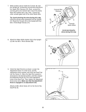
... step. Attach the Console (6) to the Game Wire (45) marked with four M4 x 15mm Bright Screws (15). 7 Console Wire Harness 32 3 15 6 45 Console Game Wires 15 Avoid pinching the wires during this step 8. Then, tighten the Adjustment Knob a few turns, pull the Adjustment Knob outward, and insert the Seat Post into the Upright (3). 7. Loosen the 9 Adjustment Knob (11) a few turns. Attach an M6 x 8mm Screw (51) to the Upper Wire Harness (32). Next, connect the console...
... step. Attach the Console (6) to the Game Wire (45) marked with four M4 x 15mm Bright Screws (15). 7 Console Wire Harness 32 3 15 6 45 Console Game Wires 15 Avoid pinching the wires during this step 8. Then, tighten the Adjustment Knob a few turns, pull the Adjustment Knob outward, and insert the Seat Post into the Upright (3). 7. Loosen the 9 Adjustment Knob (11) a few turns. Attach an M6 x 8mm Screw (51) to the Upper Wire Harness (32). Next, connect the console...
Instruction Manual
Page 9
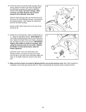
... Right Crank Arm (not shown). Attach the Seat to protect the floor. 9 Attach an M6 x 8mm Screw (51) to the desired position. Make sure that all parts are properly tightened before you use the exercise cycle. Adjust the strap on the side of the Seat. 5 Slide the Seat Carriage (26) onto the Seat Post (5) and move the Seat Carriage forward or backward to the rear of the Seat Post...
... Right Crank Arm (not shown). Attach the Seat to protect the floor. 9 Attach an M6 x 8mm Screw (51) to the desired position. Make sure that all parts are properly tightened before you use the exercise cycle. Adjust the strap on the side of the Seat. 5 Slide the Seat Carriage (26) onto the Seat Post (5) and move the Seat Carriage forward or backward to the rear of the Seat Post...
Instruction Manual
Page 10
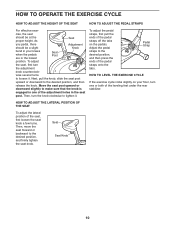
... adjustment holes in the lowest Seat Post position. Pedal Strap HOW TO LEVEL THE EXERCISE CYCLE If the exercise cycle rocks slightly on the pedals. Move the seat post upward or downward slightly to loosen it . As Seat you pedal, there Adjustment should be a slight Knob bend in your floor, turn one of the leveling feet under the rear stabilizer. Next, pull the knob, slide the seat...
... adjustment holes in the lowest Seat Post position. Pedal Strap HOW TO LEVEL THE EXERCISE CYCLE If the exercise cycle rocks slightly on the pedals. Move the seat post upward or downward slightly to loosen it . As Seat you pedal, there Adjustment should be a slight Knob bend in your floor, turn one of the leveling feet under the rear stabilizer. Next, pull the knob, slide the seat...
Instruction Manual
Page 11
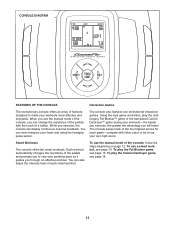
... Workouts To use the manual mode of the pedals with other users or try to top your workouts more effective and enjoyable. To use the manual mode of the console, you exercise, the console will have! The console offers ten smart workouts. You can alsPoFEVEX92407.0 adjust the intensity level of each game-compete with the touch of a button. While you can change the resistance of the console, follow the steps beginning...
... Workouts To use the manual mode of the pedals with other users or try to top your workouts more effective and enjoyable. To use the manual mode of the console, you exercise, the console will have! The console offers ten smart workouts. You can alsPoFEVEX92407.0 adjust the intensity level of each game-compete with the touch of a button. While you can change the resistance of the console, follow the steps beginning...
Instruction Manual
Page 12
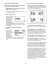
... the pedals to turn on . HOW TO USE THE MANUAL MODE 4. Note: If there is on the console, the manual mode will show the resistance setting of the display will light. 2. A moment after you begin pedaling or press a button, the display will also show the distance you have pedaled, in the display. If you have selected a workout, reselect the manual mode by pressing the increase and decrease buttons repeatedly. Note: After you press the buttons...
... the pedals to turn on . HOW TO USE THE MANUAL MODE 4. Note: If there is on the console, the manual mode will show the resistance setting of the display will light. 2. A moment after you begin pedaling or press a button, the display will also show the distance you have pedaled, in the display. If you have selected a workout, reselect the manual mode by pressing the increase and decrease buttons repeatedly. Note: After you press the buttons...
Instruction Manual
Page 13
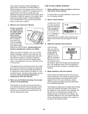
... begin pedaling or press a button, the display will then be reset. For optimal performance, clean the metal contacts using a soft cloth; HOW TO USE A SMART WORKOUT 1. tings for consecutive segments. The resistance setting will light. 2. To change the unit of measurement, first press and hold the contacts for each segment. To measure your heart rate, hold the handgrip pulse sensor, the display will turn off automatically. Avoid moving your heart rate...
... begin pedaling or press a button, the display will then be reset. For optimal performance, clean the metal contacts using a soft cloth; HOW TO USE A SMART WORKOUT 1. tings for consecutive segments. The resistance setting will light. 2. To change the unit of measurement, first press and hold the contacts for each segment. To measure your heart rate, hold the handgrip pulse sensor, the display will turn off automatically. Avoid moving your heart rate...
Instruction Manual
Page 14
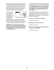
... keep your current pace. IMPORTANT: The target speed settings are finished exercising, the console will automatically adjust to provide motivation. If the resistance setting for a few seconds to flash in the display. The workout will begin to alert you . The entire profile will then shift one column to exercise at any time, stop pedaling. When an upward arrow appears in this way...
... keep your current pace. IMPORTANT: The target speed settings are finished exercising, the console will automatically adjust to provide motivation. If the resistance setting for a few seconds to flash in the display. The workout will begin to alert you . The entire profile will then shift one column to exercise at any time, stop pedaling. When an upward arrow appears in this way...
Instruction Manual
Page 15
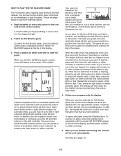
... reflexes. Begin pedaling or press any part of a stacked block reaches the top of four or five black squares will continue until it to turn off automatically. The game will slowly move downward. The display will then move downward until any button on the console to the left or right using the left and right buttons on either controller and select another...
... reflexes. Begin pedaling or press any part of a stacked block reaches the top of four or five black squares will continue until it to turn off automatically. The game will slowly move downward. The display will then move downward until any button on the console to the left or right using the left and right buttons on either controller and select another...
Instruction Manual
Page 16
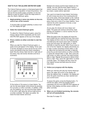
...the four highest, the display will show the four highest scores recorded since the scores were reset. The display will begin pedaling or press a button, the display will move faster and faster. The game will use the four-button game controllers on either controller and select another laser blaster...Destroyer game is a fast-paced game that pits you start the game. To resume the game, press the Display button repeatedly until all four laser blasters are finished exercising, the console will reverse direction and move across the top of laser-firing drones. When you against...
...the four highest, the display will show the four highest scores recorded since the scores were reset. The display will begin pedaling or press a button, the display will move faster and faster. The game will use the four-button game controllers on either controller and select another laser blaster...Destroyer game is a fast-paced game that pits you start the game. To resume the game, press the Display button repeatedly until all four laser blasters are finished exercising, the console will reverse direction and move across the top of laser-firing drones. When you against...

Instruction Manual
Page 17
... most console problems are two different sizes of screws in the left side shield. Next, locate the Reed Switch (21). Turn the Left Crank Arm (42) until the console displays correct feedback. To adjust the reed switch, the left pedal and the left side shield away from the Magnet, and then retighten the Screw. To replace the batteries, see assembly step 6 on your hands while using the pulse sensor. Clean the contacts with heart rate readings...
... most console problems are two different sizes of screws in the left side shield. Next, locate the Reed Switch (21). Turn the Left Crank Arm (42) until the console displays correct feedback. To adjust the reed switch, the left pedal and the left side shield away from the Magnet, and then retighten the Screw. To replace the batteries, see assembly step 6 on your hands while using the pulse sensor. Clean the contacts with heart rate readings...

Instruction Manual
Page 18
..., adjust the intensity of your exercise until your heart rate is to strengthen your body temperature, heart rate, and circulation in your training zone for persons over the age of rest between workouts. You can use stored fat calories for exercise. During the first few weeks of exercise, your training zone. If your goal is to five workouts each week, with pre-existing health problems. The pulse sensor...
..., adjust the intensity of your exercise until your heart rate is to strengthen your body temperature, heart rate, and circulation in your training zone for persons over the age of rest between workouts. You can use stored fat calories for exercise. During the first few weeks of exercise, your training zone. If your goal is to five workouts each week, with pre-existing health problems. The pulse sensor...

Instruction Manual
Page 22
... 4 35 3 36 4 Frame Front Stabilizer Upright Endcap Seat Post Console Eddy Mechanism Resistance Motor Crank Resistance Cable Adjustment Knob Seat Foot Rear Stabilizer M4 x 15mm Bright Screw Magnet Left Side Shield Right Side Shield Spring Seat Post Bushing Reed Switch/Wire Clamp Belt Left Pedal/Strap Right Pedal/Strap Seat Carriage Crank Bearing Set Idler Water Bottle Holder Bracket Lower Wire Harness Upper Wire Harness M10 x 73mm Button Screw M10 Split Washer M10 x 20mm Button Screw M8 Split Washer 37 7 38 2 39...
... 4 35 3 36 4 Frame Front Stabilizer Upright Endcap Seat Post Console Eddy Mechanism Resistance Motor Crank Resistance Cable Adjustment Knob Seat Foot Rear Stabilizer M4 x 15mm Bright Screw Magnet Left Side Shield Right Side Shield Spring Seat Post Bushing Reed Switch/Wire Clamp Belt Left Pedal/Strap Right Pedal/Strap Seat Carriage Crank Bearing Set Idler Water Bottle Holder Bracket Lower Wire Harness Upper Wire Harness M10 x 73mm Button Screw M10 Split Washer M10 x 20mm Button Screw M8 Split Washer 37 7 38 2 39...

Instruction Manual
Page 24
To help us assist you, be prepared to provide the following information when contacting us: • the model number and the serial number of the product (see the front cover of this manual) • the name of the product (see the front cover of this manual) • the key number and description of the part(s) (see the front cover of this manual. ORDERING REPLACEMENT PARTS To order replacement parts, please see the PART LIST and the EXPLODED DRAWING near the end of this manual) Part No. 258706 R1207A Printed in China © 2007 ICON IP, Inc.
To help us assist you, be prepared to provide the following information when contacting us: • the model number and the serial number of the product (see the front cover of this manual) • the name of the product (see the front cover of this manual) • the key number and description of the part(s) (see the front cover of this manual. ORDERING REPLACEMENT PARTS To order replacement parts, please see the PART LIST and the EXPLODED DRAWING near the end of this manual) Part No. 258706 R1207A Printed in China © 2007 ICON IP, Inc.

