
English Manual
Page 1
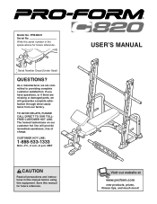
... complete customer satisfaction. CUSTOMER HOT LINE: 1-888-533-1333 Mon.-Fri., 6 a.m.-6 p.m. Write the serial number in this manual before using this manual for future reference. Serial Number Decal (Under Seat) QUESTIONS? MST CAUTION Read all precautions and instructions in the space above for future reference. As a manufacturer, we are missing or damaged parts, we will provide immediate assistance, free of charge. PFB38031...
... complete customer satisfaction. CUSTOMER HOT LINE: 1-888-533-1333 Mon.-Fri., 6 a.m.-6 p.m. Write the serial number in this manual before using this manual for future reference. Serial Number Decal (Under Seat) QUESTIONS? MST CAUTION Read all precautions and instructions in the space above for future reference. As a manufacturer, we are missing or damaged parts, we will provide immediate assistance, free of charge. PFB38031...
English Manual
Page 2
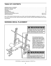
... tipping or sliding, which may cause injury, mount this manual. Place the decal on the weight bench in the location shown. TABLE OF CONTENTS WARNING DECAL PLACEMENT 2 IMPORTANT PRECAUTIONS 3 BEFORE YOU BEGIN 4 ASSEMBLY 5 ADJUSTMENTS 12 EXERCISE GUIDELINES 15 ORDERING REPLACEMENT PARTS Back Cover LIMITED WARRANTY Back Cover Note: A PART IDENTIFICATION CHART and a PART LIST/EXPLODED DRAWING is attached in the center of this bracket onto the rack base...
... tipping or sliding, which may cause injury, mount this manual. Place the decal on the weight bench in the location shown. TABLE OF CONTENTS WARNING DECAL PLACEMENT 2 IMPORTANT PRECAUTIONS 3 BEFORE YOU BEGIN 4 ASSEMBLY 5 ADJUSTMENTS 12 EXERCISE GUIDELINES 15 ORDERING REPLACEMENT PARTS Back Cover LIMITED WARRANTY Back Cover Note: A PART IDENTIFICATION CHART and a PART LIST/EXPLODED DRAWING is attached in the center of this bracket onto the rack base...
English Manual
Page 3
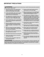
... bracket is used . 13. Read all instructions in any exercise program, consult your bench out of the way when performing an exercise that the set both barbell guides and both safety spotters at all precautions. 3. Do not use the weight bench in this manual. 2. Do not place more than 150 pounds on the leg lever or curl bar. This is especially important for home use of...
... bracket is used . 13. Read all instructions in any exercise program, consult your bench out of the way when performing an exercise that the set both barbell guides and both safety spotters at all precautions. 3. Do not use the weight bench in this manual. 2. Do not place more than 150 pounds on the leg lever or curl bar. This is especially important for home use of...
English Manual
Page 4
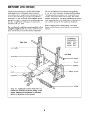
... specific results you want. Mountain Time (excluding holidays). Right Side Locking Bar Guide Bar Curl Pad Seat Leg Lever ASSEMBLED DIMENSIONS: Height: 75 in . Curl Bar 4 BEFORE YOU BEGIN Thank you have additional questions, please call our Customer Service Department toll-free at 1-888-533-1333, Monday through Friday, 6 a.m. Whether your goal is PFB38031. If you for the location of the body. The model number...
... specific results you want. Mountain Time (excluding holidays). Right Side Locking Bar Guide Bar Curl Pad Seat Leg Lever ASSEMBLED DIMENSIONS: Height: 75 in . Curl Bar 4 BEFORE YOU BEGIN Thank you have additional questions, please call our Customer Service Department toll-free at 1-888-533-1333, Monday through Friday, 6 a.m. Whether your goal is PFB38031. If you for the location of the body. The model number...
English Manual
Page 5
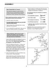
... following information and instructions: • Assembly requires two people. • For help identifying small parts, use the PART IDENTIFICATION CHART. • Tighten all parts as you assemble them, unless instructed to the Stabilizer in the assem- Note: Some parts described in the same manner. Attach another Base Cap to do otherwise. • As you assemble the weight bench, make sure you have a socket set, a set of open-end or...
... following information and instructions: • Assembly requires two people. • For help identifying small parts, use the PART IDENTIFICATION CHART. • Tighten all parts as you assemble them, unless instructed to the Stabilizer in the assem- Note: Some parts described in the same manner. Attach another Base Cap to do otherwise. • As you assemble the weight bench, make sure you have a socket set, a set of open-end or...
English Manual
Page 6
... to the bottom. Do not overtighten the Screw. 4 1 Tube 69 77 8 Handle 75 Lubricate 5. Press a 25mm Round Outer Cap (24) onto the Weight Tube. Lubricate an M10 x 68mm Button Bolt (79) with grease. Attach the Backrest Bracket (10) to the Bench 3 Frame (1) with two M10 x 68mm Button Bolts (79) and two M10 Nylon Locknuts (69). Attach the Leg Lever Bracket (7) to the Backrest 5 Tubes...
... to the bottom. Do not overtighten the Screw. 4 1 Tube 69 77 8 Handle 75 Lubricate 5. Press a 25mm Round Outer Cap (24) onto the Weight Tube. Lubricate an M10 x 68mm Button Bolt (79) with grease. Attach the Backrest Bracket (10) to the Bench 3 Frame (1) with two M10 x 68mm Button Bolts (79) and two M10 Nylon Locknuts (69). Attach the Leg Lever Bracket (7) to the Backrest 5 Tubes...
English Manual
Page 7
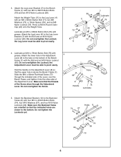
... 10 7. Do not overtighten the Locknut; Tighten the six M10 Nylon Locknuts (69) used 12 in the Bench Frame (1) and under the Backrest Bracket. Make sure that the M10 x 62mm Flat Head Screw (77) is in a notch under the Adjustment Lever (8). the Backrest Tubes must be able...the Bolt, two M10 Washers (67), and an M10 Nylon Locknut (69). Attach the Seat (13) to the Bench Frame (1) with four M6 x 38mm Screws (64) and four M6 Washers (68). Attach the Backrest Tubes (6) to the Bench Frame (1) with grease. 6. Lubricate an M10 x 155mm Button Bolt (85) with 8 an M6 x 63mm Screw (65...
... 10 7. Do not overtighten the Locknut; Tighten the six M10 Nylon Locknuts (69) used 12 in the Bench Frame (1) and under the Backrest Bracket. Make sure that the M10 x 62mm Flat Head Screw (77) is in a notch under the Adjustment Lever (8). the Backrest Tubes must be able...the Bolt, two M10 Washers (67), and an M10 Nylon Locknut (69). Attach the Seat (13) to the Bench Frame (1) with four M6 x 38mm Screws (64) and four M6 Washers (68). Attach the Backrest Tubes (6) to the Bench Frame (1) with grease. 6. Lubricate an M10 x 155mm Button Bolt (85) with 8 an M6 x 63mm Screw (65...

English Manual
Page 8
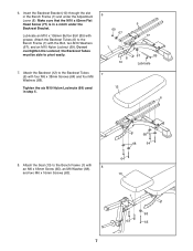
...hole in the Leg Lever (4). Attach a Guide Bar (32) to the Rack Foot (35) with soapy water. Do not tighten the Locknuts yet. Tighten the Screw. Make sure the Bolts are inserted from the other Pad Tube and the Leg Lever. Slide ...Button Bolts (60), four M10 Washers (67), and two M10 Nylon Locknuts (69). Repeat this step with 10 two M6 x 16mm Screws (63). 14 11. Attach the Curl Pad (14) to the Rack Foot with soapy water. Press a Round Angled Bushing (45) into a hole in the Leg Lever Bracket (7). Using a rubber mallet, tap the Right Upright (62), which has numbers...
...hole in the Leg Lever (4). Attach a Guide Bar (32) to the Rack Foot (35) with soapy water. Do not tighten the Locknuts yet. Tighten the Screw. Make sure the Bolts are inserted from the other Pad Tube and the Leg Lever. Slide ...Button Bolts (60), four M10 Washers (67), and two M10 Nylon Locknuts (69). Repeat this step with 10 two M6 x 16mm Screws (63). 14 11. Attach the Curl Pad (14) to the Rack Foot with soapy water. Press a Round Angled Bushing (45) into a hole in the Leg Lever Bracket (7). Using a rubber mallet, tap the Right Upright (62), which has numbers...

English Manual
Page 9
Repeat this step with 13 three M10 x 68mm Button Bolts (79), three M10 Washers (67), and two M10 Nylon Locknuts (69). Attach the other Base (28) and Rear Support (29). 13. Attach a Base Cap (9) and a Rear Support (29) to a Rear Support (29) 14 with two M10 x 93mm Button Bolts (48), an M10 Washer (67), an M10 Nylon Locknut (69...79 79 30 79 67 29 69 67 9 12. Do not tighten the Locknuts yet. Do not tighten the Locknuts yet. Attach a Base (28) to the Center Base (27) with the other Base (28) to the other Rear Support (29) in the same manner. 29 48 28 67 69 48 ...
Repeat this step with 13 three M10 x 68mm Button Bolts (79), three M10 Washers (67), and two M10 Nylon Locknuts (69). Attach the other Base (28) and Rear Support (29). 13. Attach a Base Cap (9) and a Rear Support (29) to a Rear Support (29) 14 with two M10 x 93mm Button Bolts (48), an M10 Washer (67), an M10 Nylon Locknut (69...79 79 30 79 67 29 69 67 9 12. Do not tighten the Locknuts yet. Do not tighten the Locknuts yet. Attach a Base (28) to the Center Base (27) with the other Base (28) to the other Rear Support (29) in the same manner. 29 48 28 67 69 48 ...

English Manual
Page 10
... Rear Support (29) with two M10 x 68mm Button Bolts (79) and two M10 Nylon Locknuts (69). Attach the Left Upright (31) to the Base with an M8 x 12mm Shoulder Bolt (57) and an M8 Nylon Locknut (72). Do not tighten the Locknuts yet. Identify the Left and Right Barbell Gliders (37, 81) by the position of the Right Upright...
... Rear Support (29) with two M10 x 68mm Button Bolts (79) and two M10 Nylon Locknuts (69). Attach the Left Upright (31) to the Base with an M8 x 12mm Shoulder Bolt (57) and an M8 Nylon Locknut (72). Do not tighten the Locknuts yet. Identify the Left and Right Barbell Gliders (37, 81) by the position of the Right Upright...
English Manual
Page 11
...) through the Left Barbell Glider (37), the Locking Bar (34), and the Right Barbell Glider (81). Assemble the other Weight Stop (not shown). 21. Attach the Top Bracket (36) to the Guide Bar (32) with the other Barbell Adapter (not shown). Tighten the 1/4" x 14mm Button Screws (59) and 1/4" x 9.5mm Allen Head Set Screw (66) used in the Uprights (31, 62). 18 19 81 56 67...
...) through the Left Barbell Glider (37), the Locking Bar (34), and the Right Barbell Glider (81). Assemble the other Weight Stop (not shown). 21. Attach the Top Bracket (36) to the Guide Bar (32) with the other Barbell Adapter (not shown). Tighten the 1/4" x 14mm Button Screws (59) and 1/4" x 9.5mm Allen Head Set Screw (66) used in the Uprights (31, 62). 18 19 81 56 67...
English Manual
Page 12
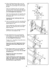
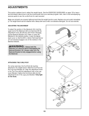
... all parts are properly tightened each exercise. WARNING: Always hold the upper end of the Backrest with the adjustment hole in the Leg Lever Bracket. Lower the Adjust- ADJUSTMENTS This section explains how to the desired position. Slide the Curl Post into the adjustment hole in the Leg Lever Bracket. The weight bench can be attached to get the most benefit from your exercise program.
... all parts are properly tightened each exercise. WARNING: Always hold the upper end of the Backrest with the adjustment hole in the Leg Lever Bracket. Lower the Adjust- ADJUSTMENTS This section explains how to the desired position. Slide the Curl Post into the adjustment hole in the Leg Lever Bracket. The weight bench can be attached to get the most benefit from your exercise program.
English Manual
Page 13
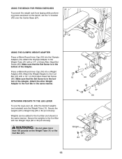
... 27 USING THE OLYMPIC WEIGHT ADAPTER Press a 48mm Round Inner Cap (16) into a Weight Adapter (49). USING THE BENCH FOR PRESS EXERCISES To prevent the weight rack from tipping while performing press exercises on the Weight Tube (11) or the Curl Bar (47). 11 15 16 66 49 16 47 66 4 Weight 11 83 13 Weights can be added to the Curl Bar with a 1/4" x 9.5mm Allen Head Set Screw (66...
... 27 USING THE OLYMPIC WEIGHT ADAPTER Press a 48mm Round Inner Cap (16) into a Weight Adapter (49). USING THE BENCH FOR PRESS EXERCISES To prevent the weight rack from tipping while performing press exercises on the Weight Tube (11) or the Curl Bar (47). 11 15 16 66 49 16 47 66 4 Weight 11 83 13 Weights can be added to the Curl Bar with a 1/4" x 9.5mm Allen Head Set Screw (66...

English Manual
Page 14
... Uprights (31, 62 [not shown]). Always secure weights with the Large Weight Clips (84). USING THE LOCKING BAR Before starting an exercise, position the Locking Bar (34) and the Safety Spotters (not shown) in the correct position for the exercise. 34 To do this, stand in front of weight (not included) onto the Barbell Adapters (41). ATTACHING WEIGHTS TO THE BARBELL OR THE WEIGHT...
... Uprights (31, 62 [not shown]). Always secure weights with the Large Weight Clips (84). USING THE LOCKING BAR Before starting an exercise, position the Locking Bar (34) and the Safety Spotters (not shown) in the correct position for the exercise. 34 To do this, stand in front of weight (not included) onto the Barbell Adapters (41). ATTACHING WEIGHTS TO THE BARBELL OR THE WEIGHT...
English Manual
Page 15
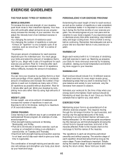
.... If you can tone your muscles by changing the number of repetitions or sets per- Exercising in each workout, as well as running on a treadmill or riding on an elliptical or exercise bike, on the next page to find the names of the muscles. An example of a balanced program is: • Plan strength training workouts on Monday, Wednesday, and Friday. • Plan...
.... If you can tone your muscles by changing the number of repetitions or sets per- Exercising in each workout, as well as running on a treadmill or riding on an elliptical or exercise bike, on the next page to find the names of the muscles. An example of a balanced program is: • Plan strength training workouts on Monday, Wednesday, and Friday. • Plan...
English Manual
Page 16
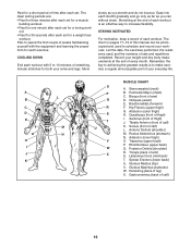
... (buttocks) W. Gastrocnemius (back of calf) K. COOLING DOWN End each workout with the equipment and learning the proper form for each set for both your weight and key body measurements at the end of each workout is to increase flexibility. List the date, the exercises performed, the resistance used to 10 minutes of your workouts. Hip Flexors (upper thigh) G. Rhomboideus (upper back) Q. The...
... (buttocks) W. Gastrocnemius (back of calf) K. COOLING DOWN End each workout with the equipment and learning the proper form for each set for both your weight and key body measurements at the end of each workout is to increase flexibility. List the date, the exercises performed, the resistance used to 10 minutes of your workouts. Hip Flexors (upper thigh) G. Rhomboideus (upper back) Q. The...

English Manual
Page 19
MONDAY Date: / / EXERCISE WEIGHT SETS REPS TUESDAY Date: / / AEROBIC EXERCISE WEDNESDAY Date: / / EXERCISE WEIGHT SETS REPS THURSDAY Date: / / AEROBIC EXERCISE FRIDAY Date: / / EXERCISE WEIGHT SETS REPS Make photocopies of this page for scheduling and recording your workouts. 19
MONDAY Date: / / EXERCISE WEIGHT SETS REPS TUESDAY Date: / / AEROBIC EXERCISE WEDNESDAY Date: / / EXERCISE WEIGHT SETS REPS THURSDAY Date: / / AEROBIC EXERCISE FRIDAY Date: / / EXERCISE WEIGHT SETS REPS Make photocopies of this page for scheduling and recording your workouts. 19
English Manual
Page 20
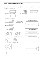
... Button Bolt (85) Important: Some parts may have been pre-assembled for shipping purposes. The number in parenthesis below each part refers to see if it has been pre-attached. If a part is provided to help you identify the small parts used in the center of the part from the PART LIST in assembly. PART IDENTIFICATION CHART This chart is not in the parts bag, check to the key number...
... Button Bolt (85) Important: Some parts may have been pre-assembled for shipping purposes. The number in parenthesis below each part refers to see if it has been pre-attached. If a part is provided to help you identify the small parts used in the center of the part from the PART LIST in assembly. PART IDENTIFICATION CHART This chart is not in the parts bag, check to the key number...
English Manual
Page 21
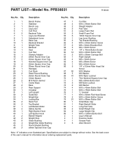
... Locknut M8 Washer M10 x 45mm Button Bolt M10 x 78mm Button Bolt "L"-bracket M10 x 62mm Flat Head Screw M10 x 25mm Button Screw M10 x 68mm Button Bolt Small Base Cap Right Barbell Glider Long Pad Tube Small Weight Clip Large Weight Clip M10 x 155mm Button Bolt User's Manual Exercise Guide Grease Pack Allen Wrench Note: "#" indicates a non-illustrated part. PFB38031 R1204A Key No. PART LIST-Model No. See the back cover of the user's manual for information about ordering replacement parts.
... Locknut M8 Washer M10 x 45mm Button Bolt M10 x 78mm Button Bolt "L"-bracket M10 x 62mm Flat Head Screw M10 x 25mm Button Screw M10 x 68mm Button Bolt Small Base Cap Right Barbell Glider Long Pad Tube Small Weight Clip Large Weight Clip M10 x 155mm Button Bolt User's Manual Exercise Guide Grease Pack Allen Wrench Note: "#" indicates a non-illustrated part. PFB38031 R1204A Key No. PART LIST-Model No. See the back cover of the user's manual for information about ordering replacement parts.
English Manual
Page 23
... order replacement parts, simply call our Customer Service Department toll-free at ICON's option, the product through Friday, 6 a.m. The MODEL NUMBER of purchase. The KEY NUMBER and DESCRIPTION of the part(s) (see the front cover of the product (PROFORM C820 weight bench) 3. This warranty extends only to give the following information: 1. ICON is not responsible or liable for indirect, special or consequential damages arising out of or in connection...
... order replacement parts, simply call our Customer Service Department toll-free at ICON's option, the product through Friday, 6 a.m. The MODEL NUMBER of purchase. The KEY NUMBER and DESCRIPTION of the part(s) (see the front cover of the product (PROFORM C820 weight bench) 3. This warranty extends only to give the following information: 1. ICON is not responsible or liable for indirect, special or consequential damages arising out of or in connection...

