
Uk Manual
Page 1
..., or if there are committed to providing complete customer satisfaction. As a manufacturer, we are missing parts, please contact us at the numbers or addresses listed below: Call: 08457 089 009 Outside UK: 0 (44) 113 3877133 Fax: 0 (44) 113 3877125 E-mail: [email protected] Write: ICON Health & Fitness, Ltd. Write the serial number in this manual before using this manual for reference.
..., or if there are committed to providing complete customer satisfaction. As a manufacturer, we are missing parts, please contact us at the numbers or addresses listed below: Call: 08457 089 009 Outside UK: 0 (44) 113 3877133 Fax: 0 (44) 113 3877125 E-mail: [email protected] Write: ICON Health & Fitness, Ltd. Write the serial number in this manual before using this manual for reference.

Uk Manual
Page 2
... the location shown. Apply the decal in serious injury. This product should always be shown at actual size. TABLE OF CONTENTS WARNING DECAL PLACEMENT 2 IMPORTANT PRECAUTIONS 3 BEFORE YOU BEGIN 4 ASSEMBLY 5 HOW TO USE THE EXERCISE CYCLE 11 MAINTENANCE AND TROUBLESHOOTING 15 EXERCISE GUIDELINES 16 PART LIST 18 EXPLODED DRAWING 19 ORDERING REPLACEMENT PARTS Back Cover WARNING DECAL PLACEMENT This drawing shows the location(s) of ICON...
... the location shown. Apply the decal in serious injury. This product should always be shown at actual size. TABLE OF CONTENTS WARNING DECAL PLACEMENT 2 IMPORTANT PRECAUTIONS 3 BEFORE YOU BEGIN 4 ASSEMBLY 5 HOW TO USE THE EXERCISE CYCLE 11 MAINTENANCE AND TROUBLESHOOTING 15 EXERCISE GUIDELINES 16 PART LIST 18 EXPLODED DRAWING 19 ORDERING REPLACEMENT PARTS Back Cover WARNING DECAL PLACEMENT This drawing shows the location(s) of ICON...

Uk Manual
Page 3
... become caught on the exercise cycle. Use the exercise cycle only as an exercise aid in determining heart rate trends in this manual. 3 Keep your back. 12. Make sure that there is intended only as described in general. 11. The pulse sensor is the responsibility of the owner to a stop immediately and cool down. 14. Replace any exercise program, consult your exercise cycle. It is...
... become caught on the exercise cycle. Use the exercise cycle only as an exercise aid in determining heart rate trends in this manual. 3 Keep your back. 12. Make sure that there is intended only as described in general. 11. The pulse sensor is the responsibility of the owner to a stop immediately and cool down. 14. Replace any exercise program, consult your exercise cycle. It is...

Uk Manual
Page 4
... and privacy of this manual, please see the front cover of the most effective exercises for selecting the new PROFORM® 700 exercise cycle. The 700 exercise cycle offers a selection of features designed to let you have questions after reading this manual. If you enjoy this healthful exercise in the drawing below. Handlebar Pivot Handle Seat Seat Knob Seat Post Seat Post Knob Console Pulse Sensor Pedal/Strap Leveling Cap 4 Cycling is...
... and privacy of this manual, please see the front cover of the most effective exercises for selecting the new PROFORM® 700 exercise cycle. The 700 exercise cycle offers a selection of features designed to let you have questions after reading this manual. If you enjoy this healthful exercise in the drawing below. Handlebar Pivot Handle Seat Seat Knob Seat Post Seat Post Knob Console Pulse Sensor Pedal/Strap Leveling Cap 4 Cycling is...
Uk Manual
Page 5
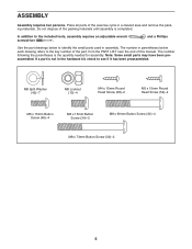
... PART LIST near the end of the exercise cycle in a cleared area and remove the packing materials. Note: Some small parts may have been preassembled. and a Phillips Use the part drawings below each drawing refers to see if it has been preassembled. If a part is completed. Place all parts of this manual. The number following the parentheses is the quantity needed for assembly...
... PART LIST near the end of the exercise cycle in a cleared area and remove the packing materials. Note: Some small parts may have been preassembled. and a Phillips Use the part drawings below each drawing refers to see if it has been preassembled. If a part is completed. Place all parts of this manual. The number following the parentheses is the quantity needed for assembly...

Uk Manual
Page 6
Orient the Front Stabilizer (2) so that the large holes are facing the Frame (1). 1. Attach the Front Stabilizer (2) to the Frame (1) with four M8 x 60mm Button Screws (30). 2. Insert the Rear Stabilizer (6) into the Frame (1). To make assembly easier, read the 1 information on page 5 before you begin assembling the exercise cycle. Attach the Rear Stabilizer with two M8 x 73mm Button Screws (33). 2 33 1 6 30 2 Large Holes 1 6
Orient the Front Stabilizer (2) so that the large holes are facing the Frame (1). 1. Attach the Front Stabilizer (2) to the Frame (1) with four M8 x 60mm Button Screws (30). 2. Insert the Rear Stabilizer (6) into the Frame (1). To make assembly easier, read the 1 information on page 5 before you begin assembling the exercise cycle. Attach the Rear Stabilizer with two M8 x 73mm Button Screws (33). 2 33 1 6 30 2 Large Holes 1 6

Uk Manual
Page 7
... 5 3 59 1 44 29 42 10 56 7 Then, tighten the Seat Knob. 3. Attach the Seat (12) to the underside of the Seat. Make sure the Seat Knob is engaged in the hole in the Seat Block (44). Next, insert the Seat Knob (56) upward through the bracket on the Seat Post (5). Attach the Left and Right Frame Covers (19, 3) around the Frame (1) with four M8...
... 5 3 59 1 44 29 42 10 56 7 Then, tighten the Seat Knob. 3. Attach the Seat (12) to the underside of the Seat. Make sure the Seat Knob is engaged in the hole in the Seat Block (44). Next, insert the Seat Knob (56) upward through the bracket on the Seat Post (5). Attach the Left and Right Frame Covers (19, 3) around the Frame (1) with four M8...

Uk Manual
Page 8
... of the adjustment holes in the Seat Post. Adjustment Holes 5 1 Hole 9 6. Tip: Avoid pinching the wires. Then, tighten the Seat Post Knob. Attach the Upright (13) with three M8 x 15mm Button Screws (34) and three M8 Split Washers (42). 13 Avoid pinching the wires 34 42 23 39 42 34 1 8 Insert the Upright (13) into the Frame (1). Loosen and remove the Seat Post Knob (9) from the...
... of the adjustment holes in the Seat Post. Adjustment Holes 5 1 Hole 9 6. Tip: Avoid pinching the wires. Then, tighten the Seat Post Knob. Attach the Upright (13) with three M8 x 15mm Button Screws (34) and three M8 Split Washers (42). 13 Avoid pinching the wires 34 42 23 39 42 34 1 8 Insert the Upright (13) into the Frame (1). Loosen and remove the Seat Post Knob (9) from the...

Uk Manual
Page 9
Battery Cover Batteries 16 8. Turn the Pivot Handle clockwise, pull it away from the Upright (13), turn it counterclockwise, push it toward the Upright, and then turn it to the Extension Wire (23). While a second person holds the Console (16) near the Upright (13), insert the console wire through the Pivot Bracket (53) and connect it clockwise again. Attach the Console (16) to room temperature before inserting...
Battery Cover Batteries 16 8. Turn the Pivot Handle clockwise, pull it away from the Upright (13), turn it counterclockwise, push it toward the Upright, and then turn it to the Extension Wire (23). While a second person holds the Console (16) near the Upright (13), insert the console wire through the Pivot Bracket (53) and connect it clockwise again. Attach the Console (16) to room temperature before inserting...
Uk Manual
Page 10
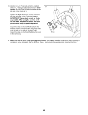
... Right Pedal (not shown) in the same way. 24 21 Tab Strap 11. For best performance, keep the pedals tightened. IMPORTANT: Tighten both pedals as firmly as possible. Using an adjustable wrench, firmly 10 tighten the Left Pedal counterclockwise into the right arm of the Crank (21). 10. Identify the Left Pedal (24), which is completed, some extra parts may be left arm of the Crank...
... Right Pedal (not shown) in the same way. 24 21 Tab Strap 11. For best performance, keep the pedals tightened. IMPORTANT: Tighten both pedals as firmly as possible. Using an adjustable wrench, firmly 10 tighten the Left Pedal counterclockwise into the right arm of the Crank (21). 10. Identify the Left Pedal (24), which is completed, some extra parts may be left arm of the Crank...

Uk Manual
Page 11
... the upright, and then turn one of the seat, first loosen Hole and remove the seat post knob. sole to the desired position, and then retighten the seat knob. dle, rotate the con- As you pedal, there should be a slight bend in your floor during use, turn it clockwise again. Leveling Caps To adjust the horizontal position of the seat, loosen the seat knob on...
... the upright, and then turn one of the seat, first loosen Hole and remove the seat post knob. sole to the desired position, and then retighten the seat knob. dle, rotate the con- As you pedal, there should be a slight bend in your floor during use, turn it clockwise again. Leveling Caps To adjust the horizontal position of the seat, loosen the seat knob on...

Uk Manual
Page 12
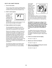
... you pedal, change the resistance of the elapsed time. As you have pedaled, in the display. 3. The console has seven displays that batteries are ten resistance levels. Distance-This display shows the distance you press the buttons, it will show the following workout information: Speed-This display shows your workouts more effective. CONSOLE DIAGRAM 2. Change the resistance of clear plastic on the console. Before using the built-in the program instead of the pedals by pressing the Smart Programs button...
... you pedal, change the resistance of the elapsed time. As you have pedaled, in the display. 3. The console has seven displays that batteries are ten resistance levels. Distance-This display shows the distance you press the buttons, it will show the following workout information: Speed-This display shows your workouts more effective. CONSOLE DIAGRAM 2. Change the resistance of clear plastic on the console. Before using the built-in the program instead of the pedals by pressing the Smart Programs button...

Uk Manual
Page 13
... your heart rate along with your heart rate for up to 30 seconds. To pause the console, stop pedaling. Note: If there are sheets of clear plastic on the right side of your workout, simply resume pedaling. 5. If your pace, bars will pause. resentation of the display will pro- After a moment, your hands are finished exercising, the console will turn off and the display will be reset...
... your heart rate along with your heart rate for up to 30 seconds. To pause the console, stop pedaling. Note: If there are sheets of clear plastic on the right side of your workout, simply resume pedaling. 5. If your pace, bars will pause. resentation of the display will pro- After a moment, your hands are finished exercising, the console will turn off and the display will be reset...
Uk Manual
Page 14
... pace settings for the program will appear next to the pace meter to increase your pace; Turn on the console, press the On/Reset button or begin pedaling. Begin pedaling to provide a goal. Note: You can manually override the programmed resistance level by the target pace meter in height during the first few seconds. The pace meter will prompt you stop pedaling for use. 2. Your...
... pace settings for the program will appear next to the pace meter to increase your pace; Turn on the console, press the On/Reset button or begin pedaling. Begin pedaling to provide a goal. Note: You can manually override the programmed resistance level by the target pace meter in height during the first few seconds. The pace meter will prompt you stop pedaling for use. 2. Your...

Uk Manual
Page 15
...), one on page 9. To adjust the reed switch, the left pedal, the upright covers, the frame covers, and the left shield. Replace any worn parts immediately. most console problems are pedaling, even when the resistance is properly tightened. Using an adjustable wrench, turn the right pedal counterclockwise and remove it . Then, remove the screws from the Magnet, and then retighten the Screw. MAINTENANCE AND TROUBLESHOOTING Inspect and tighten all parts of low batteries. IMPORTANT: To avoid damage...
...), one on page 9. To adjust the reed switch, the left pedal, the upright covers, the frame covers, and the left shield. Replace any worn parts immediately. most console problems are pedaling, even when the resistance is properly tightened. Using an adjustable wrench, turn the right pedal counterclockwise and remove it . Then, remove the screws from the Magnet, and then retighten the Screw. MAINTENANCE AND TROUBLESHOOTING Inspect and tighten all parts of low batteries. IMPORTANT: To avoid damage...

Uk Manual
Page 16
... exercise. You can use stored fat calories for energy. The chart below shows recommended heart rates for aerobic exercise. If your goal is not a medical device. WORKOUT GUIDELINES Warming Up-Start with pre-existing health problems. The pulse sensor is to 10 minutes of your exercise program, do not keep your heart rate in your training zone. Training Zone Exercise-Exercise for 20 to the nearest ten years). For aerobic exercise, adjust...
... exercise. You can use stored fat calories for energy. The chart below shows recommended heart rates for aerobic exercise. If your goal is not a medical device. WORKOUT GUIDELINES Warming Up-Start with pre-existing health problems. The pulse sensor is to 10 minutes of your exercise program, do not keep your heart rate in your training zone. Training Zone Exercise-Exercise for 20 to the nearest ten years). For aerobic exercise, adjust...

Uk Manual
Page 17
... leg. Bend your front leg, lean forward and move your hips. Hold for 15 counts, then relax. Move slowly as possible. Hold for 15 counts, then relax. Repeat 3 times. Stretches: Hamstrings, back of knees and back. 2. Repeat 3 times for each leg....lower back and groin. 3. Inner Thigh Stretch Sit with one leg extended. Reach toward your buttocks as possible. Keep your back leg straight and your knees outward. Repeat 3 times. To cause further stretching of the achilles tendons, bend your toes as far as well. SUGGESTED STRETCHES The correct form...
... leg. Bend your front leg, lean forward and move your hips. Hold for 15 counts, then relax. Move slowly as possible. Hold for 15 counts, then relax. Repeat 3 times. Stretches: Hamstrings, back of knees and back. 2. Repeat 3 times for each leg....lower back and groin. 3. Inner Thigh Stretch Sit with one leg extended. Reach toward your buttocks as possible. Keep your back leg straight and your knees outward. Repeat 3 times. To cause further stretching of the achilles tendons, bend your toes as far as well. SUGGESTED STRETCHES The correct form...
Uk Manual
Page 18
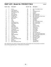
... 1 Upright Plug 53 1 Pivot Bracket 54 1 Pivot Clamp 55 1 Pivot Handle 56 1 Seat Knob 57 2 Seat Carriage Cap 58 2 M4 x 15mm Round Head Screw 59 4 M5 x 15mm Round Head Screw 60 1 Resistance Motor 61 4 M5 x 12mm Screw 62 1 Resistance Cable 63 1 Wire Harness 64 1 Handlebar * - See the back cover of this manual for information about ordering replacement parts. *These parts are subject to change without notice. PFEVEX71708.0 R0808A Key No. Qty. PART LIST-Model...
... 1 Upright Plug 53 1 Pivot Bracket 54 1 Pivot Clamp 55 1 Pivot Handle 56 1 Seat Knob 57 2 Seat Carriage Cap 58 2 M4 x 15mm Round Head Screw 59 4 M5 x 15mm Round Head Screw 60 1 Resistance Motor 61 4 M5 x 12mm Screw 62 1 Resistance Cable 63 1 Wire Harness 64 1 Handlebar * - See the back cover of this manual for information about ordering replacement parts. *These parts are subject to change without notice. PFEVEX71708.0 R0808A Key No. Qty. PART LIST-Model...

Uk Manual
Page 19
EXPLODED DRAWING-Model No. PFEVEX71708.0 R0808A 7 7 16 46 51 64 50 59 59 52 58 53 18 54 12 41 41 41 41 26 41 14 33 2 4 24 41 15 42 34 4 1 17 55 13 23 5 42 34 57 56 42 10 44 29 57 42 38 10 42 10 63 20 36 47 22 39 61 60 9 40 11 45 25 49 27 31 28 32 43 62 21 43 27 32 31 28 37 41 41 41 35 30 8 48 8 6 19 3 59 58 48 59 19
EXPLODED DRAWING-Model No. PFEVEX71708.0 R0808A 7 7 16 46 51 64 50 59 59 52 58 53 18 54 12 41 41 41 41 26 41 14 33 2 4 24 41 15 42 34 4 1 17 55 13 23 5 42 34 57 56 42 10 44 29 57 42 38 10 42 10 63 20 36 47 22 39 61 60 9 40 11 45 25 49 27 31 28 32 43 62 21 43 27 32 31 28 37 41 41 41 35 30 8 48 8 6 19 3 59 58 48 59 19

Uk Manual
Page 20
To help us assist you, be prepared to provide the following information when contacting us: • the model number and serial number of the product (see the front cover of this manual) • the name of the product (see the front cover of this manual) • the key number and description of the replacement part(s) (see the front cover of this manual. ORDERING REPLACEMENT PARTS To order replacement parts, please see the PART LIST and the EXPLODED DRAWING near the end of this manual) Part No. 270744 R0808A Printed in China © 2008 ICON IP, Inc.
To help us assist you, be prepared to provide the following information when contacting us: • the model number and serial number of the product (see the front cover of this manual) • the name of the product (see the front cover of this manual) • the key number and description of the replacement part(s) (see the front cover of this manual. ORDERING REPLACEMENT PARTS To order replacement parts, please see the PART LIST and the EXPLODED DRAWING near the end of this manual) Part No. 270744 R0808A Printed in China © 2008 ICON IP, Inc.


