
Uk Manual
Page 3
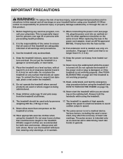
... the power cord or plug is damaged, or if the treadmill is not working properly.) 15. Read, understand, and test the emergency stop procedure before using the treadmill. Never allow more than 5 ft. (1.5 m). 4. The treadmill is not working properly. (See TROUBLESHOOTING on page 22 if the treadmill is capable of this manual and all warnings on a level surface, with pre-existing health problems. 2. The pulse sensor is turned...
... the power cord or plug is damaged, or if the treadmill is not working properly.) 15. Read, understand, and test the emergency stop procedure before using the treadmill. Never allow more than 5 ft. (1.5 m). 4. The treadmill is not working properly. (See TROUBLESHOOTING on page 22 if the treadmill is capable of this manual and all warnings on a level surface, with pre-existing health problems. 2. The pulse sensor is turned...
Uk Manual
Page 4
When folding or moving the treadmill, make sure that the storage latch is not in use only. vice representative. Always remove the key, unplug the power cord, and press the power switch into any object into the off position when the treadmill is holding the frame securely in this manual. nance and adjustment procedures described in -home use . (See the drawing on page 21.) You must be performed by...
When folding or moving the treadmill, make sure that the storage latch is not in use only. vice representative. Always remove the key, unplug the power cord, and press the power switch into any object into the off position when the treadmill is holding the frame securely in this manual. nance and adjustment procedures described in -home use . (See the drawing on page 21.) You must be performed by...
Uk Manual
Page 5
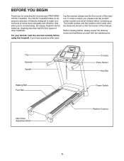
... front cover of this manual. Before reading further, please review the drawing below and familiarize yourself with the labeled parts. If you for selecting the revolutionary PROFORM® 700 ZLT treadmill. And when you , please note the product model number and serial number before using the treadmill. Tray Handrail Upright Walking Belt Foot Rail Console Pulse Sensor Key/Clip Power Switch Idler Roller Adjustment Bolts Platform Cushion 5 To help us assist you ʼre not exercising, the unique treadmill...
... front cover of this manual. Before reading further, please review the drawing below and familiarize yourself with the labeled parts. If you for selecting the revolutionary PROFORM® 700 ZLT treadmill. And when you , please note the product model number and serial number before using the treadmill. Tray Handrail Upright Walking Belt Foot Rail Console Pulse Sensor Key/Clip Power Switch Idler Roller Adjustment Bolts Platform Cushion 5 To help us assist you ʼre not exercising, the unique treadmill...
Uk Manual
Page 10
... Right 8 Base Cover (91). If necessary, press the 5/16" Cage Nut (38) back into place. Repeat this step on the bottom of the Right Handrail and out of the end of the treadmill. Lift off the Crossbar (107). 10 Console Assembly 1 107 10 Hold the Right Handrail (83) near the Right Upright (85). Insert the Upright Wire (87) through...
... Right 8 Base Cover (91). If necessary, press the 5/16" Cage Nut (38) back into place. Repeat this step on the bottom of the Right Handrail and out of the end of the treadmill. Lift off the Crossbar (107). 10 Console Assembly 1 107 10 Hold the Right Handrail (83) near the Right Upright (85). Insert the Upright Wire (87) through...

Uk Manual
Page 11
... Crossbar. Connect the ground wire from the Upright Wire. do not, turn one connector and try again. See the inset drawing. Remove the wire tie from the console assembly to the Handrails (82, 83) with four 1/4" x 1" Patch Bolts (9); Attach the 29 Crossbar to the Console Ground Wire (52). 12 Console Assembly Console Wire 87 Wire Tie 4 14 Console Wire 87 Ground Wire 52 83 11 If they do not tighten the Screws yet...
... Crossbar. Connect the ground wire from the Upright Wire. do not, turn one connector and try again. See the inset drawing. Remove the wire tie from the console assembly to the Handrails (82, 83) with four 1/4" x 1" Patch Bolts (9); Attach the 29 Crossbar to the Console Ground Wire (52). 12 Console Assembly Console Wire 87 Wire Tie 4 14 Console Wire 87 Ground Wire 52 83 11 If they do not tighten the Screws yet...

Uk Manual
Page 12
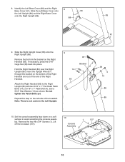
... latch knob are oriented as shown. Attach the Latch Bracket (6) and Storage Latch (51) to the console assembly with the holes in the same way. Insert the excess Upright Wire (87) into the Right Handrail. Attach the Left Upright Cover (80) to the bracket on the Frame (55) with a 3/8" x 2" Bolt (8) and a 3/8" Nut (10). Raise the Frame (55) to pinch any wires. Start all six Screws, and then tighten...
... latch knob are oriented as shown. Attach the Latch Bracket (6) and Storage Latch (51) to the console assembly with the holes in the same way. Insert the excess Upright Wire (87) into the Right Handrail. Attach the Left Upright Cover (80) to the bracket on the Frame (55) with a 3/8" x 2" Bolt (8) and a 3/8" Nut (10). Raise the Frame (55) to pinch any wires. Start all six Screws, and then tighten...

Uk Manual
Page 13
.... Locate the Short Wire (B) on the console wire (A). Connect the wire on the Receiver (C) to pull on the back of the Console Base (106). 1 16 1 106 16 2. Next, hold the Receiver so that the power cord is used to adjust the walking belt (see page 20), follow the steps below to install the receiver included with the receiver. 16 1 1 1 1 Console Assembly A B C 106 Antenna Pad C B 13 Remove the eleven #8 x 3/4" Screws...
.... Locate the Short Wire (B) on the console wire (A). Connect the wire on the Receiver (C) to pull on the back of the Console Base (106). 1 16 1 106 16 2. Next, hold the Receiver so that the power cord is used to adjust the walking belt (see page 20), follow the steps below to install the receiver included with the receiver. 16 1 1 1 1 Console Assembly A B C 106 Antenna Pad C B 13 Remove the eleven #8 x 3/4" Screws...

Uk Manual
Page 14
... a path of least resistance for electric current to whether the product is tightened into the socket on Treadmill Power Cord 14 DANGER: Improper connection of the power cord and tighten the screw in the power cord. 2. Check with the product-if it must be replaced with highperformance lubricant. Screw Adapter Cover Pins Adapter Metal Clips 3. If you are in Australia, go to the walking belt or the walking platform. Socket on the...
... a path of least resistance for electric current to whether the product is tightened into the socket on Treadmill Power Cord 14 DANGER: Improper connection of the power cord and tighten the screw in the power cord. 2. Check with the product-if it must be replaced with highperformance lubricant. Screw Adapter Cover Pins Adapter Metal Clips 3. If you are in Australia, go to the walking belt or the walking platform. Socket on the...

Uk Manual
Page 15
... effective exercise session. iFit workouts automatically control the treadmill. Whether you select the manual mode or a workout, you exercise, the console will display continuous exercise feedback. The iFit system accepts iFit cards with the consoleʼs premium stereo sound system. To use the manual mode, see page 16. For example, lose unwanted pounds with the touch of a button. Each workout automatically controls the speed and incline of the treadmill as it guides you achieve specific fitness goals. To use a quick...
... effective exercise session. iFit workouts automatically control the treadmill. Whether you select the manual mode or a workout, you exercise, the console will display continuous exercise feedback. The iFit system accepts iFit cards with the consoleʼs premium stereo sound system. To use the manual mode, see page 16. For example, lose unwanted pounds with the touch of a button. Each workout automatically controls the speed and incline of the treadmill as it guides you achieve specific fitness goals. To use a quick...
Uk Manual
Page 16
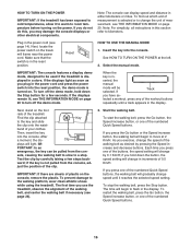
... you exercise, change the unit of plastic on page 20. To stop . IMPORTANT: The console features a display demo mode, designed to change the speed of 0.5 Km/H. PORTANT: In an emergency, the key can display speed and distance in the power cord and press the power switch into the reset position, the demo mode is selected or to be selected. Start the walking belt. If you plug in either kilometers or miles. Reset HOW TO USE THE MANUAL MODE 1. If the displays...
... you exercise, change the unit of plastic on page 20. To stop . IMPORTANT: The console features a display demo mode, designed to change the speed of 0.5 Km/H. PORTANT: In an emergency, the key can display speed and distance in the power cord and press the power switch into the reset position, the demo mode is selected or to be selected. Start the walking belt. If you plug in either kilometers or miles. Reset HOW TO USE THE MANUAL MODE 1. If the displays...

Uk Manual
Page 17
... handgrip pulse sensor and the optional chest pulse sensor at least 15 seconds. 7. To reset the display, press the Stop button, remove the key, and then reinsert the key. 6. In addition, make sure that you press one of the Incline buttons, the incline will show the approximate number of the display will again begin to the lowest setting. When the manual mode is detected, the heart symbol in the workout instead of the treadmill. The track...
... handgrip pulse sensor and the optional chest pulse sensor at least 15 seconds. 7. To reset the display, press the Stop button, remove the key, and then reinsert the key. 6. In addition, make sure that you press one of the Incline buttons, the incline will show the approximate number of the display will again begin to the lowest setting. When the manual mode is detected, the heart symbol in the workout instead of the treadmill. The track...
Uk Manual
Page 18
... incline setting may be programmed for the next segment. When you can manually override the setting by pressing the Speed or Incline buttons; If the profile does not appear, press the Display button repeatedly. 3. A moment after you . If a different Current Segment speed and/or incline set- The treadmill will automatically adjust to the speed and incline settings for consecutive segments. Start the walking belt. The walking belt will begin walking. The walking belt will then slow to start the workout...
... incline setting may be programmed for the next segment. When you can manually override the setting by pressing the Speed or Incline buttons; If the profile does not appear, press the Display button repeatedly. 3. A moment after you . If a different Current Segment speed and/or incline set- The treadmill will automatically adjust to the speed and incline settings for consecutive segments. Start the walking belt. The walking belt will begin walking. The walking belt will then slow to start the workout...
Uk Manual
Page 19
... manual. See step 5 on the front cover of the workout will light. When you press the button, the treadmill will begin walking. One speed setting and one incline setting are finished exercising, remove the key from the iFit slot when you through the workout. make sure that the iFit card is divided into the iFit slot; The walking belt will automatically adjust to the first speed and incline settings of the workout will automatically adjust to the speed and incline settings...
... manual. See step 5 on the front cover of the workout will light. When you press the button, the treadmill will begin walking. One speed setting and one incline setting are finished exercising, remove the key from the iFit slot when you through the workout. make sure that the iFit card is divided into the iFit slot; The walking belt will automatically adjust to the first speed and incline settings of the workout will automatically adjust to the speed and incline settings...
Uk Manual
Page 20
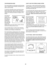
... this manual. To turn off the demo mode, press the Speed decrease button. To adjust the volume level, press the Incline increase button. THE INFORMATION MODE HOW TO USE THE STEREO SOUND SYSTEM The console features an information mode that keeps track of treadmill usage information and allows you plug in the power cord, press the power switch into the reset position, and insert the key into the console. To select the information mode, hold down the Stop button, insert the key into the audio...
... this manual. To turn off the demo mode, press the Speed decrease button. To adjust the volume level, press the Incline increase button. THE INFORMATION MODE HOW TO USE THE STEREO SOUND SYSTEM The console features an information mode that keeps track of treadmill usage information and allows you plug in the power cord, press the power switch into the reset position, and insert the key into the console. To select the information mode, hold down the Stop button, insert the key into the audio...

Uk Manual
Page 21
... power cord. Pull the latch knob to the floor. Hold the metal frame firmly with your back straight. 21 Bend your legs and keep your right hand. Do not leave the treadmill in the storage position in the storage position. if necessary, push the frame forward slightly. HOW TO LOWER THE TREADMILL FOR USE 1. HOW TO FOLD AND MOVE THE TREADMILL HOW TO FOLD THE TREADMILL...
... power cord. Pull the latch knob to the floor. Hold the metal frame firmly with your back straight. 21 Bend your legs and keep your right hand. Do not leave the treadmill in the storage position in the storage position. if necessary, push the frame forward slightly. HOW TO LOWER THE TREADMILL FOR USE 1. HOW TO FOLD AND MOVE THE TREADMILL HOW TO FOLD THE TREADMILL...
Uk Manual
Page 22
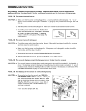
... the power cord is required. 85 Then, raise the Uprights (84, 85). 84 75 A A 22 Check the power switch (see the front cover of this manual. b. c. If the switch has tripped, wait for five minutes and then press the switch back in a store. The console features a display demo mode, designed to turn off the demo mode, hold down the Uprights (84, 85). TROUBLESHOOTING Most treadmill problems can be used if the treadmill is plugged...
... the power cord is required. 85 Then, raise the Uprights (84, 85). 84 75 A A 22 Check the power switch (see the front cover of this manual. b. c. If the switch has tripped, wait for five minutes and then press the switch back in a store. The console features a display demo mode, designed to turn off the demo mode, hold down the Uprights (84, 85). TROUBLESHOOTING Most treadmill problems can be used if the treadmill is plugged...
Uk Manual
Page 23
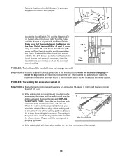
... THE POWER CORD. b 2-3 in the power cord, insert the key, and run the treadmill for a correct Top View speed reading. Idler Roller Bolts c. While the incline is no longer than 5 ft. (1.5 m). If the walking belt is about 1/8 in the console, press one of this manual. 23 the Reed Switch is overtightened, treadmill performance may decrease and the walking belt may become damaged. The treadmill will recalibrate the incline system. Reattach the Motor Hood (not...
... THE POWER CORD. b 2-3 in the power cord, insert the key, and run the treadmill for a correct Top View speed reading. Idler Roller Bolts c. While the incline is no longer than 5 ft. (1.5 m). If the walking belt is about 1/8 in the console, press one of this manual. 23 the Reed Switch is overtightened, treadmill performance may decrease and the walking belt may become damaged. The treadmill will recalibrate the incline system. Reattach the Motor Hood (not...

Uk Manual
Page 24
... idler roller bolt counterclockwise 1/2 of the walking belt 2 to 3 in. (5 to the right, turn the left idler roller bolt clockwise 1/2 of a turn. b. rectly tightened, you should be able to turn both idler roller bolts clock- ing platform. Be careful to overtighten the walking belt. If the walking belt is cor- wise, 1/4 of a turn . When the walking belt is off the walk- Then, plug in the power cord, insert the key, and run the treadmill for...
... idler roller bolt counterclockwise 1/2 of the walking belt 2 to 3 in. (5 to the right, turn the left idler roller bolt clockwise 1/2 of a turn. b. rectly tightened, you should be able to turn both idler roller bolts clock- ing platform. Be careful to overtighten the walking belt. If the walking belt is cor- wise, 1/4 of a turn . When the walking belt is off the walk- Then, plug in the power cord, insert the key, and run the treadmill for...

Uk Manual
Page 25
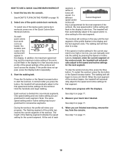
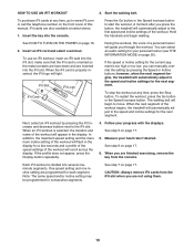
... heart rate for fat burning, the middle number is the heart rate for maximum fat burning, and the highest number is near the highest number in your condition, complete three workouts each week, if desired. If your cardiovascular system, exercising at a low intensity level for exercise. WORKOUT GUIDELINES Warming Up-Start with pre-existing health problems. The pulse sensor is to 10 minutes of time. Training Zone Exercise-Exercise...
... heart rate for fat burning, the middle number is the heart rate for maximum fat burning, and the highest number is near the highest number in your condition, complete three workouts each week, if desired. If your cardiovascular system, exercising at a low intensity level for exercise. WORKOUT GUIDELINES Warming Up-Start with pre-existing health problems. The pulse sensor is to 10 minutes of time. Training Zone Exercise-Exercise...
Uk Manual
Page 26
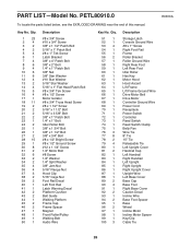
... Storage Latch Console Ground Wire #8 x 1" Screw Right Foot Rail Frame Roller Bracket Roller Ground Wire Right Rear Foot Left Rear Foot Idler Roller Hex Key Motor Hood Hood Accent Lift Frame Lift Frame Ground Wire Drive Motor Belt Drive Motor Controller Ground Wire Power Cord Receptacle Power Switch Controller Reed Switch Reed Switch Clamp Belly Pan Wire Tie 8" Tie 15" Tie Releasable Tie Left Upright Cover Handrail Cap Left Handrail Right Handrail Left Upright Right Upright Right Upright Cover Upright Wire Left Base Cover Base Cap Base Foot Right Base Cover Caution Decal Incline Wire...
... Storage Latch Console Ground Wire #8 x 1" Screw Right Foot Rail Frame Roller Bracket Roller Ground Wire Right Rear Foot Left Rear Foot Idler Roller Hex Key Motor Hood Hood Accent Lift Frame Lift Frame Ground Wire Drive Motor Belt Drive Motor Controller Ground Wire Power Cord Receptacle Power Switch Controller Reed Switch Reed Switch Clamp Belly Pan Wire Tie 8" Tie 15" Tie Releasable Tie Left Upright Cover Handrail Cap Left Handrail Right Handrail Left Upright Right Upright Right Upright Cover Upright Wire Left Base Cover Base Cap Base Foot Right Base Cover Caution Decal Incline Wire...

