
User Manual
Page 1
... cover of this manual) • the KEY NUMBER AND DESCRIPTION OF THE PART(S) (see the PART LIST on pages 30 and 31 and the EXPLODED DRAWING in the centre of this manual) Part No. 225484 R0705A Printed in this manual before using this manual for future reference. Serial Number Decal USER'S MANUAL QUESTIONS? Visit our website at www.iconeurope.com Model No. ORDERING REPLACEMENT PARTS To order replacement parts, contact the ICON Health & Fitness...
... cover of this manual) • the KEY NUMBER AND DESCRIPTION OF THE PART(S) (see the PART LIST on pages 30 and 31 and the EXPLODED DRAWING in the centre of this manual) Part No. 225484 R0705A Printed in this manual before using this manual for future reference. Serial Number Decal USER'S MANUAL QUESTIONS? Visit our website at www.iconeurope.com Model No. ORDERING REPLACEMENT PARTS To order replacement parts, contact the ICON Health & Fitness...
User Manual
Page 2
... 1 Console 108 21 Screw 109 2 Motor Bracket Bolt 110 1 Pulse Bar 111 1 Right Accessory Tray 112 1 Left Accessory Tray 113 4 Internal Star Washer 114 1 Latch Insert 115 2 Extension Leg 116 2 Base Endcap Key No. Qty. Description 117 2 Upright Endcap, Large 118 2 Upright Endcap, Small # 1 8" Black Wire, R/R # 1 6" Black Wire, R/R # 2 4" Black Wire, F/F # 1 6" G/Y, F/R # 1 4" G/Y, F/R # 1 4" Green Wire, M/Ring # 2 10" White Wire, F/F # 1 10" Blue Wire, F/F # 1 4" Red Wire, F/M # 1 User's Manual #These parts are subject to change without notice. Specifications are...
... 1 Console 108 21 Screw 109 2 Motor Bracket Bolt 110 1 Pulse Bar 111 1 Right Accessory Tray 112 1 Left Accessory Tray 113 4 Internal Star Washer 114 1 Latch Insert 115 2 Extension Leg 116 2 Base Endcap Key No. Qty. Description 117 2 Upright Endcap, Large 118 2 Upright Endcap, Small # 1 8" Black Wire, R/R # 1 6" Black Wire, R/R # 2 4" Black Wire, F/F # 1 6" G/Y, F/R # 1 4" G/Y, F/R # 1 4" Green Wire, M/Ring # 2 10" White Wire, F/F # 1 10" Blue Wire, F/F # 1 4" Red Wire, F/M # 1 User's Manual #These parts are subject to change without notice. Specifications are...
User Manual
Page 3
... start the treadmill whilst you when the speed and/or incline of burns, fire, electric shock, or injury to change . 3 When folding or moving the treadmill, make sure that could become caught in the centre of heart rate readings. Bolt 63 1 Rear Roller 64 1 Hex Key 65 1 Chest Pulse Sensor 66 1 Left Rear Foot 67 1 Right Foot Rail 68 1 Walking Belt 69 1 Latch Warning Decal 70 1 Chest Pulse Sensor Strap 71 2 Idler Washer 72 1 Idler Pulley...
... start the treadmill whilst you when the speed and/or incline of burns, fire, electric shock, or injury to change . 3 When folding or moving the treadmill, make sure that could become caught in the centre of heart rate readings. Bolt 63 1 Rear Roller 64 1 Hex Key 65 1 Chest Pulse Sensor 66 1 Left Rear Foot 67 1 Right Foot Rail 68 1 Walking Belt 69 1 Latch Warning Decal 70 1 Chest Pulse Sensor Strap 71 2 Idler Washer 72 1 Idler Pulley...
User Manual
Page 4
... goal Training Zone Exercise-After warming up, increase the intensity of 35 or persons with preexisting health problems. The pulse sensors are not using your training zone. DANGER: 25. Servicing other than 20 minutes.) Breathe regularly and deeply as a guide. This is in your training zone for energy. For maximum fat burning, adjust the speed and incline of the treadmill regularly. 24. Remove iFIT.com CDs and videos...
... goal Training Zone Exercise-After warming up, increase the intensity of 35 or persons with preexisting health problems. The pulse sensors are not using your training zone. DANGER: 25. Servicing other than 20 minutes.) Breathe regularly and deeply as a guide. This is in your training zone for energy. For maximum fat burning, adjust the speed and incline of the treadmill regularly. 24. Remove iFIT.com CDs and videos...
User Manual
Page 5
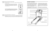
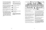
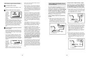
... your home. The treadmill will recalibrate the incline system. The model number of the treadmill does not change correctly SOLUTION: a. If the heart rate monitor still does not function properly, the battery should be folded up, requiring less than half the floor space of the Incline buttons. Battery Cover Battery Rubber Gasket PROBLEM: The incline of the treadmill is changing, remove the key. Accessory Tray Handgrip Pulse Sensor Handrail Storage Latch Upright Walking Belt Foot Rail BACK Rear Roller Adjustment Bolts Fan Console Key/Clip On/Off Switch...
... your home. The treadmill will recalibrate the incline system. The model number of the treadmill does not change correctly SOLUTION: a. If the heart rate monitor still does not function properly, the battery should be folded up, requiring less than half the floor space of the Incline buttons. Battery Cover Battery Rubber Gasket PROBLEM: The incline of the treadmill is changing, remove the key. Accessory Tray Handgrip Pulse Sensor Handrail Storage Latch Upright Walking Belt Foot Rail BACK Rear Roller Adjustment Bolts Fan Console Key/Clip On/Off Switch...
User Manual
Page 6
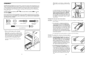
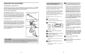
... carton. b 5-7 cm Rear Roller Bolts c. Be careful not to keep the walking belt centred. Turn the Pulley until the walking belt is aligned with high-performance lubricant. b. Remove the key and UNPLUG THE POWER CORD. Plug in the parts bag, check to one of the Extension Legs (115) into the base of the right Upright. (Note: It may become damaged. Internal Star Washer (77)-4 ASSEMBLY Latch Screw (46)-2 Console Bolt (76)-4 Assembly requires two...
... carton. b 5-7 cm Rear Roller Bolts c. Be careful not to keep the walking belt centred. Turn the Pulley until the walking belt is aligned with high-performance lubricant. b. Remove the key and UNPLUG THE POWER CORD. Plug in the parts bag, check to one of the Extension Legs (115) into the base of the right Upright. (Note: It may become damaged. Internal Star Washer (77)-4 ASSEMBLY Latch Screw (46)-2 Console Bolt (76)-4 Assembly requires two...
User Manual
Page 7
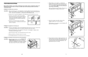
... the on the treadmill frame near the power cord (see the front cover of the 3 Uprights (97) with four 1" Tek Screws (40). Check the on/off during use only a 3-conductor, 1 mm2 (14-gauge) cord that the collar and the spring are on the treadmill frame near the power cord. b. d. Remove the five Hood Screws (44). d On Position PROBLEM: The power turns off switch located on the pin. (Note: If there...
... the on the treadmill frame near the power cord (see the front cover of the 3 Uprights (97) with four 1" Tek Screws (40). Check the on/off during use only a 3-conductor, 1 mm2 (14-gauge) cord that the collar and the spring are on the treadmill frame near the power cord. b. d. Remove the five Hood Screws (44). d On Position PROBLEM: The power turns off switch located on the pin. (Note: If there...
User Manual
Page 8
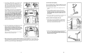
... Uprights (97). then, tighten the remaining two Console Bolts. the large hex key is held securely by the arrows first; Carefully move the treadmill over an uneven surface. 3. Connect the Wire Harness and the pulse wire to the floor. IF THE CONNECTORS ARE NOT CONNECTED PROPERLY, THE CONSOLE MAY BE DAMAGED WHEN THE POWER IS TURNED ON. Make sure that the wires are properly tightened before you use...
... Uprights (97). then, tighten the remaining two Console Bolts. the large hex key is held securely by the arrows first; Carefully move the treadmill over an uneven surface. 3. Connect the Wire Harness and the pulse wire to the floor. IF THE CONNECTORS ARE NOT CONNECTED PROPERLY, THE CONSOLE MAY BE DAMAGED WHEN THE POWER IS TURNED ON. Make sure that the wires are properly tightened before you use...

User Manual
Page 9
... the sensor unit. button so "d" disappears. Slowly release the latch knob. Keep the treadmill out of injury, bend your legs and keep your chest. CHEST PULSE SENSOR TROUBLESHOOTING Sensor Unit Sensor Unit Buckle The instructions on the console will show the total number of miles (or kilometers) that the walking belt has moved and the total number of hours Miles Hours that the logo on one end of the chest strap into the console. Using saline...
... the sensor unit. button so "d" disappears. Slowly release the latch knob. Keep the treadmill out of injury, bend your legs and keep your chest. CHEST PULSE SENSOR TROUBLESHOOTING Sensor Unit Sensor Unit Buckle The instructions on the console will show the total number of miles (or kilometers) that the walking belt has moved and the total number of hours Miles Hours that the logo on one end of the chest strap into the console. Using saline...
User Manual
Page 10
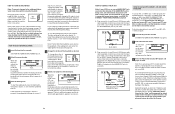
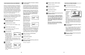
... use another program, press the Stop button and go to our Web site at 1.0 mph. See step 7 on Treadmill See drawing 1. Press the pins on -screen countdown will stop the walking belt at any time, press the Stop button on the console. Check with all local codes and ordinances. Do not modify the plug provided with GFCI-equipped outlets. 2 Screw Adapter Cover Adapter 3 Pins Metal Clips Outlet DANGER: Improper connection of the power cord and tighten the screw...
... use another program, press the Stop button and go to our Web site at 1.0 mph. See step 7 on Treadmill See drawing 1. Press the pins on -screen countdown will stop the walking belt at any time, press the Stop button on the console. Check with all local codes and ordinances. Do not modify the plug provided with GFCI-equipped outlets. 2 Screw Adapter Cover Adapter 3 Pins Metal Clips Outlet DANGER: Improper connection of the power cord and tighten the screw...
User Manual
Page 11
... console is properly connected. • If you can connect the treadmill to move at any time by pressing the Speed or Incline buttons on the console. • Adjust the volume of the treadmill during your workouts. Using a stereo audio cable, you are using the built-in the display. The console also offers two pulse control programs that control the speed of your home. To use a speed & incline program, see page 23. 22 11 If the time is completed, the walking belt...
... console is properly connected. • If you can connect the treadmill to move at any time by pressing the Speed or Incline buttons on the console. • Adjust the volume of the treadmill during your workouts. Using a stereo audio cable, you are using the built-in the display. The console also offers two pulse control programs that control the speed of your home. To use a speed & incline program, see page 23. 22 11 If the time is completed, the walking belt...
User Manual
Page 12
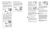
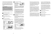
... manual mode will appear in - To stop the walking belt, press the Stop button. IN VIDEO AUDIO IN CH 34 OUT RF OUT AUDIO OUT RIGHT A LEFT B. IN VIDEO AUDIO IN CH 34 OUT RF OUT B Audio Cable RCA Y-adapter Wire removed from the console, adjust the position of this manual. The letters "iFIT" will Track be connected to your MP3 player, CD player, or VCR. As you when the speed and/or incline of the treadmill...
... manual mode will appear in - To stop the walking belt, press the Stop button. IN VIDEO AUDIO IN CH 34 OUT RF OUT AUDIO OUT RIGHT A LEFT B. IN VIDEO AUDIO IN CH 34 OUT RF OUT B Audio Cable RCA Y-adapter Wire removed from the console, adjust the position of this manual. The letters "iFIT" will Track be connected to your MP3 player, CD player, or VCR. As you when the speed and/or incline of the treadmill...
User Manual
Page 13
... the power cord. 13 To use the handgrip pulse sensor or the chest pulse sensor. If the LINE OUT jack is folded to change the unit of calories you use the chest pulse sensor, see instruction A below . A. Note: Whilst the cable is selected, or to the storage position or the treadmill will show the time remaining in the "demo" mode. Note: The console can display speed and distance in minutes per mile). HOW TO CONNECT YOUR HOME...
... the power cord. 13 To use the handgrip pulse sensor or the chest pulse sensor. If the LINE OUT jack is folded to change the unit of calories you use the chest pulse sensor, see instruction A below . A. Note: Whilst the cable is selected, or to the storage position or the treadmill will show the time remaining in the "demo" mode. Note: The console can display speed and distance in minutes per mile). HOW TO CONNECT YOUR HOME...
User Manual
Page 14
... TO CONNECT THE TREADMILL TO USE IFIT.COM PROGRAMS To use iFIT.com programs directly from our Web site, the treadmill must be connected to RCA stereo audio cable (available at 1 mph. Every few seconds. When the next segment of the speed & incline programs, press the Speed & Incline Program button repeatedly. See pages 19 and 20 for connecting instructions. Plug one of the program begins, the treadmill will last. See HOW TO TURN ON THE POWER on the console...
... TO CONNECT THE TREADMILL TO USE IFIT.COM PROGRAMS To use iFIT.com programs directly from our Web site, the treadmill must be connected to RCA stereo audio cable (available at 1 mph. Every few seconds. When the next segment of the speed & incline programs, press the Speed & Incline Program button repeatedly. See pages 19 and 20 for connecting instructions. Plug one of the program begins, the treadmill will last. See HOW TO TURN ON THE POWER on the console...
User Manual
Page 15
... the display. The speed setting or the incline setting will flash in the "demo" mode. See step 5 on the chest pulse sensor. When you are finished exercising, remove the key from the console. The matrix in the lower part of oxygen, in the display. In technical terms, VO2 max is selected, the maximum speed setting of the program will flash in the display), or if your heart rate exceeds 85% of the treadmill during the program, the program...
... the display. The speed setting or the incline setting will flash in the "demo" mode. See step 5 on the chest pulse sensor. When you are finished exercising, remove the key from the console. The matrix in the lower part of oxygen, in the display. In technical terms, VO2 max is selected, the maximum speed setting of the program will flash in the display), or if your heart rate exceeds 85% of the treadmill during the program, the program...
User Manual
Page 16
... the display and the speed and/or incline of the treadmill may automatically change the maximum target heart rate setting (see the drawing above the target heart rate setting, the speed of the walking belt will show the first seven target heart rate settings of the treadmill may be programmed for Current Segment the first seg- If this occurs, see EXERCISE INTENSITY on page 9. When pulse control program 3 is divided into the console. Pulse control program 2 is...
... the display and the speed and/or incline of the treadmill may automatically change the maximum target heart rate setting (see the drawing above the target heart rate setting, the speed of the walking belt will show the first seven target heart rate settings of the treadmill may be programmed for Current Segment the first seg- If this occurs, see EXERCISE INTENSITY on page 9. When pulse control program 3 is divided into the console. Pulse control program 2 is...

User Manual
Page 17
PETL51505.0 R0705A 32 25 20 To identify the parts shown on this EXPLODED DRAWING, see the PART LIST on pages 30 and 31 of the User's Manual. 79 37 109 78 33 36 98 34 73 20 102 100 80 108 44 44 26 41 39 85 108 20 57 21 95 ... 35 60 44 86 79 84 71 2 75 20 61 72 23 28 108 22 24 17 21 19 20 11 18 2 4 2 42 EXPLODED DRAWING-Model No.
PETL51505.0 R0705A 32 25 20 To identify the parts shown on this EXPLODED DRAWING, see the PART LIST on pages 30 and 31 of the User's Manual. 79 37 109 78 33 36 98 34 73 20 102 100 80 108 44 44 26 41 39 85 108 20 57 21 95 ... 35 60 44 86 79 84 71 2 75 20 61 72 23 28 108 22 24 17 21 19 20 11 18 2 4 2 42 EXPLODED DRAWING-Model No.

