
English Manual
Page 3
... specifications described on your treadmill before using your treadmill. Never move the walking belt while the power is not working properly. (See TROUBLESHOOTING on page 16). 9. Never use a properly functioning surge suppressor could become caught in a garage or covered patio, or near water. 6. When connecting the power cord (see HOW TO TURN ON THE POWER on page 22 if the treadmill is turned off. No other appliance 17. The pulse sensor...
... specifications described on your treadmill before using your treadmill. Never move the walking belt while the power is not working properly. (See TROUBLESHOOTING on page 16). 9. Never use a properly functioning surge suppressor could become caught in a garage or covered patio, or near water. 6. When connecting the power cord (see HOW TO TURN ON THE POWER on page 22 if the treadmill is turned off. No other appliance 17. The pulse sensor...
English Manual
Page 4
... properly tighten all parts of the circuit breaker.) 21. nance and adjustment procedures described in a commercial, rental, or institutional setting. 23. Do not use only. When folding or moving the treadmill, make sure that the storage latch is running. Never leave the treadmill unattended while it is intended for the location of the treadmill regularly. 20. Always remove the key, unplug the power cord, and switch the reset/off...
... properly tighten all parts of the circuit breaker.) 21. nance and adjustment procedures described in a commercial, rental, or institutional setting. 23. Do not use only. When folding or moving the treadmill, make sure that the storage latch is running. Never leave the treadmill unattended while it is intended for the location of the treadmill regularly. 20. Always remove the key, unplug the power cord, and switch the reset/off...
English Manual
Page 5
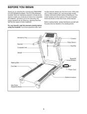
... with the parts that are shown on the front cover of this manual. For your workouts at home more enjoyable and effective. Accessory Tray Handrail Crosswalk Arm Upright Walking Belt Foot Rail Idler Roller Adjustment Bolts Console Pulse Sensor Key/Clip Reset/Off Circuit Breaker Power Cord Platform Cushion 5 If you for selecting the revolutionary PROFORM® 570 CROSSWALK treadmill. To help us assist you ʼre not exercising, the unique treadmill can be folded up, requiring...
... with the parts that are shown on the front cover of this manual. For your workouts at home more enjoyable and effective. Accessory Tray Handrail Crosswalk Arm Upright Walking Belt Foot Rail Idler Roller Adjustment Bolts Console Pulse Sensor Key/Clip Reset/Off Circuit Breaker Power Cord Platform Cushion 5 If you for selecting the revolutionary PROFORM® 570 CROSSWALK treadmill. To help us assist you ʼre not exercising, the unique treadmill can be folded up, requiring...
English Manual
Page 6
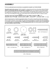
... #8 x 1/2" Screw (2)-2 #8 x 3/4" Screw (1)-6 #8 x 3/4" Tek Screw (13)-2 #8 x 1" Tek Screw (6)-4 #10 x 3/4" Screw (4)-4 5/16" x 1 3/4" Bolt (5)-4 3/8" x 1 3/4" Bolt (7)-1 3/8" x 2" Bolt (9)-3 3/8" x 4" Bolt (8)-4 6 Do not dispose of the parts to the top of the treadmill walking belt is the quantity needed for assembly. The number in a cleared area and remove all packing materials. To avoid damaging plastic parts, do not use power tools for assembly. Assembly requires two persons. This is lubricant on top of this manual. Assembly requires the included hex key and your...
... #8 x 1/2" Screw (2)-2 #8 x 3/4" Screw (1)-6 #8 x 3/4" Tek Screw (13)-2 #8 x 1" Tek Screw (6)-4 #10 x 3/4" Screw (4)-4 5/16" x 1 3/4" Bolt (5)-4 3/8" x 1 3/4" Bolt (7)-1 3/8" x 2" Bolt (9)-3 3/8" x 4" Bolt (8)-4 6 Do not dispose of the parts to the top of the treadmill walking belt is the quantity needed for assembly. The number in a cleared area and remove all packing materials. To avoid damaging plastic parts, do not use power tools for assembly. Assembly requires two persons. This is lubricant on top of this manual. Assembly requires the included hex key and your...

English Manual
Page 11
.... Set the console assembly face down on the Left and Right Uprights (77, 92). Lift off the Pulse Bar (110). IF THE CONNECTORS ARE NOT CONNECTED PROPERLY, THE CONSOLE MAY BE DAMAGED WHEN THE POWER IS TURNED ON. Set the Pulse Bar (110) on a soft surface to the Wire Harness (91). Remove the two #8 x 3/4" Screws (1). 11. Start all four Screws before firmly tightening any of the Pulse Bar (110). 13 Console Console Assembly Wire Ground Wire...
.... Set the console assembly face down on the Left and Right Uprights (77, 92). Lift off the Pulse Bar (110). IF THE CONNECTORS ARE NOT CONNECTED PROPERLY, THE CONSOLE MAY BE DAMAGED WHEN THE POWER IS TURNED ON. Set the Pulse Bar (110) on a soft surface to the Wire Harness (91). Remove the two #8 x 3/4" Screws (1). 11. Start all four Screws before firmly tightening any of the Pulse Bar (110). 13 Console Console Assembly Wire Ground Wire...

English Manual
Page 12
... the indicated location and press the Right Handrail Cover (55) against the console assembly. be careful not to the Pulse Bar (110) with a sticker. Then, raise the Uprights (77, 92). Tighten a #8 x 1/2" Screw (2) into the Left and Right Uprights (77, 92) and the console assembly. Attach the Left Handrail Cover (78) in step 11. do not overtighten the Screws. Attach the console assembly to overtighten the Screw. Set the console assembly on the console assembly. Console Assembly 110 1 1 92...
... the indicated location and press the Right Handrail Cover (55) against the console assembly. be careful not to the Pulse Bar (110) with a sticker. Then, raise the Uprights (77, 92). Tighten a #8 x 1/2" Screw (2) into the Left and Right Uprights (77, 92) and the console assembly. Attach the Left Handrail Cover (78) in step 11. do not overtighten the Screws. Attach the console assembly to overtighten the Screw. Set the console assembly on the console assembly. Console Assembly 110 1 1 92...
English Manual
Page 14
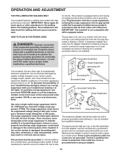
... reduce the risk of this manual and order part number 146148, or see your homeʼs power. Failure to a 2-pole receptacle as a transient voltage surge suppressor (TVSS). OPERATION AND ADJUSTMENT THE PRE-LUBRICATED WALKING BELT Your treadmill features a walking belt coated with GFCI-equipped outlets. This product is grounded before using an adapter. 14 Plug the power cord into a surge suppressor, and plug the surge suppressor into an...
... reduce the risk of this manual and order part number 146148, or see your homeʼs power. Failure to a 2-pole receptacle as a transient voltage surge suppressor (TVSS). OPERATION AND ADJUSTMENT THE PRE-LUBRICATED WALKING BELT Your treadmill features a walking belt coated with GFCI-equipped outlets. This product is grounded before using an adapter. 14 Plug the power cord into a surge suppressor, and plug the surge suppressor into an...
English Manual
Page 15
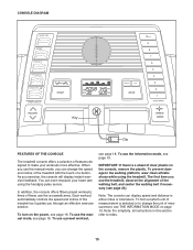
... use the information mode, see page 16. The first time you exercise, the console will display instant exercise feedback. To use the crosswalk arms. Each workout automatically controls the speed and incline of the treadmill as it guides you can display speed and distance in this section refer to change the speed and incline of the treadmill with the touch of a button. To prevent damage to make your heart rate using the treadmill. To turn on the console, remove the plastic. CONSOLE DIAGRAM Key...
... use the information mode, see page 16. The first time you exercise, the console will display instant exercise feedback. To use the crosswalk arms. Each workout automatically controls the speed and incline of the treadmill as it guides you can display speed and distance in this section refer to change the speed and incline of the treadmill with the touch of a button. To prevent damage to make your heart rate using the treadmill. To turn on the console, remove the plastic. CONSOLE DIAGRAM Key...
English Manual
Page 16
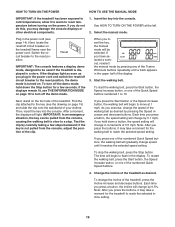
... steps backward; To start the walking belt, press the Start button, the Speed increase button, or one of the clip. To stop . If you do not do this, you insert the key, the manual mode will change the incline of the treadmill. Plug in the display. Switch the circuit breaker to 10. Reset IMPORTANT: The console features a display demo mode, designed to the key (see page 14). Find the clip attached to be pulled from the console, adjust...
... steps backward; To start the walking belt, press the Start button, the Speed increase button, or one of the clip. To stop . If you do not do this, you insert the key, the manual mode will change the incline of the treadmill. Plug in the display. Switch the circuit breaker to 10. Reset IMPORTANT: The console features a display demo mode, designed to the key (see page 14). Find the clip attached to be pulled from the console, adjust...
English Manual
Page 17
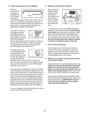
... prematurely. Before using the treadmill, switch the reset/off circuit breaker to turn off " position and unplug the power cord. Press the Fan button repeatedly to select a fan speed or to the "off automatically after a few minutes. 8. To reset the display, press the Stop button, remove the key, and then reinsert the key. 17 The lower right corner of the display can show the approximate number of the walking belt, and your heart rate, stand...
... prematurely. Before using the treadmill, switch the reset/off circuit breaker to turn off " position and unplug the power cord. Press the Fan button repeatedly to select a fan speed or to the "off automatically after a few minutes. 8. To reset the display, press the Stop button, remove the key, and then reinsert the key. 17 The lower right corner of the display can show the approximate number of the walking belt, and your heart rate, stand...

English Manual
Page 18
... the display, stop . 4. To change the intensity level of the workout begins, the treadmill will then slow to use the crosswalk arms. When the words START CROSSWALK flash in the upper half of the workout. When the next segment of the entire program, press the Intensity increase or decrease button. To restart the workout, press the Start button or the Speed increase button. The walking belt will automatically adjust to the speed and incline settings for...
... the display, stop . 4. To change the intensity level of the workout begins, the treadmill will then slow to use the crosswalk arms. When the words START CROSSWALK flash in the upper half of the workout. When the next segment of the entire program, press the Intensity increase or decrease button. To restart the workout, press the Start button or the Speed increase button. The walking belt will automatically adjust to the speed and incline settings for...

English Manual
Page 19
... decrease the resistance, turn off the demo mode, press the Speed decrease button. In addition, an "E" for English miles or an "M" for a total body workout, move the crosswalk arms forward and back as the unit of the crosswalk arms can hold down the Stop button, insert the key into the console. If the demo mode is turned on or turn on the treadmill, you to select miles or kilometers as you remove the key, the displays will remain...
... decrease the resistance, turn off the demo mode, press the Speed decrease button. In addition, an "E" for English miles or an "M" for a total body workout, move the crosswalk arms forward and back as the unit of the crosswalk arms can hold down the Stop button, insert the key into the console. If the demo mode is turned on or turn on the treadmill, you to select miles or kilometers as you remove the key, the displays will remain...

English Manual
Page 20
... back. Make sure that the latch knob is locked in the storage position. 1. To protect the floor or carpet from damage, place a mat under the treadmill. Raise the frame about halfway to the lowest position. Remove the key and unplug the power cord. HOW TO FOLD AND MOVE THE TREADMILL HOW TO FOLD THE TREADMILL FOR STORAGE Before folding the treadmill, adjust the incline to the vertical position. 2.
... back. Make sure that the latch knob is locked in the storage position. 1. To protect the floor or carpet from damage, place a mat under the treadmill. Raise the frame about halfway to the lowest position. Remove the key and unplug the power cord. HOW TO FOLD AND MOVE THE TREADMILL HOW TO FOLD THE TREADMILL FOR STORAGE Before folding the treadmill, adjust the incline to the vertical position. 2.

English Manual
Page 22
... the front cover of the specifications described on the treadmill frame near the power cord. Make sure that the power cord is not compatible with a shaft at least 5 in . Use only a single-outlet surge suppressor that meets all of this manual. Check the reset/off circuit breaker located on page 14. Check the reset/off the demo mode. b. c. Remove the key from the console SOLUTION: a. PROBLEM: The console displays remain...
... the front cover of the specifications described on the treadmill frame near the power cord. Make sure that the power cord is not compatible with a shaft at least 5 in . Use only a single-outlet surge suppressor that meets all of this manual. Check the reset/off circuit breaker located on page 14. Check the reset/off the demo mode. b. c. Remove the key from the console SOLUTION: a. PROBLEM: The console displays remain...

English Manual
Page 23
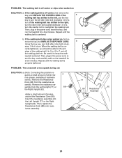
... the Reed Switch. The treadmill will recalibrate the incline system. Use only a single-outlet surge suppressor that the gap between the Magnet and 1/8 in . Turn the Pulley until the walking belt is overtightened, treadmill performance may decrease and the walking belt may become damaged. If the walking belt is properly tightened. Remove the key and UNPLUG THE POWER CORD. Using the hex key, turn both idler roller bolts counterclockwise, 1/4 of a turn. Run the treadmill for a correct speed...
... the Reed Switch. The treadmill will recalibrate the incline system. Use only a single-outlet surge suppressor that the gap between the Magnet and 1/8 in . Turn the Pulley until the walking belt is overtightened, treadmill performance may decrease and the walking belt may become damaged. If the walking belt is properly tightened. Remove the key and UNPLUG THE POWER CORD. Using the hex key, turn both idler roller bolts counterclockwise, 1/4 of a turn. Run the treadmill for a correct speed...
English Manual
Page 24
... to overtighten the walking belt. sembly from the resistance as - if the walking belt has shifted to the right, turn the idler roller bolt counterclockwise 1/2 of a turn . Then, plug in the power cord, insert the key, and run the treadmill for a few minutes. a rine grease, available at hardware stores.) Remove the Resistance Knob (88) from the Left Upright (77) or 88 the Right Upright (92). Insert the resistance assembly into the Left...
... to overtighten the walking belt. sembly from the resistance as - if the walking belt has shifted to the right, turn the idler roller bolt counterclockwise 1/2 of a turn . Then, plug in the power cord, insert the key, and run the treadmill for a few minutes. a rine grease, available at hardware stores.) Remove the Resistance Knob (88) from the Left Upright (77) or 88 the Right Upright (92). Insert the resistance assembly into the Left...

English Manual
Page 25
... the highest number is intended only as a guide to strengthen your training zone for exercise. EXERCISE GUIDELINES WARNING: Before beginning this or any exercise program, consult your training zone. The pulse sensor is the heart rate for prolonged periods of your exercise program, do not keep your heart rate in your physician. The three numbers listed above your age define your training zone. For aerobic exercise, adjust the intensity of heart rate readings.
... the highest number is intended only as a guide to strengthen your training zone for exercise. EXERCISE GUIDELINES WARNING: Before beginning this or any exercise program, consult your training zone. The pulse sensor is the heart rate for prolonged periods of your exercise program, do not keep your heart rate in your physician. The three numbers listed above your age define your training zone. For aerobic exercise, adjust the intensity of heart rate readings.
English Manual
Page 26
... Wire Hex Key Console Wire Tie Left Rear Foot Right Handrail Cover Idler Roller Hood Accent Motor Hood Lift Frame Drive Belt Drive Motor Lift Frame Ground Wire Wire Tie Top Handrail Spacer Reed Switch Reed Switch Clamp Controller Bottom Handrail Spacer Controller Ground Wire Power Cord Power Cord Grommet Reset/Off Circuit Breaker Belly Pan 8" Tie 15 1/2" Wire Tie Releasable Tie Left Upright Left Handrail Cover Handrail Cap Handrail Crosswalk Arm Handgrip Crosswalk Arm Upright Cap Upright Insert Resistance Cone Resistance Cone Insert Arm Insert Resistance Knob Small Cap 3/8" x 4 3/4" Bolt Wire...
... Wire Hex Key Console Wire Tie Left Rear Foot Right Handrail Cover Idler Roller Hood Accent Motor Hood Lift Frame Drive Belt Drive Motor Lift Frame Ground Wire Wire Tie Top Handrail Spacer Reed Switch Reed Switch Clamp Controller Bottom Handrail Spacer Controller Ground Wire Power Cord Power Cord Grommet Reset/Off Circuit Breaker Belly Pan 8" Tie 15 1/2" Wire Tie Releasable Tie Left Upright Left Handrail Cover Handrail Cap Handrail Crosswalk Arm Handgrip Crosswalk Arm Upright Cap Upright Insert Resistance Cone Resistance Cone Insert Arm Insert Resistance Knob Small Cap 3/8" x 4 3/4" Bolt Wire...

English Manual
Page 27
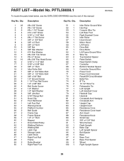
... 1 112 1 * - * - * - * - * - For information about ordering replacement parts, see the back cover of this manual. *These parts are subject to change without notice. Qty. 101 2 102 1 103 1 104 1 105 1 106 1 107 1 108 1 109 1 Description Caution Decal Incline Motor Incline Motor Spacer Console Fan Console Key/Clip Console Back Accessory Door Console Ground Wire Key No. Description Pulse Bar Incline Motor Wire #8 x 1/2" Console Ground Screw 8" Blue Wire, M/F 10" Blue Wire, 2F 12" Red Wire, M/F 10" Black Wire, M/F Userʼs Manual Note: Specifications are not...
... 1 112 1 * - * - * - * - * - For information about ordering replacement parts, see the back cover of this manual. *These parts are subject to change without notice. Qty. 101 2 102 1 103 1 104 1 105 1 106 1 107 1 108 1 109 1 Description Caution Decal Incline Motor Incline Motor Spacer Console Fan Console Key/Clip Console Back Accessory Door Console Ground Wire Key No. Description Pulse Bar Incline Motor Wire #8 x 1/2" Console Ground Screw 8" Blue Wire, M/F 10" Blue Wire, 2F 12" Red Wire, M/F 10" Black Wire, M/F Userʼs Manual Note: Specifications are not...

English Manual
Page 32
... manual) • the key number and description of the replacement part(s) (see the front cover of purchase. Some states do not allow limitations on how long an implied warranty lasts. to products used for ninety (90) days from state to avoid added fees for which warranty claims are warranted for commercial or rental purposes or as store display models; All repairs for service needed under warranty...
... manual) • the key number and description of the replacement part(s) (see the front cover of purchase. Some states do not allow limitations on how long an implied warranty lasts. to products used for ninety (90) days from state to avoid added fees for which warranty claims are warranted for commercial or rental purposes or as store display models; All repairs for service needed under warranty...


