
Uk Manual
Page 1
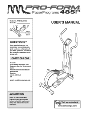
Model No. As a manufacturer, we are missing or damaged parts, please call: 08457 089 009 Or write: ICON Health & Fitness, Ltd. USER'S MANUAL Serial Number Decal QUESTIONS? Keep this equipment. PFEVEL2483.2 Serial No. Customer Service Department Unit 4 Revie Road Industrial Estate Revie Road Beeston Leeds, LS118JG UK email: [email protected] CAUTION Read all precautions and instructions in this manual before using this manual for future reference. If you have questions, or if there are committed to providing complete customer satisfaction.
Model No. As a manufacturer, we are missing or damaged parts, please call: 08457 089 009 Or write: ICON Health & Fitness, Ltd. USER'S MANUAL Serial Number Decal QUESTIONS? Keep this equipment. PFEVEL2483.2 Serial No. Customer Service Department Unit 4 Revie Road Industrial Estate Revie Road Beeston Leeds, LS118JG UK email: [email protected] CAUTION Read all precautions and instructions in this manual before using this manual for future reference. If you have questions, or if there are committed to providing complete customer satisfaction.
Uk Manual
Page 2
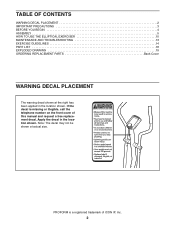
... in the location shown. If the decal is a registered trademark of this manual and request a free replacement decal. TABLE OF CONTENTS WARNING DECAL PLACEMENT 2 IMPORTANT PRECAUTIONS 3 BEFORE YOU BEGIN 4 ASSEMBLY 5 HOW TO USE THE ELLIPTICAL EXERCISER 10 MAINTENANCE AND TROUBLESHOOTING 13 EXERCISE GUIDELINES 14 PART LIST 18 EXPLODED DRAWING 19 ORDERING REPLACEMENT PARTS Back Cover WARNING DECAL PLACEMENT The warning decal shown at actual size. 246724 246723...
... in the location shown. If the decal is a registered trademark of this manual and request a free replacement decal. TABLE OF CONTENTS WARNING DECAL PLACEMENT 2 IMPORTANT PRECAUTIONS 3 BEFORE YOU BEGIN 4 ASSEMBLY 5 HOW TO USE THE ELLIPTICAL EXERCISER 10 MAINTENANCE AND TROUBLESHOOTING 13 EXERCISE GUIDELINES 14 PART LIST 18 EXPLODED DRAWING 19 ORDERING REPLACEMENT PARTS Back Cover WARNING DECAL PLACEMENT The warning decal shown at actual size. 246724 246723...
Uk Manual
Page 3
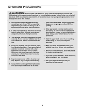
... institutional setting. 7. Use your elliptical exerciser to protect the floor or carpet. This is intended for persons over the age of all warnings on a level surface, with pre-existing health problems. 2. Your elliptical exerciser is especially important for home use it to mount, dismount, and use only. Hold the upper body arms when mounting, dismounting, or using your elliptical exerciser in this manual and all precautions. 3. ICON assumes...
... institutional setting. 7. Use your elliptical exerciser to protect the floor or carpet. This is intended for persons over the age of all warnings on a level surface, with pre-existing health problems. 2. Your elliptical exerciser is especially important for home use it to mount, dismount, and use only. Hold the upper body arms when mounting, dismounting, or using your elliptical exerciser in this manual and all precautions. 3. ICON assumes...
Uk Manual
Page 4
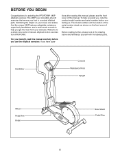
... reading this manual. Handlebar Console Resistance Knob Upright Wheel Pedal Arm Pedal Side Shield Pedal Disc 4 The model number and the location of this manual, please see the front cover of natural, elliptical-motion exercise from your exercise. Before reading further, please look at the drawing below and familiarize yourself with the labeled parts. For your knees and ankles. The 485P is an incredibly smooth exerciser that moves your feet...
... reading this manual. Handlebar Console Resistance Knob Upright Wheel Pedal Arm Pedal Side Shield Pedal Disc 4 The model number and the location of this manual, please see the front cover of natural, elliptical-motion exercise from your exercise. Before reading further, please look at the drawing below and familiarize yourself with the labeled parts. For your knees and ankles. The 485P is an incredibly smooth exerciser that moves your feet...
Uk Manual
Page 5
... Bolt (34)-4 M8 x 45mm Button Bolt (50)-4 Pedal Arm Bolt Set (40)-2 1. In addition to identify the small parts used in assembly. Make sure that the Front Stabilizer is completed. While another person lifts the front of the Frame (1), attach the Front Stabilizer to see if it has been preattached. ASSEMBLY Assembly requires two persons. Place all parts of pliers . , two adjustable Use the chart below each part...
... Bolt (34)-4 M8 x 45mm Button Bolt (50)-4 Pedal Arm Bolt Set (40)-2 1. In addition to identify the small parts used in assembly. Make sure that the Front Stabilizer is completed. While another person lifts the front of the Frame (1), attach the Front Stabilizer to see if it has been preattached. ASSEMBLY Assembly requires two persons. Place all parts of pliers . , two adjustable Use the chart below each part...

Uk Manual
Page 6
... the tip of the Resistance Cable (45) into the metal bracket on the Lower Resistance Cable (65) as shown. • See drawing C. Attach the Upright with two M10 x 75mm Carriage Bolts (34) and two M10 Nylon Locknuts (33). 33 1 33 9 34 3. Slide the Upright (2) onto the Frame (1); Do not tighten the Button Bolts yet. 3 2 Make sure not to the Reed Switch Wire (53). While another...
... the tip of the Resistance Cable (45) into the metal bracket on the Lower Resistance Cable (65) as shown. • See drawing C. Attach the Upright with two M10 x 75mm Carriage Bolts (34) and two M10 Nylon Locknuts (33). 33 1 33 9 34 3. Slide the Upright (2) onto the Frame (1); Do not tighten the Button Bolts yet. 3 2 Make sure not to the Reed Switch Wire (53). While another...

Uk Manual
Page 7
... into one of the Handlebar Arms with four M4 x 12mm Screws (42). Next, attach the Console to one of the hexagonal holes. 4. Connect the Upper Wire (44) to the other Handlebar Arm (not shown) in the same way. 6 38 50 5 Hexagonal Holes 7 Do not fully tighten the Button Bolts yet. Press the Resistance Knob (63) onto the Resistance Control (45). 4 Console Wire 42 44 2 63 23 45...
... into one of the Handlebar Arms with four M4 x 12mm Screws (42). Next, attach the Console to one of the hexagonal holes. 4. Connect the Upper Wire (44) to the other Handlebar Arm (not shown) in the same way. 6 38 50 5 Hexagonal Holes 7 Do not fully tighten the Button Bolts yet. Press the Resistance Knob (63) onto the Resistance Control (45). 4 Console Wire 42 44 2 63 23 45...
Uk Manual
Page 8
...Insert the left 7 Disc Crossbar (16). Tighten the M8 x 45mm Button Bolts (50) in the Handlebar Arms (5). Tighten the two M10 x 76mm Button Bolts (67). 5 40 11 67 5 38 35 16 Grease 8 6. Apply a generous amount of the Left Pedal Arm (11), and attach it . Repeat this step to the axle on the correct sides. ... Caps (46) 46 as shown, and press the small tabs on 8 Grease each end of the Pivot Axle. Slide a Handlebar Spacer (47) onto the short tube on the Handlebar Caps into the Upright (2) and center it with a Pedal Arm Bolt Set (40). Make sure that the Handlebars are...
...Insert the left 7 Disc Crossbar (16). Tighten the M8 x 45mm Button Bolts (50) in the Handlebar Arms (5). Tighten the two M10 x 76mm Button Bolts (67). 5 40 11 67 5 38 35 16 Grease 8 6. Apply a generous amount of the Left Pedal Arm (11), and attach it . Repeat this step to the axle on the correct sides. ... Caps (46) 46 as shown, and press the small tabs on 8 Grease each end of the Pivot Axle. Slide a Handlebar Spacer (47) onto the short tube on the Handlebar Caps into the Upright (2) and center it with a Pedal Arm Bolt Set (40). Make sure that the Handlebars are...
Uk Manual
Page 9
... of the elliptical exerciser are recommended. Attach the Left Pedal to the Left Pedal Arm 8 (11) with three M4 x 19mm Flange Screws (36) as shown. 13 Attach the Right Pedal to protect the floor or carpet from damage. 9 The Console (23) requires three 1.5V "AAA" batteries; 9 alkaline batteries are properly tightened. Slide off the Battery Cover (29) and press the batteries into the battery clip; Reattach the Battery Cover. 36...
... of the elliptical exerciser are recommended. Attach the Left Pedal to the Left Pedal Arm 8 (11) with three M4 x 19mm Flange Screws (36) as shown. 13 Attach the Right Pedal to protect the floor or carpet from damage. 9 The Console (23) requires three 1.5V "AAA" batteries; 9 alkaline batteries are properly tightened. Slide off the Battery Cover (29) and press the batteries into the battery clip; Reattach the Battery Cover. 36...
Uk Manual
Page 10
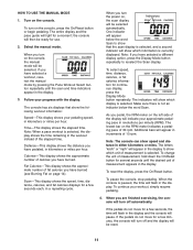
... installed (see assembly step 9 on page 11. As you through an effective workout. CAUTION: The elliptical exerciser does not have a free wheel; wise. Important: The knob may choose to move until they begin to turn the pedal discs in the opposite direction. The console also offers four pace workouts that prompt you may not stop turning it or damage will provide continuous exercise feedback. To Knob increase the resistance, turn , stop turning...
... installed (see assembly step 9 on page 11. As you through an effective workout. CAUTION: The elliptical exerciser does not have a free wheel; wise. Important: The knob may choose to move until they begin to turn the pedal discs in the opposite direction. The console also offers four pace workouts that prompt you may not stop turning it or damage will provide continuous exercise feedback. To Knob increase the resistance, turn , stop turning...
Uk Manual
Page 11
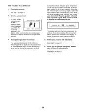
... reset. ? If the pedals do not move for use. 2. When you have selected a different display option, press the Display Mode button repeatedly to show that show speed and distance in increments of calories you pedal, the RPM meter on the console. If you turn off automatically. Note: When a pace workout is paused, the time will turn on the console, press the On/Reset button or begin pedaling. Scan-This display shows the speed...
... reset. ? If the pedals do not move for use. 2. When you have selected a different display option, press the Display Mode button repeatedly to show that show speed and distance in increments of calories you pedal, the RPM meter on the console. If you turn off automatically. Note: When a pace workout is paused, the time will turn on the console, press the On/Reset button or begin pedaling. Scan-This display shows the speed...
Uk Manual
Page 12
... you stop pedaling, the workout will pause and the time will flash in the display. To restart the workout, simply resume pedaling. 4. To select a pace workout, press the Pace Workout Select button repeatedly until P1, P2, P3, or P4 appears in the display. A few seconds after you are finished exercising, the console will show the time remaining in the workout. Note: You can set the resistance...
... you stop pedaling, the workout will pause and the time will flash in the display. To restart the workout, simply resume pedaling. 4. To select a pace workout, press the Pace Workout Select button repeatedly until P1, P2, P3, or P4 appears in the display. A few seconds after you are finished exercising, the console will show the time remaining in the workout. Note: You can set the resistance...
Uk Manual
Page 13
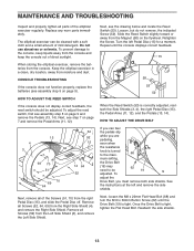
... the console does not function properly, replace the batteries (see assembly step 8 on page 9). Remove all parts of mild detergent. Retighten the Screw. Turn the left and remove the side shields. See the instructions at the left Pedal Disc (15) for a moment. MAINTENANCE AND TROUBLESHOOTING Inspect and properly tighten all Screws (52) from the Left Side Shield (3), and remove the Left Side Shield. The elliptical exerciser can feel the pedals slip...
... the console does not function properly, replace the batteries (see assembly step 8 on page 9). Remove all parts of mild detergent. Retighten the Screw. Turn the left and remove the side shields. See the instructions at the left Pedal Disc (15) for a moment. MAINTENANCE AND TROUBLESHOOTING Inspect and properly tighten all Screws (52) from the Left Side Shield (3), and remove the Left Side Shield. The elliptical exerciser can feel the pedals slip...
Uk Manual
Page 14
... body begin to use your age at the proper intensity is not a medical device. For maximum fat burning, exercise with 5 to five workouts each week, with your heart rate in your cardiovascular system, exercising at the bottom of exercise, your breath. For detailed exercise information, obtain a reputable book or consult your training zone. A warm-up -Start with pre-existing health problems. The pulse sensor is the key...
... body begin to use your age at the proper intensity is not a medical device. For maximum fat burning, exercise with 5 to five workouts each week, with your heart rate in your cardiovascular system, exercising at the bottom of exercise, your breath. For detailed exercise information, obtain a reputable book or consult your training zone. A warm-up -Start with pre-existing health problems. The pulse sensor is the key...

Uk Manual
Page 15
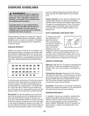
... leg in front of the other hand. Bend your front leg, lean forward and move your hands against a wall. Stretches: Calves, achilles tendons and ankles. 4. Repeat 3 times for each leg. Move ... on 3 the floor. Keep your back leg straight and your other , reach forward and place your hips toward your extended leg. Stretches: Hamstrings, lower back and groin. 3. Quadriceps Stretch With ...as you stretch-never bounce. 1. Hold for each leg. Repeat 3 times for 15 counts, then relax. SUGGESTED STRETCHES The correct form for 15 counts, then relax. Hold for several...
... leg in front of the other hand. Bend your front leg, lean forward and move your hands against a wall. Stretches: Calves, achilles tendons and ankles. 4. Repeat 3 times for each leg. Move ... on 3 the floor. Keep your back leg straight and your other , reach forward and place your hips toward your extended leg. Stretches: Hamstrings, lower back and groin. 3. Quadriceps Stretch With ...as you stretch-never bounce. 1. Hold for each leg. Repeat 3 times for 15 counts, then relax. SUGGESTED STRETCHES The correct form for 15 counts, then relax. Hold for several...
Uk Manual
Page 18
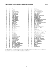
... Flange Screw 37 4 Pedal Arm Bushing 38 7 M8 Nylon Locknut 39 2 M10 Washer 40 2 Pedal Arm Bolt Set 41 2 M6 x 72mm Button Bolt 42 5 M4 x 12mm Screw 43 2 Wave Washer 44 1 Upper Wire 45 1 Resistance Control/Cable 46 2 Handlebar Cap 47 2 Handlebar Spacer 48 2 Frame Spacer 49 6 Small Handlebar Arm Bushing 50 4 M8 x 45mm Button Bolt 51 4 M6 x 25mm Screw 52 9 M4 x 16mm Self-tapping Screw 53 1 Reed Switch/Wire 54 2 Cable Clamp...
... Flange Screw 37 4 Pedal Arm Bushing 38 7 M8 Nylon Locknut 39 2 M10 Washer 40 2 Pedal Arm Bolt Set 41 2 M6 x 72mm Button Bolt 42 5 M4 x 12mm Screw 43 2 Wave Washer 44 1 Upper Wire 45 1 Resistance Control/Cable 46 2 Handlebar Cap 47 2 Handlebar Spacer 48 2 Frame Spacer 49 6 Small Handlebar Arm Bushing 50 4 M8 x 45mm Button Bolt 51 4 M6 x 25mm Screw 52 9 M4 x 16mm Self-tapping Screw 53 1 Reed Switch/Wire 54 2 Cable Clamp...
Uk Manual
Page 19
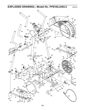
EXPLODED DRAWING-Model No. PFEVEL2483.2 R0507A 24 8 64 52 52 69 29 23 52 63 4 66 42 24 55 43 45 46 56 69 52 66 42 49 3 49 47 48 50 52 64 44 42 42 6 49 47 48 49 72 72 38 49 14 40 55 43 49 56 38 50 46 71 2 59 33 65 59 5 40 67 60 60 17 12 35 38 51 37 36 37 5 22 60 41 21 13 40 22 66 34 70 51 41 21 10 52 33 54 53 61 58 57 39 33 33 39 27 26 27 28 68 54 42 7 25 3832 30 31 31 30 33 1 62 16 33 16 61 9 34 36 70 15 51 70 18 52 20 51 37 70 15 20 19 11 40 36 37 38 35 19
EXPLODED DRAWING-Model No. PFEVEL2483.2 R0507A 24 8 64 52 52 69 29 23 52 63 4 66 42 24 55 43 45 46 56 69 52 66 42 49 3 49 47 48 50 52 64 44 42 42 6 49 47 48 49 72 72 38 49 14 40 55 43 49 56 38 50 46 71 2 59 33 65 59 5 40 67 60 60 17 12 35 38 51 37 36 37 5 22 60 41 21 13 40 22 66 34 70 51 41 21 10 52 33 54 53 61 58 57 39 33 33 39 27 26 27 28 68 54 42 7 25 3832 30 31 31 30 33 1 62 16 33 16 61 9 34 36 70 15 51 70 18 52 20 51 37 70 15 20 19 11 40 36 37 38 35 19
Uk Manual
Page 20
ORDERING REPLACEMENT PARTS To order replacement parts, see the PART LIST and EXPLODED DRAWING near the end of this manual) Part No. 256311 R0507A Printed in China © 2007 ICON IP, Inc. To help us assist you, please be prepared to provide the following information when contacting us: • the model number and serial number of the product (see the front cover of this manual) • the name of the product (see the front cover of this manual) • the key number and description of the replacement part(s) (see the front cover of this manual.
ORDERING REPLACEMENT PARTS To order replacement parts, see the PART LIST and EXPLODED DRAWING near the end of this manual) Part No. 256311 R0507A Printed in China © 2007 ICON IP, Inc. To help us assist you, please be prepared to provide the following information when contacting us: • the model number and serial number of the product (see the front cover of this manual) • the name of the product (see the front cover of this manual) • the key number and description of the replacement part(s) (see the front cover of this manual.

