
Canadian English Manual
Page 1
Model No. 30331.1 Serial No. CALL TOLL-FREE: 1-888-936-4266 Mon.-Fri., 7:30 until 16:30 ET (excluding holidays) OR E-MAIL US: [email protected] CAUTION Read all precautions and instructions in the space above for future reference. Keep this equipment. USERʼS MANUAL www.proform.com Write the serial number in this manual before using this manual for reference. Serial Number Decal QUESTIONS? If you have questions, or if parts are damaged or missing, PLEASE CONTACT OUR CUSTOMER SERVICE DEPARTMENT DIRECTLY.
Model No. 30331.1 Serial No. CALL TOLL-FREE: 1-888-936-4266 Mon.-Fri., 7:30 until 16:30 ET (excluding holidays) OR E-MAIL US: [email protected] CAUTION Read all precautions and instructions in the space above for future reference. Keep this equipment. USERʼS MANUAL www.proform.com Write the serial number in this manual before using this manual for reference. Serial Number Decal QUESTIONS? If you have questions, or if parts are damaged or missing, PLEASE CONTACT OUR CUSTOMER SERVICE DEPARTMENT DIRECTLY.
Canadian English Manual
Page 2
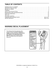
... PRECAUTIONS 3 BEFORE YOU BEGIN 4 ASSEMBLY 5 HOW TO USE THE ELLIPTICAL 15 MAINTENANCE AND TROUBLESHOOTING 20 EXERCISE GUIDELINES 22 PART LIST 24 EXPLODED DRAWING 26 ORDERING REPLACEMENT PARTS Back Cover LIMITED WARRANTY Back Cover WARNING DECAL PLACEMENT This drawing shows the location(s) of this manual and request a free replacement decal. If a decal is a registered trademark of ICON IP, Inc. 2 Apply the decal in the location shown. PROFORM is missing or illegible, see...
... PRECAUTIONS 3 BEFORE YOU BEGIN 4 ASSEMBLY 5 HOW TO USE THE ELLIPTICAL 15 MAINTENANCE AND TROUBLESHOOTING 20 EXERCISE GUIDELINES 22 PART LIST 24 EXPLODED DRAWING 26 ORDERING REPLACEMENT PARTS Back Cover LIMITED WARRANTY Back Cover WARNING DECAL PLACEMENT This drawing shows the location(s) of this manual and request a free replacement decal. If a decal is a registered trademark of ICON IP, Inc. 2 Apply the decal in the location shown. PROFORM is missing or illegible, see...
Canadian English Manual
Page 3
... that all users of the elliptical are adequately informed of all precautions. 11. Over exercising may affect the accuracy of heart rate readings. Before beginning any worn parts immediately. 8. This is especially important for home use the elliptical in a commercial, rental, or institutional setting. 5. Wear appropriate clothes while exercising; The elliptical is the responsibility of the owner to move until the flywheel stops. Replace any exercise program, consult your...
... that all users of the elliptical are adequately informed of all precautions. 11. Over exercising may affect the accuracy of heart rate readings. Before beginning any worn parts immediately. 8. This is especially important for home use the elliptical in a commercial, rental, or institutional setting. 5. Wear appropriate clothes while exercising; The elliptical is the responsibility of the owner to move until the flywheel stops. Replace any exercise program, consult your...
Canadian English Manual
Page 4
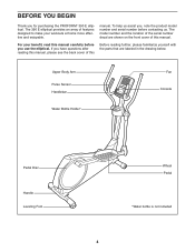
The model number and the location of the serial number decal are labeled in the drawing below. Upper Body Arm Pulse Sensor Handlebar Water Bottle Holder* Fan Console Pedal Disc Handle Leveling Foot Wheel Pedal *Water bottle is not included 4 To help us . The 390 E elliptical provides an array of this manual carefully before contacting us assist you for purchasing the PROFORM® 390 E elliptical. For your workouts at home more...
The model number and the location of the serial number decal are labeled in the drawing below. Upper Body Arm Pulse Sensor Handlebar Water Bottle Holder* Fan Console Pedal Disc Handle Leveling Foot Wheel Pedal *Water bottle is not included 4 To help us . The 390 E elliptical provides an array of this manual carefully before contacting us assist you for purchasing the PROFORM® 390 E elliptical. For your workouts at home more...
Canadian English Manual
Page 5
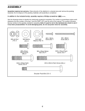
... use power tools for assembly. In addition to identify the small parts needed for assembly. M8 Jam Nut (77)-4 M8 Washer (33)-2 M10 Split Washer (78)-10 M4 x 16mm Screw (92)-7 M4 x 48mm Screw (89)-2 M8 x 20mm Patch Screw (80)-2 M8 x 45mm Button Bolt (76)-4 M10 x 20mm Patch Screw (79)-7 M10 x 48mm Patch Screw (75)-6 M10 x 85mm Patch Screw (82)-4 Shoulder Patch Bolt (31)-2 5 The number...
... use power tools for assembly. In addition to identify the small parts needed for assembly. M8 Jam Nut (77)-4 M8 Washer (33)-2 M10 Split Washer (78)-10 M4 x 16mm Screw (92)-7 M4 x 48mm Screw (89)-2 M8 x 20mm Patch Screw (80)-2 M8 x 45mm Button Bolt (76)-4 M10 x 20mm Patch Screw (79)-7 M10 x 48mm Patch Screw (75)-6 M10 x 85mm Patch Screw (82)-4 Shoulder Patch Bolt (31)-2 5 The number...
Canadian English Manual
Page 8
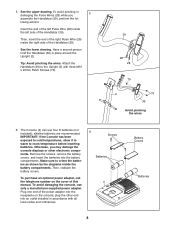
... the cover of the power adapter into the battery compartments. To purchase an optional power adapter, call the telephone number on the console; Tip: Avoid pinching the wires. The Console (4) can use only a manufacturer-supplied power adapter. Then, reattach the battery covers. Plug one end of this manual. See the lower drawing. Make sure to orient the batteries as shown by the diagrams inside the left Pulse Wire (28) inside the battery compartments...
... the cover of the power adapter into the battery compartments. To purchase an optional power adapter, call the telephone number on the console; Tip: Avoid pinching the wires. The Console (4) can use only a manufacturer-supplied power adapter. Then, reattach the battery covers. Plug one end of this manual. See the lower drawing. Make sure to orient the batteries as shown by the diagrams inside the left Pulse Wire (28) inside the battery compartments...

Canadian English Manual
Page 11
... of 76 the Right Pedal Arm (49) inside the bracket on the right Upper Body Leg (6). 6 Repeat this step to attach the Left Pedal Arm (not shown) to the left Upper Body Leg (6). Attach each Upper Body Arm (8, 9) with an M8 x 20mm Patch Screw (80) and an M8 Washer (33). 10 8 80 33 2 Grease 9 33 80 11. 10. Tighten the Shoulder Patch Bolt (31) into the welded...
... of 76 the Right Pedal Arm (49) inside the bracket on the right Upper Body Leg (6). 6 Repeat this step to attach the Left Pedal Arm (not shown) to the left Upper Body Leg (6). Attach each Upper Body Arm (8, 9) with an M8 x 20mm Patch Screw (80) and an M8 Washer (33). 10 8 80 33 2 Grease 9 33 80 11. 10. Tighten the Shoulder Patch Bolt (31) into the welded...
Canadian English Manual
Page 12
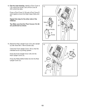
... Hooks 22 19 19 Hooks 13. Press the Water Bottle Holder (5) into the Rear Upright Cover (3). Tip: Make sure that the indicated arrow is pointing upward. Press the Front Upright Cover (16) into the Rear Upright Cover (3). 5 16 92 Arrow 2 92 3 12 Press a Pivot Cover A (19) and a Pivot Cover B (22) together around the Right Upper Body Arm (9). Repeat this step for the other side of the elliptical.
... Hooks 22 19 19 Hooks 13. Press the Water Bottle Holder (5) into the Rear Upright Cover (3). Tip: Make sure that the indicated arrow is pointing upward. Press the Front Upright Cover (16) into the Rear Upright Cover (3). 5 16 92 Arrow 2 92 3 12 Press a Pivot Cover A (19) and a Pivot Cover B (22) together around the Right Upper Body Arm (9). Repeat this step for the other side of the elliptical.
Canadian English Manual
Page 13
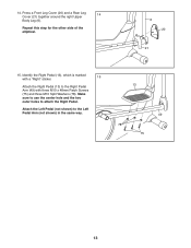
Attach the Left Pedal (not shown) to the Right Pedal Arm (49) with three M10 x 48mm Patch Screws (75) and three M10 Split Washers (78). Identify the Right Pedal (13), which is marked with a "Right" sticker. 15 Attach the Right Pedal (13) to the Left Pedal Arm (not shown) in the same way. 13 49 78 75 13 Press a Front Leg Cover (20) and a Rear Leg Cover (21) together around the right Upper 14 Body Leg (6). 14. Repeat this step for the other side of the elliptical. 6 20 21 15. Make sure to use the center hole and the two outer holes to attach the Right Pedal.
Attach the Left Pedal (not shown) to the Right Pedal Arm (49) with three M10 x 48mm Patch Screws (75) and three M10 Split Washers (78). Identify the Right Pedal (13), which is marked with a "Right" sticker. 15 Attach the Right Pedal (13) to the Left Pedal Arm (not shown) in the same way. 13 49 78 75 13 Press a Front Leg Cover (20) and a Rear Leg Cover (21) together around the right Upper 14 Body Leg (6). 14. Repeat this step for the other side of the elliptical. 6 20 21 15. Make sure to use the center hole and the two outer holes to attach the Right Pedal.
Canadian English Manual
Page 15
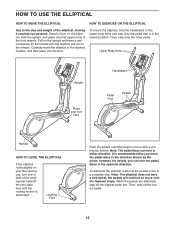
... move the elliptical to the desired location, and then lower it requires two persons. Then, step off the highest pedal first. It is eliminated. When the pedals are stationary, step off the lowest pedal. 15 Stand in front of the elliptical, hold the handlebars or the upper body arms and step onto the pedal that you can turn the pedal discs in either direction. Note: The elliptical does...
... move the elliptical to the desired location, and then lower it requires two persons. Then, step off the highest pedal first. It is eliminated. When the pedals are stationary, step off the lowest pedal. 15 Stand in front of the elliptical, hold the handlebars or the upper body arms and step onto the pedal that you can turn the pedal discs in either direction. Note: The elliptical does...
Canadian English Manual
Page 16
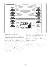
... you exercise, the console will provide continuous exercise feedback. As you exercise. The console offers twelve preset workouts-seven weight loss workouts and five performance workouts. To use a preset workout, see page 17. CONSOLE DIAGRAM FEATURES OF THE CONSOLE The advanced console offers an array of the pedals as it guides you through an effective workout. Each preset workout automatically changes the resistance of features designed to your heart rate using the console, make your workouts...
... you exercise, the console will provide continuous exercise feedback. As you exercise. The console offers twelve preset workouts-seven weight loss workouts and five performance workouts. To use a preset workout, see page 17. CONSOLE DIAGRAM FEATURES OF THE CONSOLE The advanced console offers an array of the pedals as it guides you through an effective workout. Each preset workout automatically changes the resistance of features designed to your heart rate using the console, make your workouts...
Canadian English Manual
Page 17
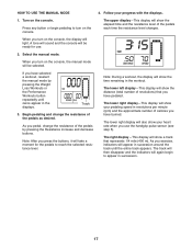
... a workout, reselect the manual mode by pressing the Resistance increase and decrease buttons. The upper display-This display will take a moment for use the handgrip pulse sensor (see step 5). Select the manual mode. A tone will sound and the console will light. Track 3. Note: During a workout, the display will show a track that you turn on the console, the manual mode will appear in succession around the track until zeros appear in the workout. As you exercise, indicators...
... a workout, reselect the manual mode by pressing the Resistance increase and decrease buttons. The upper display-This display will take a moment for use the handgrip pulse sensor (see step 5). Select the manual mode. A tone will sound and the console will light. Track 3. Note: During a workout, the display will show a track that you turn on the console, the manual mode will appear in succession around the track until zeros appear in the workout. As you exercise, indicators...
Canadian English Manual
Page 18
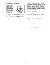
... exercising, the console will be shown. If there are positioned as described. To measure your heart rate is detected, a heart-shaped symbol will flash in the display. The fan has high and low speed settings. When you are clean. If the pedals do not move for at least 15 seconds. Measure your hands or gripping the con- Turn on the handgrip pulse sensor, remove...
... exercising, the console will be shown. If there are positioned as described. To measure your heart rate is detected, a heart-shaped symbol will flash in the display. The fan has high and low speed settings. When you are clean. If the pedals do not move for at least 15 seconds. Measure your hands or gripping the con- Turn on the handgrip pulse sensor, remove...

Canadian English Manual
Page 19
... you exercise, plug the audio cable into the jack on your progress (see the drawing above). See step 5 on page 18. 7. See step 6 on page 18. 6. Adjust the volume level using the volume control on the fan if desired. Follow your heart rate if desired. Turn on your MP3 player or CD player. Begin pedaling to the resistance level for several seconds, a series of the workout...
... you exercise, plug the audio cable into the jack on your progress (see the drawing above). See step 5 on page 18. 7. See step 6 on page 18. 6. Adjust the volume level using the volume control on the fan if desired. Follow your heart rate if desired. Turn on your MP3 player or CD player. Begin pedaling to the resistance level for several seconds, a series of the workout...
Canadian English Manual
Page 20
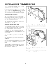
... pulse sensor does not function properly, see step 5 on page 14 and remove the rear shield cover. Next, loosen the Pivot Screw (88). MAINTENANCE AND TROUBLESHOOTING Inspect and tighten all the batteries at the same time; most console problems are pedaling, even when the resistance is adjusted to the highest level, the drive belt may need to the console, keep the console out of direct sunlight. 14 CONSOLE TROUBLESHOOTING If the console displays become dim, replace all parts...
... pulse sensor does not function properly, see step 5 on page 14 and remove the rear shield cover. Next, loosen the Pivot Screw (88). MAINTENANCE AND TROUBLESHOOTING Inspect and tighten all the batteries at the same time; most console problems are pedaling, even when the resistance is adjusted to the highest level, the drive belt may need to the console, keep the console out of direct sunlight. 14 CONSOLE TROUBLESHOOTING If the console displays become dim, replace all parts...
Canadian English Manual
Page 21
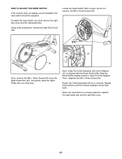
..., remove the M8 x 12mm Screws (81) from the Magnet. Rotate the Crank Assembly (24) for a moment. Repeat these actions until a Magnet (41) is correctly adjusted, reattach the right pedal disc and the right disc cover. 21 Next, rotate the Crank Assembly (24) until the console displays correct feedback. HOW TO ADJUST THE REED SWITCH If the console does not display correct feedback, the reed switch should be adjusted. When...
..., remove the M8 x 12mm Screws (81) from the Magnet. Rotate the Crank Assembly (24) for a moment. Repeat these actions until a Magnet (41) is correctly adjusted, reattach the right pedal disc and the right disc cover. 21 Next, rotate the Crank Assembly (24) until the console displays correct feedback. HOW TO ADJUST THE REED SWITCH If the console does not display correct feedback, the reed switch should be adjusted. When...
Canadian English Manual
Page 22
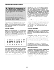
... pre-existing health problems. The pulse sensor is near the middle number in general. Training Zone Exercise-Exercise for longer than 20 minutes.) Breathe regularly and deeply as a guide to make exercise a regular and enjoyable part of your cardiovascular system, you to 30 minutes with 5 to burn fat, adjust the intensity of heart rate readings. EXERCISE GUIDELINES WARNING: Before beginning this or any exercise program, consult your...
... pre-existing health problems. The pulse sensor is near the middle number in general. Training Zone Exercise-Exercise for longer than 20 minutes.) Breathe regularly and deeply as a guide to make exercise a regular and enjoyable part of your cardiovascular system, you to 30 minutes with 5 to burn fat, adjust the intensity of heart rate readings. EXERCISE GUIDELINES WARNING: Before beginning this or any exercise program, consult your...
Canadian English Manual
Page 24
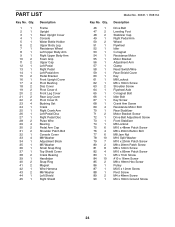
... 10 85 2 86 1 87 1 88 1 89 2 90 1 Model No. 30331.1 R0811A Description Drive Belt Leveling Foot Stabilizer Cap Right Pedal Arm Wheel Flywheel Idler C-magnet Resistance Motor Motor Bracket Adjustment Arm Clamp Reed Switch/Wire Rear Shield Cover Key M8 Locknut M6 x 16mm Screw Shoulder Screw Flywheel Axle C-magnet Bolt Idler Bolt Key Screw Crank Arm Screw Resistance Motor Bolt Rear Stabilizer Motor Bracket Screw Drive Belt Adjustment Screw Front Stabilizer M6 Locknut M10 x 48mm Patch Screw M8 x 45mm Button Bolt M8 Jam Nut M10 Split Washer M10...
... 10 85 2 86 1 87 1 88 1 89 2 90 1 Model No. 30331.1 R0811A Description Drive Belt Leveling Foot Stabilizer Cap Right Pedal Arm Wheel Flywheel Idler C-magnet Resistance Motor Motor Bracket Adjustment Arm Clamp Reed Switch/Wire Rear Shield Cover Key M8 Locknut M6 x 16mm Screw Shoulder Screw Flywheel Axle C-magnet Bolt Idler Bolt Key Screw Crank Arm Screw Resistance Motor Bolt Rear Stabilizer Motor Bracket Screw Drive Belt Adjustment Screw Front Stabilizer M6 Locknut M10 x 48mm Patch Screw M8 x 45mm Button Bolt M8 Jam Nut M10 Split Washer M10...

Canadian English Manual
Page 25
Qty. Description 91 2 Adjustment Nut 92 21 M4 x 16mm Screw 93 2 Pulse Sensor/Wire 94 1 Flywheel Bearing 95 1 Audio Cable 96 1 Left Crank Arm 97 1 Crank Arm Spacer 98 4 M8 x 10mm Screw 99 4 M8 x 15mm Screw * - Wire Tie Note: Specifications are not illustrated. 25 Userʼs Manual * - Key No. Description Key No. Grease Packet * - For information about ordering replacement parts, see the back cover of this manual. *These parts are subject to change without notice. Assembly Tool * - Qty.
Qty. Description 91 2 Adjustment Nut 92 21 M4 x 16mm Screw 93 2 Pulse Sensor/Wire 94 1 Flywheel Bearing 95 1 Audio Cable 96 1 Left Crank Arm 97 1 Crank Arm Spacer 98 4 M8 x 10mm Screw 99 4 M8 x 15mm Screw * - Wire Tie Note: Specifications are not illustrated. 25 Userʼs Manual * - Key No. Description Key No. Grease Packet * - For information about ordering replacement parts, see the back cover of this manual. *These parts are subject to change without notice. Assembly Tool * - Qty.
Canadian English Manual
Page 28
...; the model number and serial number of the product (see the front cover of this manual) • the name of the product (see the front cover of this manual) • the key number and description of the replacement part(s) (see the front cover of this warranty is limited to repairing or replacing, at ICONʼs option, the product through one of its authorized service centers. or products used for five...
...; the model number and serial number of the product (see the front cover of this manual) • the name of the product (see the front cover of this manual) • the key number and description of the replacement part(s) (see the front cover of this warranty is limited to repairing or replacing, at ICONʼs option, the product through one of its authorized service centers. or products used for five...


