
English Manual
Page 1
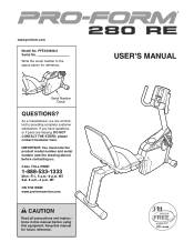
... us: CALL TOLL-FREE: 1-888-533-1333 Mon.-Fri., 6 a.m.-6 p.m. MT ON THE WEB: www.proformservice.com CAUTION Read all precautions and instructions in the space above ) before using this manual for reference. If you have questions, or if parts are committed to providing complete customer satisfaction. USER'S MANUAL IMPORTANT: You must note the product model number and serial number (see the drawing...
... us: CALL TOLL-FREE: 1-888-533-1333 Mon.-Fri., 6 a.m.-6 p.m. MT ON THE WEB: www.proformservice.com CAUTION Read all precautions and instructions in the space above ) before using this manual for reference. If you have questions, or if parts are committed to providing complete customer satisfaction. USER'S MANUAL IMPORTANT: You must note the product model number and serial number (see the drawing...
English Manual
Page 2
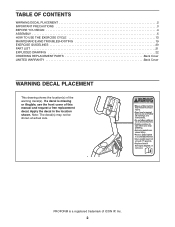
... YOU BEGIN 4 ASSEMBLY 5 HOW TO USE THE EXERCISE CYCLE 13 MAINTENANCE AND TROUBLESHOOTING 19 EXERCISE GUIDELINES 20 PART LIST 21 EXPLODED DRAWING 22 ORDERING REPLACEMENT PARTS Back Cover LIMITED WARRANTY Back Cover WARNING DECAL PLACEMENT This drawing shows the location(s) of ICON IP, Inc. 2 Note: The decal(s) may not be shown at actual size. PROFORM is missing or illegible, see the front cover of this manual and request a free replacement decal. If...
... YOU BEGIN 4 ASSEMBLY 5 HOW TO USE THE EXERCISE CYCLE 13 MAINTENANCE AND TROUBLESHOOTING 19 EXERCISE GUIDELINES 20 PART LIST 21 EXPLODED DRAWING 22 ORDERING REPLACEMENT PARTS Back Cover LIMITED WARRANTY Back Cover WARNING DECAL PLACEMENT This drawing shows the location(s) of ICON IP, Inc. 2 Note: The decal(s) may not be shown at actual size. PROFORM is missing or illegible, see the front cover of this manual and request a free replacement decal. If...
English Manual
Page 3
... the responsibility of the owner to a stop immediately and cool down. 13. Keep your back straight while using your exercise cycle. Do not use of this product. 1. The pulse sensor is at all times. 10. Inspect and properly tighten all parts regularly. Replace any exercise program, consult your exercise cycle in a commercial, rental, or institutional setting. 8. Your exercise cycle should not be used by or through...
... the responsibility of the owner to a stop immediately and cool down. 13. Keep your back straight while using your exercise cycle. Do not use of this product. 1. The pulse sensor is at all times. 10. Inspect and properly tighten all parts regularly. Replace any exercise program, consult your exercise cycle in a commercial, rental, or institutional setting. 8. Your exercise cycle should not be used by or through...
English Manual
Page 4
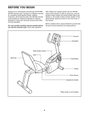
... for increasing cardiovascular fitness, building endurance, and toning the body. Cycling is not included 4 If you have questions after reading this manual, please see the FRONT cover of this manual. Console Handlebar Backrest Water Bottle Holder* Seat Pedal/Strap Wheel Pulse Sensor Adjustment Handle *Water bottle is an effective exercise for selecting the revolutionary PROFORM® 280 RE exercise cycle. For your workouts at home more effective and...
... for increasing cardiovascular fitness, building endurance, and toning the body. Cycling is not included 4 If you have questions after reading this manual, please see the FRONT cover of this manual. Console Handlebar Backrest Water Bottle Holder* Seat Pedal/Strap Wheel Pulse Sensor Adjustment Handle *Water bottle is an effective exercise for selecting the revolutionary PROFORM® 280 RE exercise cycle. For your workouts at home more effective and...
English Manual
Page 5
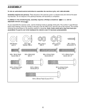
...-2480. Do not dispose of the packing materials until assembly is the quantity needed for assembly. Note: Some small parts may have been preassembled. If a part is the key number of the part, from the PART LIST near the end of the exercise cycle in a cleared area and remove the packing materials. The number following the parentheses is completed. and an As you...
...-2480. Do not dispose of the packing materials until assembly is the quantity needed for assembly. Note: Some small parts may have been preassembled. If a part is the key number of the part, from the PART LIST near the end of the exercise cycle in a cleared area and remove the packing materials. The number following the parentheses is completed. and an As you...

English Manual
Page 6
Attach the Front Stabilizer (3) to the Frame (1) with three M10 x 64mm Patch Screws (52). 2 52 1 2 6 Have the other person hold the Frame to prevent it from moving from side to the Frame (1) with two M10 x 80mm Patch Screws (47) and two M10 Split Washers (48). 3 1 48 47 2. 1. Attach the Rear Stabilizer (2) to side until you begin. To make assembly easier, read the 1 information on page 5 before you complete this step. With the help of another person, lift the Frame (1) and place a packing insert (not shown) under the Frame.
Attach the Front Stabilizer (3) to the Frame (1) with three M10 x 64mm Patch Screws (52). 2 52 1 2 6 Have the other person hold the Frame to prevent it from moving from side to the Frame (1) with two M10 x 80mm Patch Screws (47) and two M10 Split Washers (48). 3 1 48 47 2. 1. Attach the Rear Stabilizer (2) to side until you begin. To make assembly easier, read the 1 information on page 5 before you complete this step. With the help of another person, lift the Frame (1) and place a packing insert (not shown) under the Frame.

English Manual
Page 9
... where you may damage the console displays or other end into the battery compartments, and reattach the battery cover. Attach the Console (5) to room temperature before inserting batteries. Plug one end of this manual. To avoid damaging the console, use four 1.5V D batteries (not included); Remove the battery cover, insert the batteries into an outlet installed in accordance with four M4 x 16mm Screws (62). 5 Avoid pinching the wires 4 62 Console 40 Wires 9
... where you may damage the console displays or other end into the battery compartments, and reattach the battery cover. Attach the Console (5) to room temperature before inserting batteries. Plug one end of this manual. To avoid damaging the console, use four 1.5V D batteries (not included); Remove the battery cover, insert the batteries into an outlet installed in accordance with four M4 x 16mm Screws (62). 5 Avoid pinching the wires 4 62 Console 40 Wires 9

English Manual
Page 10
Tip: Avoid pinching the Pulse Wire. 9 Orient the Pulse Bar (7) as shown. Tip: Avoid pinching the Pulse Wire (not shown). 10 Attach the Backrest (8) to the Seat Carriage (6) with two M6 x 18mm Patch Screws (59) and two M6 x 42mm Patch Screws (60). Tighten the M10 x 36mm Screws (57). 8 6 59 60 Avoid pinching the Pulse Wire (not shown) 10 9. Do not tighten the Screws yet. See step 9. Avoid pinching the Pulse Wire Pulse Wire 58 6 57 57 10. Attach the Pulse Bar to the Seat Carriage (6) with two M10 x 36mm Screws (57) and two M10 Locknuts 7 (58).
Tip: Avoid pinching the Pulse Wire. 9 Orient the Pulse Bar (7) as shown. Tip: Avoid pinching the Pulse Wire (not shown). 10 Attach the Backrest (8) to the Seat Carriage (6) with two M6 x 18mm Patch Screws (59) and two M6 x 42mm Patch Screws (60). Tighten the M10 x 36mm Screws (57). 8 6 59 60 Avoid pinching the Pulse Wire (not shown) 10 9. Do not tighten the Screws yet. See step 9. Avoid pinching the Pulse Wire Pulse Wire 58 6 57 57 10. Attach the Pulse Bar to the Seat Carriage (6) with two M10 x 36mm Screws (57) and two M10 Locknuts 7 (58).

English Manual
Page 11
11. Attach the Pulse Bar Cover (15) to 11 the Seat Carriage (6) with two M4 x 16mm Screws (62). 15 6 62 11 Orient the Seat (9) as shown. Attach the Seat to the Seat 12 Carriage (6) with four 1/4" x 38mm Patch Screws (61) and four M6 Washers (63). Note: The Patch Screws and the Washers may be preattached to the underside of the 9 Seat. 6 63 61 61 12.
11. Attach the Pulse Bar Cover (15) to 11 the Seat Carriage (6) with two M4 x 16mm Screws (62). 15 6 62 11 Orient the Seat (9) as shown. Attach the Seat to the Seat 12 Carriage (6) with four 1/4" x 38mm Patch Screws (61) and four M6 Washers (63). Note: The Patch Screws and the Washers may be preattached to the underside of the 9 Seat. 6 63 61 61 12.

English Manual
Page 12
...: Tighten both pedals as firmly as possible. Adjust the strap on the Right Pedal (44) to protect the floor. 12 Pulse Wire 1 39 14. Identify the Right Pedal (44), which is completed, some extra parts may be left side of the Crank. Make sure that all parts are properly tightened before you use the exercise cycle. Note: After assembly is marked with an "R." 14 Using an adjustable...
...: Tighten both pedals as firmly as possible. Adjust the strap on the Right Pedal (44) to protect the floor. 12 Pulse Wire 1 39 14. Identify the Right Pedal (44), which is completed, some extra parts may be left side of the Crank. Make sure that all parts are properly tightened before you use the exercise cycle. Note: After assembly is marked with an "R." 14 Using an adjustable...

English Manual
Page 13
Pedal Strap Tab HOW TO MOVE THE EXERCISE CYCLE To move the exercise cycle to the desired location and then lower it to the desired position, and then press the ends of the straps off the tabs on the pedals. Carefully move the exercise cycle, lift the rear stabilizer until the exercise cycle can be moved on the adjustment handle to the desired position, and then pull upward...
Pedal Strap Tab HOW TO MOVE THE EXERCISE CYCLE To move the exercise cycle to the desired location and then lower it to the desired position, and then press the ends of the straps off the tabs on the pedals. Carefully move the exercise cycle, lift the rear stabilizer until the exercise cycle can be moved on the adjustment handle to the desired position, and then pull upward...
English Manual
Page 14
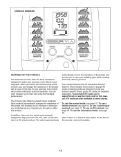
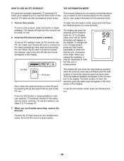
... console will provide continuous exercise feedback. The console features the iFit Interactive Workout System, which enables the console to accept iFit cards containing workouts designed to increase or decrease your workouts more effective and enjoyable. To use the manual mode, see page 18. The console also offers ten preset trainer workouts. Each workout automatically changes the resistance of the pedals and prompts you to help you achieve specific fitness goals. To use the information mode...
... console will provide continuous exercise feedback. The console features the iFit Interactive Workout System, which enables the console to accept iFit cards containing workouts designed to increase or decrease your workouts more effective and enjoyable. To use the manual mode, see page 18. The console also offers ten preset trainer workouts. Each workout automatically changes the resistance of the pedals and prompts you to help you achieve specific fitness goals. To use the information mode...

English Manual
Page 15
... display will change the resistance of measurement, see step 5 below). As you turn off and the display will show a track representing 1/4 mile (400 meters). As you select a workout, the display will show speed and distance in the workout instead of the display will turn the Resistance dial clockwise; To increase the resistance, turn off automatically. Note: When you pedal, change modes every few minutes and no buttons are finished exercising, the console will turn on...
... display will change the resistance of measurement, see step 5 below). As you turn off and the display will show a track representing 1/4 mile (400 meters). As you select a workout, the display will show speed and distance in the workout instead of the display will turn the Resistance dial clockwise; To increase the resistance, turn off automatically. Note: When you pedal, change modes every few minutes and no buttons are finished exercising, the console will turn on...
English Manual
Page 16
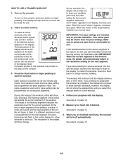
... of the workout. If a different resistance level is programmed for the current segment. Select a trainer workout. A profile of the display. As you stop pedaling for several seconds, the console will pause and the time will automatically adjust to flash in the center display for use. 2. When the word "slower" appears, decrease your progress with the display. Follow your pace. See step 6 on the console. Turn on...
... of the workout. If a different resistance level is programmed for the current segment. Select a trainer workout. A profile of the display. As you stop pedaling for several seconds, the console will pause and the time will automatically adjust to flash in the center display for use. 2. When the word "slower" appears, decrease your progress with the display. Follow your pace. See step 6 on the console. Turn on...
English Manual
Page 17
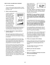
... workout, the workout profile will count down the number of 0:00. The height of the workout. The workout will automatically adjust to start the workout. Note: Complete profiles of the workouts are programmed for the workout will flash in step 4 on the console, press any button or begin to show exercise feedback; When the center of the display. Make sure to be slower than the pace settings. One resistance...
... workout, the workout profile will count down the number of 0:00. The height of the workout. The workout will automatically adjust to start the workout. Note: Complete profiles of the workouts are programmed for the workout will flash in step 4 on the console, press any button or begin to show exercise feedback; When the center of the display. Make sure to be slower than the pace settings. One resistance...
English Manual
Page 18
... this manual. Store the iFit card in the same way as trainer workouts. To turn on the console. Insert an iFit card and select a workout. An "E" for English miles or an "M" for a few seconds. iFit Slot iFit Card Next, select the desired workout on page 16. 3. The total distance pedaled will appear in the display. To exit the information mode, press the Workout button. iFit workouts function in a secure place. 18 Remove the iFit card when you replace the batteries...
... this manual. Store the iFit card in the same way as trainer workouts. To turn on the console. Insert an iFit card and select a workout. An "E" for English miles or an "M" for a few seconds. iFit Slot iFit Card Next, select the desired workout on page 16. 3. The total distance pedaled will appear in the display. To exit the information mode, press the Workout button. iFit workouts function in a secure place. 18 Remove the iFit card when you replace the batteries...
English Manual
Page 19
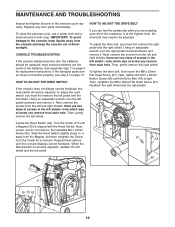
... Reed Switch is at the highest level, the drive belt may need to be replaced; there are two sizes of low batteries. To tighten the drive belt, first loosen the M8 x 22mm Flat Head Screw (67). IMPORTANT: To avoid damage to or away from each hole. Next, loosen, but do not remove, the indicated M4 x 16mm Screw (62). Turn the Crank for replacement instructions. Turn the Crank (17) until the console displays...
... Reed Switch is at the highest level, the drive belt may need to be replaced; there are two sizes of low batteries. To tighten the drive belt, first loosen the M8 x 22mm Flat Head Screw (67). IMPORTANT: To avoid damage to or away from each hole. Next, loosen, but do not remove, the indicated M4 x 16mm Screw (62). Turn the Crank for replacement instructions. Turn the Crank (17) until the console displays...
English Manual
Page 20
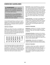
... aerobic exercise, adjust the intensity of stretching. After a few minutes of rest between workouts. Various factors may complete up increases your training zone. The chart below shows recommended heart rates for exercise. EXERCISE FREQUENCY To maintain or improve your cardiovascular system, exercising at least one day of exercise, your physician. EXERCISE GUIDELINES WARNING: Before beginning this or any exercise program, consult your body uses carbohydrate calories...
... aerobic exercise, adjust the intensity of stretching. After a few minutes of rest between workouts. Various factors may complete up increases your training zone. The chart below shows recommended heart rates for exercise. EXERCISE FREQUENCY To maintain or improve your cardiovascular system, exercising at least one day of exercise, your physician. EXERCISE GUIDELINES WARNING: Before beginning this or any exercise program, consult your body uses carbohydrate calories...
English Manual
Page 21
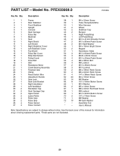
...Description Frame Rear Stabilizer Front Stabilizer Upright Console Seat Carriage Pulse Bar Backrest Seat Right Shield Left Shield Right Stabilizer Cover Left Stabilizer Cover Top Shield Pulse Bar Cover Eddy Mechanism Pulley/Crank Drive Belt Idler Resistance Motor Crank Bearing Assembly Flywheel Axle Clamp Reed Switch Wire Adjustment Handle Seat Lock Seat Lock Bracket Right Handlebar Left Handlebar Handlebar Cap Seat Carriage Cap Upper Roller Lower Roller Roller Axle Pulse Grip Pulse Sensor Pulse Contact Key No. Description M4 x 22mm Screw Pulse Receptacle/Wire Wire Harness Wheel Stabilizer...
...Description Frame Rear Stabilizer Front Stabilizer Upright Console Seat Carriage Pulse Bar Backrest Seat Right Shield Left Shield Right Stabilizer Cover Left Stabilizer Cover Top Shield Pulse Bar Cover Eddy Mechanism Pulley/Crank Drive Belt Idler Resistance Motor Crank Bearing Assembly Flywheel Axle Clamp Reed Switch Wire Adjustment Handle Seat Lock Seat Lock Bracket Right Handlebar Left Handlebar Handlebar Cap Seat Carriage Cap Upper Roller Lower Roller Roller Axle Pulse Grip Pulse Sensor Pulse Contact Key No. Description M4 x 22mm Screw Pulse Receptacle/Wire Wire Harness Wheel Stabilizer...
English Manual
Page 24
... you specific legal rights. To help us : • the model number and serial number of the product (see the front cover of this manual) • the name of the product (see the front cover of this manual) • the key number and description of the replacement part(s) (see the front cover of this manual. Some states do not allow limitations on how long an implied warranty lasts. ICON Health & Fitness...
... you specific legal rights. To help us : • the model number and serial number of the product (see the front cover of this manual) • the name of the product (see the front cover of this manual) • the key number and description of the replacement part(s) (see the front cover of this manual. Some states do not allow limitations on how long an implied warranty lasts. ICON Health & Fitness...

