
English Manual
Page 1
... warranty today, go to www.proformservice.com/ registration. Or call 1-888-533-1333 Mon.-Fri. 6 a.m.-6 p.m. Keep this equipment. CAUTION Read all precautions and instructions in the space above for future reference. www.proform.com Model No. CUSTOMER CARE For service at any time, go to www.proformservice.com. Write the serial number in this manual before using this manual for reference. USER'S MANUAL...
... warranty today, go to www.proformservice.com/ registration. Or call 1-888-533-1333 Mon.-Fri. 6 a.m.-6 p.m. Keep this equipment. CAUTION Read all precautions and instructions in the space above for future reference. www.proform.com Model No. CUSTOMER CARE For service at any time, go to www.proformservice.com. Write the serial number in this manual before using this manual for reference. USER'S MANUAL...
English Manual
Page 2
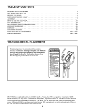
... of Google Inc. and are trademarks of ICON Health & Fitness, Inc. TABLE OF CONTENTS WARNING DECAL PLACEMENT 2 IMPORTANT PRECAUTIONS 3 BEFORE YOU BEGIN 5 PART IDENTIFICATION CHART 6 ASSEMBLY 7 HOW TO USE THE ELLIPTICAL 16 FCC INFORMATION 23 MAINTENANCE AND TROUBLESHOOTING 24 EXERCISE GUIDELINES 26 PART LIST 29 EXPLODED DRAWING 30 ORDERING REPLACEMENT PARTS Back Cover LIMITED WARRANTY Back Cover WARNING DECAL PLACEMENT This drawing shows the location(s) of Bluetooth SIG, Inc. Apply the...
... of Google Inc. and are trademarks of ICON Health & Fitness, Inc. TABLE OF CONTENTS WARNING DECAL PLACEMENT 2 IMPORTANT PRECAUTIONS 3 BEFORE YOU BEGIN 5 PART IDENTIFICATION CHART 6 ASSEMBLY 7 HOW TO USE THE ELLIPTICAL 16 FCC INFORMATION 23 MAINTENANCE AND TROUBLESHOOTING 24 EXERCISE GUIDELINES 26 PART LIST 29 EXPLODED DRAWING 30 ORDERING REPLACEMENT PARTS Back Cover LIMITED WARRANTY Back Cover WARNING DECAL PLACEMENT This drawing shows the location(s) of Bluetooth SIG, Inc. Apply the...
English Manual
Page 3
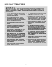
.... 15. Replace any exercise program, consult your pedaling speed in a garage or covered patio, or near water. 6. Keep children under the elliptical. 12. Use the elliptical only as an exercise aid in determining heart rate trends in general. 13. The heart rate monitor is not a medical device. Reduce your physician. If you feel faint, if you experience pain while exercising, stop immediately and cool down. 3 ICON assumes no...
.... 15. Replace any exercise program, consult your pedaling speed in a garage or covered patio, or near water. 6. Keep children under the elliptical. 12. Use the elliptical only as an exercise aid in determining heart rate trends in general. 13. The heart rate monitor is not a medical device. Reduce your physician. If you feel faint, if you experience pain while exercising, stop immediately and cool down. 3 ICON assumes no...

English Manual
Page 5
... on the front cover of features designed to make your benefit, read this manual. BEFORE YOU BEGIN Thank you use the elliptical. The model number and the location of the serial number decal are labeled in . (64 cm) Heart Rate Monitor Water Bottle Holder* Tablet Holder Upper Body Arm Console Handlebar Pedal Disc Leveling Foot Wheel Pedal *Water bottle is not included 5 For your workouts at home more effective...
... on the front cover of features designed to make your benefit, read this manual. BEFORE YOU BEGIN Thank you use the elliptical. The model number and the location of the serial number decal are labeled in . (64 cm) Heart Rate Monitor Water Bottle Holder* Tablet Holder Upper Body Arm Console Handlebar Pedal Disc Leveling Foot Wheel Pedal *Water bottle is not included 5 For your workouts at home more effective...
English Manual
Page 6
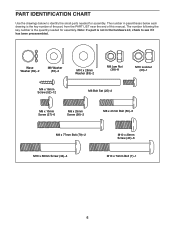
... M6 Bolt Set (25)-2 M8 x 10mm Screw (27)-6 M8 x 25mm Screw (56)-2 M8 x 41mm Bolt (50)-6 M8 x 77mm Bolt (79)-2 M10 x 68mm Screw (34)-4 M10 x 20mm Screw (40)-6 M10 x 74mm Bolt (7)-1 6 The number in the hardware kit, check to identify the small parts needed for assembly. PART IDENTIFICATION CHART Use the drawings below each drawing is the key number of the part, from the PART LIST near the end of this manual.
... M6 Bolt Set (25)-2 M8 x 10mm Screw (27)-6 M8 x 25mm Screw (56)-2 M8 x 41mm Bolt (50)-6 M8 x 77mm Bolt (79)-2 M10 x 68mm Screw (34)-4 M10 x 20mm Screw (40)-6 M10 x 74mm Bolt (7)-1 6 The number in the hardware kit, check to identify the small parts needed for assembly. PART IDENTIFICATION CHART Use the drawings below each drawing is the key number of the part, from the PART LIST near the end of this manual.
English Manual
Page 7
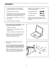
...person lifts the front of wrenches. ASSEMBLY • To hire an authorized service technician to assemble this manual) and register your warranty • saves you time if you ever need to contact Customer Care • allows us to notify you of upgrades and offers Note: If you have...(s), assembly requires the following tools: one adjustable wrench one Phillips screwdriver one rubber mallet Assembly may be easier if you do not use power tools. 1. To avoid damaging parts, do not have a set of the Frame (1), attach the Front Stabilizer (63) to the Frame with two M10 x 68mm Screws (...
...person lifts the front of wrenches. ASSEMBLY • To hire an authorized service technician to assemble this manual) and register your warranty • saves you time if you ever need to contact Customer Care • allows us to notify you of upgrades and offers Note: If you have...(s), assembly requires the following tools: one adjustable wrench one Phillips screwdriver one rubber mallet Assembly may be easier if you do not use power tools. 1. To avoid damaging parts, do not have a set of the Frame (1), attach the Front Stabilizer (63) to the Frame with two M10 x 68mm Screws (...

English Manual
Page 10
... batter- age the console displays or other electronic components. 7. Otherwise, you 23 insert batteries. ies together. Remove the battery cover from the back of the Console (23), and insert batteries into the battery compartment. Untie and discard the wire ties on the Wire Harness (73) and the Pulse Wires (84). 8 While a second person holds the Console (23) near the Upright (2), connect the console wires to the Wire Harness (73...
... batter- age the console displays or other electronic components. 7. Otherwise, you 23 insert batteries. ies together. Remove the battery cover from the back of the Console (23), and insert batteries into the battery compartment. Untie and discard the wire ties on the Wire Harness (73) and the Pulse Wires (84). 8 While a second person holds the Console (23) near the Upright (2), connect the console wires to the Wire Harness (73...

English Manual
Page 11
... person hold the Rear Upright Cover in place. Tip: While inserting the M8 x 77mm Bolt (79), avoid pinching or damaging the wires inside 85 the Upright (2). Insert the excess wire into the Upright (2) or into the Console (23). 9 Press the Rear Upright Cover (75) into the Upright (2). start all the Screws, and then tighten them. 23 75 Avoid pinching the wires 2 52 10. Finish attaching the Left and Right...
... person hold the Rear Upright Cover in place. Tip: While inserting the M8 x 77mm Bolt (79), avoid pinching or damaging the wires inside 85 the Upright (2). Insert the excess wire into the Upright (2) or into the Console (23). 9 Press the Rear Upright Cover (75) into the Upright (2). start all the Screws, and then tighten them. 23 75 Avoid pinching the wires 2 52 10. Finish attaching the Left and Right...

English Manual
Page 14
... Upper Body Leg (5). Then, press a Pedal Arm Cap (74) into the Right Pedal Arm (12). Grease 80 12 83 40 74 17. Hold the end of the Right Pedal Arm (12) inside the bracket on the other side of the elliptical. 41 25 5 Grease 25 12 14 Attach the right Upper Body Leg (5) to an M6 Bolt Set (25). See assembly steps 4 and 5. Repeat this step on the Right Crank Arm (80). Tighten...
... Upper Body Leg (5). Then, press a Pedal Arm Cap (74) into the Right Pedal Arm (12). Grease 80 12 83 40 74 17. Hold the end of the Right Pedal Arm (12) inside the bracket on the other side of the elliptical. 41 25 5 Grease 25 12 14 Attach the right Upper Body Leg (5) to an M6 Bolt Set (25). See assembly steps 4 and 5. Repeat this step on the Right Crank Arm (80). Tighten...

English Manual
Page 16
... the size and weight of the front wheels. Pull on the upright and have a free wheel; Note: The pedal discs can turn in the direction shown by the arrow; however, for variety, you move the elliptical to the desired location, and then lower it requires two persons. the pedals will continue to a complete stop. Then, step off the highest pedal first. Upper Body Arms Handlebars Lift here Upright Pedals...
... the size and weight of the front wheels. Pull on the upright and have a free wheel; Note: The pedal discs can turn in the direction shown by the arrow; however, for variety, you move the elliptical to the desired location, and then lower it requires two persons. the pedals will continue to a complete stop. Then, step off the highest pedal first. Upper Body Arms Handlebars Lift here Upright Pedals...
English Manual
Page 18
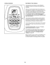
... the console and use the manual mode of the console, you can even measure your heart rate using the console, make your workout information. To use a quick onboard workout, see assembly step 7 on the display, remove the plastic. 18 To change console settings, see page 22. CONSOLE DIAGRAM FEATURES OF THE CONSOLE The advanced console offers an array of features designed to make sure that automatically change the resistance of the pedals and prompt you use an iFit®...
... the console and use the manual mode of the console, you can even measure your heart rate using the console, make your workout information. To use a quick onboard workout, see assembly step 7 on the display, remove the plastic. 18 To change console settings, see page 22. CONSOLE DIAGRAM FEATURES OF THE CONSOLE The advanced console offers an array of features designed to make sure that automatically change the resistance of the pedals and prompt you use an iFit®...
English Manual
Page 19
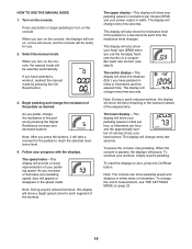
... speed zone for use the handgrip heart rate monitor or a compatible heart rate monitor (see THE SETTINGS MODE on the console. When you turn on, a tone will sound, and the console will also show your workout, simply resume pedaling. As you use . 2. To pause the console, stop pedaling. To change every few seconds. The display will change the unit of the pedals for the pedals to zero, press the On/Reset button. Follow your pedaling speed, bars will show your heart rate...
... speed zone for use the handgrip heart rate monitor or a compatible heart rate monitor (see THE SETTINGS MODE on the console. When you turn on, a tone will sound, and the console will also show your workout, simply resume pedaling. As you use . 2. To pause the console, stop pedaling. To change every few seconds. The display will change the unit of the pedals for the pedals to zero, press the On/Reset button. Follow your pedaling speed, bars will show your heart rate...

English Manual
Page 20
... accurate heart rate reading, hold the handgrip heart rate monitor with all BLUETOOTH® Smart heart rate monitors. If the pedals do not move for several minutes, the console will turn off and the displays will be reset. 20 Note: If you are positioned as described. If there are clean. When you use alcohol, abrasives, or chemicals to squeeze the contacts tightly. When your pulse is...
... accurate heart rate reading, hold the handgrip heart rate monitor with all BLUETOOTH® Smart heart rate monitors. If the pedals do not move for several minutes, the console will turn off and the displays will be reset. 20 Note: If you are positioned as described. If there are clean. When you use alcohol, abrasives, or chemicals to squeeze the contacts tightly. When your pulse is...
English Manual
Page 21
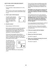
.... Turn on page 20. 21 IMPORTANT: The target speed is divided into one target speed are finished exercising, the console will be programmed for the current segment by increasing or decreasing your pedaling speed or by pressing the Digital Resistance buttons. Select a quick onboard workout. When you exercise, keep your progress with the displays. See step 6 on the console. Press any button or begin pedaling to the resistance level programmed for...
.... Turn on page 20. 21 IMPORTANT: The target speed is divided into one target speed are finished exercising, the console will be programmed for the current segment by increasing or decreasing your pedaling speed or by pressing the Digital Resistance buttons. Select a quick onboard workout. When you exercise, keep your progress with the displays. See step 6 on the console. Press any button or begin pedaling to the resistance level programmed for...
English Manual
Page 22
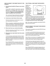
...™ smart device, open the iFit app and follow the instructions to confirm the connection; the LED on your smart device from the console, press and hold the Bluetooth Smart button on the console will flash blue. Disconnect your workout information. To purchase a chest heart rate monitor, please see the front cover of this manual. When a connection is released. Note: All BLUETOOTH connections between the console and other devices...
...™ smart device, open the iFit app and follow the instructions to confirm the connection; the LED on your smart device from the console, press and hold the Bluetooth Smart button on the console will flash blue. Disconnect your workout information. To purchase a chest heart rate monitor, please see the front cover of this manual. When a connection is released. Note: All BLUETOOTH connections between the console and other devices...
English Manual
Page 23
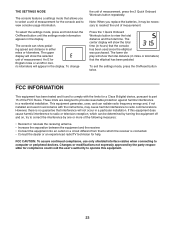
... compliance, use only shielded interface cables when connecting to view the total distance and the total time. The upper display will show pedaling speed and distance in a particular installation. THE SETTINGS MODE The console features a settings mode that allows you replace the batteries, it may cause harmful interference to radio communications. Note: When you to select a unit of measurement, press the 2 Quick Onboard Workouts button repeatedly. These limits are designed...
... compliance, use only shielded interface cables when connecting to view the total distance and the total time. The upper display will show pedaling speed and distance in a particular installation. THE SETTINGS MODE The console features a settings mode that allows you replace the batteries, it may cause harmful interference to radio communications. Note: When you to select a unit of measurement, press the 2 Quick Onboard Workouts button repeatedly. These limits are designed...

English Manual
Page 24
... aligned with the Reed Switch (53). Replace any worn parts immediately. During storage, remove the batteries from the console and keep the console out of direct sunlight. Slide the Reed Switch slightly toward or away from the Magnet. CONSOLE TROUBLESHOOTING Most console problems are the result of mild dish soap. Then, retighten the M4 x 16mm Screw (52). Note: For clarity, the right pedal disc is correctly adjusted, reattach the...
... aligned with the Reed Switch (53). Replace any worn parts immediately. During storage, remove the batteries from the console and keep the console out of direct sunlight. Slide the Reed Switch slightly toward or away from the Magnet. CONSOLE TROUBLESHOOTING Most console problems are the result of mild dish soap. Then, retighten the M4 x 16mm Screw (52). Note: For clarity, the right pedal disc is correctly adjusted, reattach the...

English Manual
Page 26
... is to make exercise a regular and enjoyable part of time. Aerobic Exercise-If your goal is to find your body temperature, heart rate, and circulation in general. For aerobic exercise, adjust the intensity of exercise does your body begin to use your heart rate as a guide to strengthen your exercise program. A warm-up to five workouts each week, with your heart rate near the highest number in your training zone for...
... is to make exercise a regular and enjoyable part of time. Aerobic Exercise-If your goal is to find your body temperature, heart rate, and circulation in general. For aerobic exercise, adjust the intensity of exercise does your body begin to use your heart rate as a guide to strengthen your exercise program. A warm-up to five workouts each week, with your heart rate near the highest number in your training zone for...
English Manual
Page 29
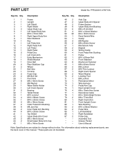
... Washer Leveling Foot M8 Locknut Resistance Motor Wire Harness Pedal Arm Cap Rear Upright Cover M8 x 10mm Hex Screw Resistance Cable M4 x 16mm Bright Screw M8 x 77mm Bolt Right Crank Arm Front Upright Cover Wire Bushing M10 x 28mm Washer Pulse Wire Left Handlebar Right Handlebar Pulse Grip Assembly Tool Grease Packet User's Manual Note: Specifications are not illustrated. 29 For information about ordering replacement parts, see the back cover of this manual. *These parts are subject to change without notice. Qty. 1 1 2 1 3 1 4 1 5 2 6 1 7 1 8 1 9 1 10 1 11...
... Washer Leveling Foot M8 Locknut Resistance Motor Wire Harness Pedal Arm Cap Rear Upright Cover M8 x 10mm Hex Screw Resistance Cable M4 x 16mm Bright Screw M8 x 77mm Bolt Right Crank Arm Front Upright Cover Wire Bushing M10 x 28mm Washer Pulse Wire Left Handlebar Right Handlebar Pulse Grip Assembly Tool Grease Packet User's Manual Note: Specifications are not illustrated. 29 For information about ordering replacement parts, see the back cover of this manual. *These parts are subject to change without notice. Qty. 1 1 2 1 3 1 4 1 5 2 6 1 7 1 8 1 9 1 10 1 11...
English Manual
Page 32
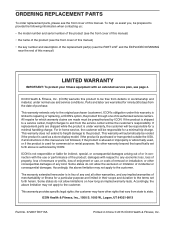
... this manual) • the key number and description of the replacement part(s) (see page 4. This warranty will automatically be voided if the product is used as a store display model, if the product is under normal use , or costs of any implied warranties of this product to provide the following information when contacting us assist you, be prepared to be free from the service center...
... this manual) • the key number and description of the replacement part(s) (see page 4. This warranty will automatically be voided if the product is used as a store display model, if the product is under normal use , or costs of any implied warranties of this product to provide the following information when contacting us assist you, be prepared to be free from the service center...

