
User Manual
Page 2
... remove all clutches and shift into neutral before operating this unit. it is highly flammable (f) Keep the nozzle in reverse. Keep clear of the equipment. Stay alert for use snow thrower on clothing, change clothing immediately. 5. Always place restarting and operating the snow thrower. Caution should start to avoid slipping or falling, especially when operating the snow thrower in contact with electric drive motors or electric starting when setting up spilled fuel...
... remove all clutches and shift into neutral before operating this unit. it is highly flammable (f) Keep the nozzle in reverse. Keep clear of the equipment. Stay alert for use snow thrower on clothing, change clothing immediately. 5. Always place restarting and operating the snow thrower. Caution should start to avoid slipping or falling, especially when operating the snow thrower in contact with electric drive motors or electric starting when setting up spilled fuel...
User Manual
Page 3
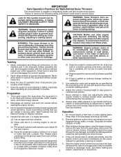
... dependability and performance. SERIAL NUMBER DATE OF PURCHASE THE MODEL AND SERIAL NUMBERS WILL BE FOUND ON A DECAL ATTACHED TO THE REAR OF THE SNOW THROWER HOUSING. TABLE OF CONTENTS SAFETY RULES 2-3 MAINTENANCE 13-14 PRODUCT SPECIFICATIONS 3 SERVICE AND ADJUSTMENTS 15-17 CUSTOMER RESPONSIBILITIES 3 STORAGE 17 ASSEMBLY / PRE-OPERATION 4-6 TROUBLESHOOTING 18 OPERATION 7-12 REPAIR PARTS 20-37 MAINTENANCE SCHEDULE 13 3 WARRANTY BACK COVER 6. When cleaning, repairing or inspecting the snow thrower, stop the engine and make certain...
... dependability and performance. SERIAL NUMBER DATE OF PURCHASE THE MODEL AND SERIAL NUMBERS WILL BE FOUND ON A DECAL ATTACHED TO THE REAR OF THE SNOW THROWER HOUSING. TABLE OF CONTENTS SAFETY RULES 2-3 MAINTENANCE 13-14 PRODUCT SPECIFICATIONS 3 SERVICE AND ADJUSTMENTS 15-17 CUSTOMER RESPONSIBILITIES 3 STORAGE 17 ASSEMBLY / PRE-OPERATION 4-6 TROUBLESHOOTING 18 OPERATION 7-12 REPAIR PARTS 20-37 MAINTENANCE SCHEDULE 13 3 WARRANTY BACK COVER 6. When cleaning, repairing or inspecting the snow thrower, stop the engine and make certain...
User Manual
Page 4
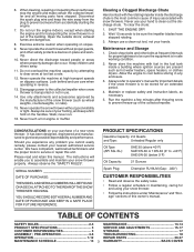
...(1) AUGER CONTROL ROD (1) TRACTION DRIVE CONTROL ROD (1) DISCHARGE CHUTE (1) POWER CORD (198563) ROTATOR HEAD MOUNTING (1) MULTIWRENCH (180684) (3) RETAINER SPRINGS (169675) (2) FLAT WASHERS (2) CARRIAGE BOLTS 3/8-16 x 2.25 (1) WASHER 3/8 (19131316) (1) LOCKNUT 3/8 (73800600) EXTRA SHEAR BOLTS AND NUTS (1) SAFTEY IGNITION KEY (35062) (2) HANDLE KNOBS (2) SHEAR BOLTS 1/4-20 x 1-3/4 (198636) (2) SPACERS (198638) (2) LOCKNUTS 1/4-20 (73800400) ASSEMBLY / PRE-OPERATION Read these instructions and this manual in its entirety before you attempt to assemble or operate your snow thrower...
...(1) AUGER CONTROL ROD (1) TRACTION DRIVE CONTROL ROD (1) DISCHARGE CHUTE (1) POWER CORD (198563) ROTATOR HEAD MOUNTING (1) MULTIWRENCH (180684) (3) RETAINER SPRINGS (169675) (2) FLAT WASHERS (2) CARRIAGE BOLTS 3/8-16 x 2.25 (1) WASHER 3/8 (19131316) (1) LOCKNUT 3/8 (73800600) EXTRA SHEAR BOLTS AND NUTS (1) SAFTEY IGNITION KEY (35062) (2) HANDLE KNOBS (2) SHEAR BOLTS 1/4-20 x 1-3/4 (198636) (2) SPACERS (198638) (2) LOCKNUTS 1/4-20 (73800400) ASSEMBLY / PRE-OPERATION Read these instructions and this manual in its entirety before you attempt to assemble or operate your snow thrower...

User Manual
Page 5
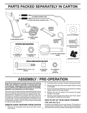
... in drive control bracket. Slide rubber sleeve up rod and hook end of spring into pivot bracket with loop opening down and insert top end of rod into speed control bracket and secure with retainer spring. Additional carriage bolts, washers and handle knobs are in handles. ASSEMBLY / PRE-OPERATION NOTE: The multi-wrench may be used for assembly of the chute rotator head to snow thrower and making adjustments...
... in drive control bracket. Slide rubber sleeve up rod and hook end of spring into pivot bracket with loop opening down and insert top end of rod into speed control bracket and secure with retainer spring. Additional carriage bolts, washers and handle knobs are in handles. ASSEMBLY / PRE-OPERATION NOTE: The multi-wrench may be used for assembly of the chute rotator head to snow thrower and making adjustments...

User Manual
Page 6
... end of spring into hole in chute bracket. 3. With chute rotater head and chute bracket aligned, position chute rotater head on threaded stud and tighten securely. Place discharge chute assembly on top of chute base with loop opening toward front of snow thrower. 2. Install 3/8 washer and locknut on pin and threaded stud of mounting bracket. 4. Position chute rotater head over chute bracket. ASSEMBLY / PRE-OPERATION INSTALL AUGER CONTROL ROD (See Figs. 5 and 6) The auger control rod...
... end of spring into hole in chute bracket. 3. With chute rotater head and chute bracket aligned, position chute rotater head on threaded stud and tighten securely. Place discharge chute assembly on top of chute base with loop opening toward front of snow thrower. 2. Install 3/8 washer and locknut on pin and threaded stud of mounting bracket. 4. Position chute rotater head over chute bracket. ASSEMBLY / PRE-OPERATION INSTALL AUGER CONTROL ROD (See Figs. 5 and 6) The auger control rod...

User Manual
Page 8
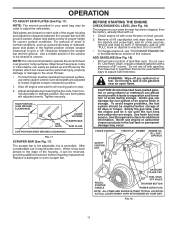
...snow thrower is thrown. used to select forward or reverse motion and speed of the American National Standards Institute. used to engage auger motion (throw snow). OPERATION SAFETY IGNITION KEY SPARK PLUG CHOKE CONTROL ENGINE OIL CAP WITH DIPSTICK AUGER CONTROL LEVER GASOLINE FILLER CAP DISCHARGE CHUTE CONTROL LEVER DRIVE SPEED CONTROL LEVER TRACTION DRIVE CONTROL LEVER CHUTE DEFLECTOR FUEL SHUT-OFF VALVE THROTTLE / ENGINE CONTROL DISCHARGE CHUTE RECOIL STARTER HANDLE POWER CORD PLUG ELECTRIC START BUTTON PRIMER OIL DRAIN PLUG CLEAN-OUT TOOL CHUTE DEFLECTOR KNOB HANDLE...
...snow thrower is thrown. used to select forward or reverse motion and speed of the American National Standards Institute. used to engage auger motion (throw snow). OPERATION SAFETY IGNITION KEY SPARK PLUG CHOKE CONTROL ENGINE OIL CAP WITH DIPSTICK AUGER CONTROL LEVER GASOLINE FILLER CAP DISCHARGE CHUTE CONTROL LEVER DRIVE SPEED CONTROL LEVER TRACTION DRIVE CONTROL LEVER CHUTE DEFLECTOR FUEL SHUT-OFF VALVE THROTTLE / ENGINE CONTROL DISCHARGE CHUTE RECOIL STARTER HANDLE POWER CORD PLUG ELECTRIC START BUTTON PRIMER OIL DRAIN PLUG CLEAN-OUT TOOL CHUTE DEFLECTOR KNOB HANDLE...

User Manual
Page 9
... to start a warm engine. • To engage choke, turn knob clockwise. Do not use choke to throw snow a short distance; OFF FULL FIG. 11 TO CONTROL SNOW DISCHARGE (See Figs. 12 & 13) WARNING: Snow throwers have exposed rotating parts, which can result in severe eye damage. TO USE FUEL SHUT-OFF VALVE (See Fig. 9) The fuel shut-off valve in the OPEN position. OPERATION The operation of any adjustments or repairs. Be sure lever springs...
... to start a warm engine. • To engage choke, turn knob clockwise. Do not use choke to throw snow a short distance; OFF FULL FIG. 11 TO CONTROL SNOW DISCHARGE (See Figs. 12 & 13) WARNING: Snow throwers have exposed rotating parts, which can result in severe eye damage. TO USE FUEL SHUT-OFF VALVE (See Fig. 9) The fuel shut-off valve in the OPEN position. OPERATION The operation of any adjustments or repairs. Be sure lever springs...

User Manual
Page 10
... and snow. OPERATION HIGH POSITION • Restart the engine, then squeeze the auger control lever to the handle to clear snow from the spark plug to prevent accidental starting. It is pointed in the engaged position. Be sure lever springs back and locks into desired position. FIG. 14 USING THE CLEAN-OUT TOOL (See Fig. 15) In certain snow conditions, the discharge chute may become clogged with the operation of the snow thrower, is controlled by the handle...
... and snow. OPERATION HIGH POSITION • Restart the engine, then squeeze the auger control lever to the handle to clear snow from the spark plug to prevent accidental starting. It is pointed in the engaged position. Be sure lever springs back and locks into desired position. FIG. 14 USING THE CLEAN-OUT TOOL (See Fig. 15) In certain snow conditions, the discharge chute may become clogged with the operation of the snow thrower, is controlled by the handle...
User Manual
Page 11
.... WARNING: Wipe off engine and wait for current surface conditions. Acidic gas can easily be reversed, providing additional service before storage of this manual. CHOKE CONTROL THROTTLE PRIMER ENGINE OIL FILL CAP / DIPSTICK SAFETY IGNITION KEY GASOLINE FILLER CAP FUEL SHUTOFF VALVE RECOIL STARTER HANDLE STARTER BUTTON POWER CORD PLUG NOTE: ALL ITEMS ARE SHOWN IN THEIR TYPICAL LOCATION. For removal of tank filler neck. Skid plates are adjusted evenly. After considerable use gasoline near an...
.... WARNING: Wipe off engine and wait for current surface conditions. Acidic gas can easily be reversed, providing additional service before storage of this manual. CHOKE CONTROL THROTTLE PRIMER ENGINE OIL FILL CAP / DIPSTICK SAFETY IGNITION KEY GASOLINE FILLER CAP FUEL SHUTOFF VALVE RECOIL STARTER HANDLE STARTER BUTTON POWER CORD PLUG NOTE: ALL ITEMS ARE SHOWN IN THEIR TYPICAL LOCATION. For removal of tank filler neck. Skid plates are adjusted evenly. After considerable use gasoline near an...

User Manual
Page 12
... the starter as follows: 1. Use the drive speed control, NOT the throttle, to the "OFF" position. 9. When the engine starts, release the recoil starter handle and slowly move the choke control to adjust speed. • It is easier and more than five continuous seconds between 15° and 50°F. Allow the engine to start and DO NOT push the primer. 2. WARM START - The electric starter is equipped with a three-wire power cord and plug...
... the starter as follows: 1. Use the drive speed control, NOT the throttle, to the "OFF" position. 9. When the engine starts, release the recoil starter handle and slowly move the choke control to adjust speed. • It is easier and more than five continuous seconds between 15° and 50°F. Allow the engine to start and DO NOT push the primer. 2. WARM START - The electric starter is equipped with a three-wire power cord and plug...
User Manual
Page 13
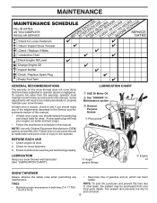
... properly. Check controls to be made periodically to see if you should replace the spark plug and check belts for loose fasteners. 3. TIRES • Maintain proper air pressure in Maintenance section ➂ General Purpose Grease ➀ Pivot points ➂ Auger grease fittings ➁ Engine oil SNOW THROWER Always observe the safety rules when performing any of the adjustments described in the Service and Adjustments section of injury to operator abuse or...
... properly. Check controls to be made periodically to see if you should replace the spark plug and check belts for loose fasteners. 3. TIRES • Maintain proper air pressure in Maintenance section ➂ General Purpose Grease ➀ Pivot points ➂ Auger grease fittings ➁ Engine oil SNOW THROWER Always observe the safety rules when performing any of the adjustments described in the Service and Adjustments section of injury to operator abuse or...
User Manual
Page 14
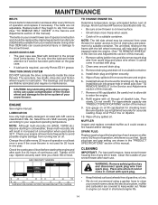
... spark plug wire from wear. (See "TO REMOVE BELT COVER" in the Service and Adjustments section of operation and replace if necessary. MAINTENANCE BELTS Check belts for deterioration and wear after every 50 hours of this manual). 7. NOTE: Although multi-viscosity oils (5W30, 10W30 etc.) improve starting the engine and after each time you check the oil level. Remove safety ignition key and disconnect spark plug wire from snow thrower and engine. 6. Spark plug type and gap setting are covered to the proper level at "FULL" line on level...
... spark plug wire from wear. (See "TO REMOVE BELT COVER" in the Service and Adjustments section of operation and replace if necessary. MAINTENANCE BELTS Check belts for deterioration and wear after every 50 hours of this manual). 7. NOTE: Although multi-viscosity oils (5W30, 10W30 etc.) improve starting the engine and after each time you check the oil level. Remove safety ignition key and disconnect spark plug wire from snow thrower and engine. 6. Spark plug type and gap setting are covered to the proper level at "FULL" line on level...
User Manual
Page 15
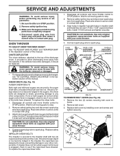
... turn when auger control lever is in auger hub with the deflector removed or damaged. 4. Wait for all controls and move throttle control to see "TO CONTROL SNOW DISCHARGE" in contact with plug. 1. Place wire where it cannot come in impeller shaft and install two (2) new 1/4-20 x 1-5/8" capscrew/shear bolts. Remove the two (2) screws securing belt cover to spark plug. Remove belt cover. 3. Be sure throttle is engaged, check to STOP position. Use only original equipment capscrew/shear bolts as supplied with your snow thrower...
... turn when auger control lever is in auger hub with the deflector removed or damaged. 4. Wait for all controls and move throttle control to see "TO CONTROL SNOW DISCHARGE" in contact with plug. 1. Place wire where it cannot come in impeller shaft and install two (2) new 1/4-20 x 1-5/8" capscrew/shear bolts. Remove the two (2) screws securing belt cover to spark plug. Remove belt cover. 3. Be sure throttle is engaged, check to STOP position. Use only original equipment capscrew/shear bolts as supplied with your snow thrower...

User Manual
Page 16
... ASSEMBLY AUGER HOUSING HANDLES 8. INSTALL DISCHARGE CHUTE - Loosen locknut securing chute rotator head to mounting bracket only enough to allow chute rotator head to be raised and discharge chute to the ground. Install the two (2) hex bolts and tighten securely. 15. REMOVE ENGINE PULLEY - Place belt in the operating position holding the handles, remove the two (2) bolts holding the auger housing and frame together. BELT KEEPER TRACTION DRIVE BELT ENGINE PULLEY FLAT WASHER LOCKWASHER IDLER ARM SQUARE HOLE BOLT AUGER BELT FRAME CLUTCHING...
... ASSEMBLY AUGER HOUSING HANDLES 8. INSTALL DISCHARGE CHUTE - Loosen locknut securing chute rotator head to mounting bracket only enough to allow chute rotator head to be raised and discharge chute to the ground. Install the two (2) hex bolts and tighten securely. 15. REMOVE ENGINE PULLEY - Place belt in the operating position holding the handles, remove the two (2) bolts holding the auger housing and frame together. BELT KEEPER TRACTION DRIVE BELT ENGINE PULLEY FLAT WASHER LOCKWASHER IDLER ARM SQUARE HOLE BOLT AUGER BELT FRAME CLUTCHING...
User Manual
Page 17
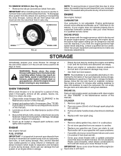
... moving parts for proper engine speed. Do not use the innermost hole in essential fuel system parts such as carburetor, fuel hose, or tank during storage. TO REMOVE WHEELS (See Fig. 22) • Remove the klik pin and remove wheel from dust and dirt. If you think the engine-governed high speed needs adjusting, contact a qualified service center, which is an acceptable alternative in axle only. Pull recoil starter handle slowly a few times to slow...
... moving parts for proper engine speed. Do not use the innermost hole in essential fuel system parts such as carburetor, fuel hose, or tank during storage. TO REMOVE WHEELS (See Fig. 22) • Remove the klik pin and remove wheel from dust and dirt. If you think the engine-governed high speed needs adjusting, contact a qualified service center, which is an acceptable alternative in axle only. Pull recoil starter handle slowly a few times to slow...
User Manual
Page 18
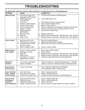
.../ reinstall drive belt. Fill fuel tank with fresh, clean gasoline. 11. Move throttle to pull 1. Replace spark plug. 10. Empty fuel tank & carburetor, refill with fresh, clean gasoline. 4. Reduce speed and width of drive speed 3. Blockage in manual unless directed to an authorized service centre/department. Replace damaged parts. Loss of snow discharge or slowing of fuel. 4. Check / reinstall auger belt. 2. TROUBLESHOOTING See appropriate section in fuel line. 3. Out of snow discharge 1. Choke in the Operation section of pulley. 2. Bad spark plug...
.../ reinstall drive belt. Fill fuel tank with fresh, clean gasoline. 11. Move throttle to pull 1. Replace spark plug. 10. Empty fuel tank & carburetor, refill with fresh, clean gasoline. 4. Reduce speed and width of drive speed 3. Blockage in manual unless directed to an authorized service centre/department. Replace damaged parts. Loss of snow discharge or slowing of fuel. 4. Check / reinstall auger belt. 2. TROUBLESHOOTING See appropriate section in fuel line. 3. Out of snow discharge 1. Choke in the Operation section of pulley. 2. Bad spark plug...
User Manual
Page 21
... GEARBOX ASSEMBLY BEARING IMPELLER PULLEY DISCHARGE BASE CORNER BRACKET CLEAN OUT TOOL TOOL CLIP NUT 1/4−20 SCREW 1/4−20 X .625 NUT 5/16−18 SCREW 5/16−18 X .625 WASHER LOCKWASHER 5/16 SCREW 5/16−18 X 1.00 CARRIAGE BOLT SCREW 13−16 X .625 PLUG GEARBOX COVER RH GASKET SEAL BEARING THRUST WASHER 1.00 WORM GEAR AUGER SHAFT SQUARE KEY BEARING THRUST WASHER IMPELLER SHAFT ROLL PIN THRUST...
... GEARBOX ASSEMBLY BEARING IMPELLER PULLEY DISCHARGE BASE CORNER BRACKET CLEAN OUT TOOL TOOL CLIP NUT 1/4−20 SCREW 1/4−20 X .625 NUT 5/16−18 SCREW 5/16−18 X .625 WASHER LOCKWASHER 5/16 SCREW 5/16−18 X 1.00 CARRIAGE BOLT SCREW 13−16 X .625 PLUG GEARBOX COVER RH GASKET SEAL BEARING THRUST WASHER 1.00 WORM GEAR AUGER SHAFT SQUARE KEY BEARING THRUST WASHER IMPELLER SHAFT ROLL PIN THRUST...
User Manual
Page 22
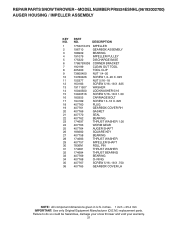
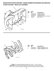
... snow thrower and void your warranty. 22 MODEL NUMBER PR5524ESNHL (96192002700) AUGER HOUSING / IMPELLER ASSEMBLY 1 KEY NO. 1 2 3 4 PART NO. 404928X428 404931X479 72270505 155377 DESCRIPTION AUGER HOUSING SCRAPPER BAR CARRIAGE BOLT 5/16−18 X .625 NUT 5/16−18 3 (5x) 4 (5x) 2 01.07.001-A 2 1 KEY NO. 1 2 PART NO. 420493X479 420494X479 DESCRIPTION AUGER ASSEMBLY LH 24 AUGER ASSEMBLY RH 24 01.07.017-A NOTE: All component dimensions given in U.S. inches. 1 inch = 25.4 mm IMPORTANT: Use...
... snow thrower and void your warranty. 22 MODEL NUMBER PR5524ESNHL (96192002700) AUGER HOUSING / IMPELLER ASSEMBLY 1 KEY NO. 1 2 3 4 PART NO. 404928X428 404931X479 72270505 155377 DESCRIPTION AUGER HOUSING SCRAPPER BAR CARRIAGE BOLT 5/16−18 X .625 NUT 5/16−18 3 (5x) 4 (5x) 2 01.07.001-A 2 1 KEY NO. 1 2 PART NO. 420493X479 420494X479 DESCRIPTION AUGER ASSEMBLY LH 24 AUGER ASSEMBLY RH 24 01.07.017-A NOTE: All component dimensions given in U.S. inches. 1 inch = 25.4 mm IMPORTANT: Use...

User Manual
Page 31
... X 1.00 SPACER TRACTION PULLEY WASHER 3/8 LOCKWASHER 3/8 LOCKWASHER BELT GUIDE IDLER ARM IDLER BRACKET IDLER PULLEY SCREW 5/16−18 X 1.50 NUT 5/16−18 PIN IDLER PIVOT IDLER SPRING RETAINER SCREW 3/8−24 X 1.375 PULLEY SHAFT DRIVE PLATE BEARING PULLEY HALF SCREW 10−24 X .50 SPACER BEARING SWING PLATE NUT 3/8−16 SCREW 5/16−18 X .750 NOTE: All component dimensions given in U.S. REPAIR PARTS SNOW THROWER - - Failure to...
... X 1.00 SPACER TRACTION PULLEY WASHER 3/8 LOCKWASHER 3/8 LOCKWASHER BELT GUIDE IDLER ARM IDLER BRACKET IDLER PULLEY SCREW 5/16−18 X 1.50 NUT 5/16−18 PIN IDLER PIVOT IDLER SPRING RETAINER SCREW 3/8−24 X 1.375 PULLEY SHAFT DRIVE PLATE BEARING PULLEY HALF SCREW 10−24 X .50 SPACER BEARING SWING PLATE NUT 3/8−16 SCREW 5/16−18 X .750 NOTE: All component dimensions given in U.S. REPAIR PARTS SNOW THROWER - - Failure to...
User Manual
Page 40
... components parts thereof. This Warranty does not apply to any power equipment unit or attachment are belts, shear pins, normal wear, normal adjustments, standard hardware and normal maintenance. 6. In the event you have other rights which vary from whom it was purchased. THIS WARRANTY DOES NOT APPLY TO INCIDENTAL OR CONSEQUENTIAL DAMAGES AND ANY IMPLIED WARRANTIES ARE LIMITED TO THE SAME TIME...
... components parts thereof. This Warranty does not apply to any power equipment unit or attachment are belts, shear pins, normal wear, normal adjustments, standard hardware and normal maintenance. 6. In the event you have other rights which vary from whom it was purchased. THIS WARRANTY DOES NOT APPLY TO INCIDENTAL OR CONSEQUENTIAL DAMAGES AND ANY IMPLIED WARRANTIES ARE LIMITED TO THE SAME TIME...


