

User Manual
Page 2
...before and while backing. • Beawareofthemowerdischargedirectionanddonotpoint it . Use only an approved container. - Check their ability to operate the riding mower safely enough to the machine and the mowing activity. Frequently check components and replace with the instructions, to operate the machine. ...offs, ditches, or embankments. Do not allow responsible adults, who are familiar with manufacturer's recommended parts, when necessary. • Mower blades are subject to wear, damage, and deterioration, which could be thrown. Choose a low gear so that children will not ...
...before and while backing. • Beawareofthemowerdischargedirectionanddonotpoint it . Use only an approved container. - Check their ability to operate the riding mower safely enough to the machine and the mowing activity. Frequently check components and replace with the instructions, to operate the machine. ...offs, ditches, or embankments. Do not allow responsible adults, who are familiar with manufacturer's recommended parts, when necessary. • Mower blades are subject to wear, damage, and deterioration, which could be thrown. Choose a low gear so that children will not ...

User Manual
Page 3
... its constituents, and certain vehicle components contain or emit chemicals known to the State of your tractor. SAFETY RULES Safe Operation Practices for Ride-On Mowers • Be sure the area is dangerous. If tires lose traction, disengage the blades and proceed slowly straight down the slope. • If machine stops...
... its constituents, and certain vehicle components contain or emit chemicals known to the State of your tractor. SAFETY RULES Safe Operation Practices for Ride-On Mowers • Be sure the area is dangerous. If tires lose traction, disengage the blades and proceed slowly straight down the slope. • If machine stops...
User Manual
Page 8
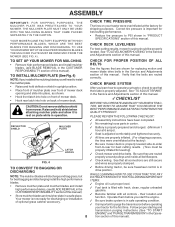
...plate in the CUSTOMER RESPONSABILITY section of this manual. FIG. 4 ✓ Check wiring. CHECK DECK LEVELNESS For best cutting results, mower housing should be properly inflated for best cutting performance. • Reduce tire pressure to rest on your tractor, check to -rear ...blades, (see that the belts are properly clamped. ASSEMBLY IMPORTANT: FOR SHIPPING PURPOSES, THE MULCHER PLATE WAS PREATTACHED TO YOUR MOWER. YOUR MOWER CAME FACTORY EQUIPPED WITH HIGH PERFORMANCE BLADES, WHICH ARE THE BEST BLADES FOR BAGGING AND DISCHARGING. Correct tire pressure is filled...
...plate in the CUSTOMER RESPONSABILITY section of this manual. FIG. 4 ✓ Check wiring. CHECK DECK LEVELNESS For best cutting results, mower housing should be properly inflated for best cutting performance. • Reduce tire pressure to rest on your tractor, check to -rear ...blades, (see that the belts are properly clamped. ASSEMBLY IMPORTANT: FOR SHIPPING PURPOSES, THE MULCHER PLATE WAS PREATTACHED TO YOUR MOWER. YOUR MOWER CAME FACTORY EQUIPPED WITH HIGH PERFORMANCE BLADES, WHICH ARE THE BEST BLADES FOR BAGGING AND DISCHARGING. Correct tire pressure is filled...

User Manual
Page 9
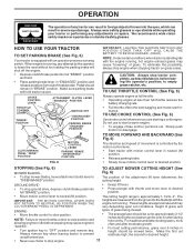
OPERATION These symbols may appear on your tractor or in literature supplied with the product. Learn and understand their meaning. BATTERY CAUTION OR WARNING REVERSE FORWARD FAST SLOW ENGINE ON ENGINE OFF OIL PRESSURE LIGHTS ON OVER TEMP LIGHT FUEL CHOKE MOWER HEIGHT PARKING BRAKE LOCKED UNLOCKED MOWER LIFT ATTACHMENT REVERSE CLUTCH ENGAGED NEUTRAL HIGH P LOW PARKING BRAKE 15 15 15 IGNITION ATTACHMENT CLUTCH DISENGAGED KEEP AREA CLEAR SLOPE HAZARDS (SEE SAFETY RULES SECTION) DANGER, KEEP HANDS AND FEET AWAY 9 FREE WHEEL (Automatic Models only)
OPERATION These symbols may appear on your tractor or in literature supplied with the product. Learn and understand their meaning. BATTERY CAUTION OR WARNING REVERSE FORWARD FAST SLOW ENGINE ON ENGINE OFF OIL PRESSURE LIGHTS ON OVER TEMP LIGHT FUEL CHOKE MOWER HEIGHT PARKING BRAKE LOCKED UNLOCKED MOWER LIFT ATTACHMENT REVERSE CLUTCH ENGAGED NEUTRAL HIGH P LOW PARKING BRAKE 15 15 15 IGNITION ATTACHMENT CLUTCH DISENGAGED KEEP AREA CLEAR SLOPE HAZARDS (SEE SAFETY RULES SECTION) DANGER, KEEP HANDS AND FEET AWAY 9 FREE WHEEL (Automatic Models only)

User Manual
Page 10
.... CLUTCH/BRAKE PEDAL: Used for declutching and braking the tractor and starting a cold engine. ATTACHMENT CLUTCH LEVER: Used to engage the mower blades, or other attachments mounted to familiarize yourself with the engine off . AMMETER - FREEWHEEL CONTROL: Disengages transmission for future reference. Indicates... PARKING BRAKE: Locks clutch/brake pedal into the brake position. ATTACHMENT LIFT LEVER: Used to raise, lower, and adjust the mower deck or other attachments mounted to your tractor to your tractor. THROTTLE CONTROL: Used for starting and stopping the engine. 10 ...
.... CLUTCH/BRAKE PEDAL: Used for declutching and braking the tractor and starting a cold engine. ATTACHMENT CLUTCH LEVER: Used to engage the mower blades, or other attachments mounted to familiarize yourself with the engine off . AMMETER - FREEWHEEL CONTROL: Disengages transmission for future reference. Indicates... PARKING BRAKE: Locks clutch/brake pedal into the brake position. ATTACHMENT LIFT LEVER: Used to raise, lower, and adjust the mower deck or other attachments mounted to your tractor to your tractor. THROTTLE CONTROL: Used for starting and stopping the engine. 10 ...
User Manual
Page 11
...your tractor or performing any adjustments or repairs. Pedal should be mowed twice. mance. STOPPING (See Fig. 6) TO ADJUST MOWER CUTTING HEIGHT (See MOWER BLADES - OPERATION The operation of any tractor can result in severe eye damage. When engine is approximately 1-1/2 to "OFF...first cut to approximately 2-1/2 inches during the cool season and to idle before leaving the operator's position; CAUTION: Always stop mower blades,move throttle control to slow position and allowing engine to over spectacles or standard safety glasses. The IMPORTANT: THE MOTION CONTROL...
...your tractor or performing any adjustments or repairs. Pedal should be mowed twice. mance. STOPPING (See Fig. 6) TO ADJUST MOWER CUTTING HEIGHT (See MOWER BLADES - OPERATION The operation of any tractor can result in severe eye damage. When engine is approximately 1-1/2 to "OFF...first cut to approximately 2-1/2 inches during the cool season and to idle before leaving the operator's position; CAUTION: Always stop mower blades,move throttle control to slow position and allowing engine to over spectacles or standard safety glasses. The IMPORTANT: THE MOTION CONTROL...
User Manual
Page 12
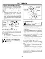
...shut off the engine. • Select desired height of cut position, gauge wheels should be assembled so they are slightly off the ground when mower is at more than 15° and do not drive across any slope. • Choose the slowest speed before starting up or down ...opposite side installing gauge wheel in same adjustment hole. 3/8-16 LOCKNUT GUAGE WHEEL MOUNTING BRACKET 3/8 WASHER GAUGE WHEEL SHOULDER BOLT FIG. 7 TO OPERATE MOWER (See Fig. 8) Your tractor is closed and secured to help prevent scalping in proper position to tractor. Gauge wheels then keep the deck in ...
...shut off the engine. • Select desired height of cut position, gauge wheels should be assembled so they are slightly off the ground when mower is at more than 15° and do not drive across any slope. • Choose the slowest speed before starting up or down ...opposite side installing gauge wheel in same adjustment hole. 3/8-16 LOCKNUT GUAGE WHEEL MOUNTING BRACKET 3/8 WASHER GAUGE WHEEL SHOULDER BOLT FIG. 7 TO OPERATE MOWER (See Fig. 8) Your tractor is closed and secured to help prevent scalping in proper position to tractor. Gauge wheels then keep the deck in ...
User Manual
Page 14
... by selecting a low enough gear to give best performance of this manual. After one minute for five (5) seconds. See "TO LEVEL MOWER HOUSING" in the Service and Adjustments section of the attachment being removed from shrubs, fences, driveways, etc. PURGE TRANSMISSION CAUTION: Never engage... to slow position. After the engine is running , move throttle control to half (1/2) speed. Repeat this procedure there will plug mower and leave undesirable clumps. FIG. 10 14 IMPORTANT: SHOULD YOUR TRANSMISSION REQUIRE REMOVAL FOR SERVICE OR REPLACEMENT, IT SHOULD BE PURGED ...
... by selecting a low enough gear to give best performance of this manual. After one minute for five (5) seconds. See "TO LEVEL MOWER HOUSING" in the Service and Adjustments section of the attachment being removed from shrubs, fences, driveways, etc. PURGE TRANSMISSION CAUTION: Never engage... to slow position. After the engine is running , move throttle control to half (1/2) speed. Repeat this procedure there will plug mower and leave undesirable clumps. FIG. 10 14 IMPORTANT: SHOULD YOUR TRANSMISSION REQUIRE REMOVAL FOR SERVICE OR REPLACEMENT, IT SHOULD BE PURGED ...

User Manual
Page 15
... mulch with the mulching action. Mow north to south one week then change to east to the direct sun. • For best results, adjust the mower cutting height so that an area be mulched a second time to completely hide the clippings. MAX 1/3 FIG. 11 15 Also, the mulched grass will disperse... grass has dried and the newly cut on each pass and mow slowly. • Certain types of grass and grass conditions may require that the mower cuts off only the top one-third of the lawn. For extremely heavy mulching, reduce your lawn is wet. OPERATION MULCHING MOWING TIPS IMPORTANT: FOR...
... mulch with the mulching action. Mow north to south one week then change to east to the direct sun. • For best results, adjust the mower cutting height so that an area be mulched a second time to completely hide the clippings. MAX 1/3 FIG. 11 15 Also, the mulched grass will disperse... grass has dried and the newly cut on each pass and mow slowly. • Certain types of grass and grass conditions may require that the mower cuts off only the top one-third of the lawn. For extremely heavy mulching, reduce your lawn is wet. OPERATION MULCHING MOWING TIPS IMPORTANT: FOR...
User Manual
Page 16
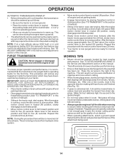
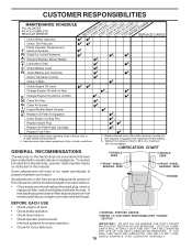
.... • Check brake operation. • Check tire pressure. • Check operator presence and interlock systems for proper operation. • Check for Loose Fasteners A Sharpen/Replace Mower Blades C T Lubrication Chart 0 Check Battery Level R Clean Battery and Terminals Check Transaxle Cooling Check V-Belts BEFOREEEVAECRHYU8ESVHEEORUYRS2E5VHEROYUR5E0SVEHROYUR1E0SV0EHROYUBSREESFAOSROENSSTEORRAVGEICE DATES 5 3 4 Check Engine Oil Level Change Engine Oil (with...
.... • Check brake operation. • Check tire pressure. • Check operator presence and interlock systems for proper operation. • Check for Loose Fasteners A Sharpen/Replace Mower Blades C T Lubrication Chart 0 Check Battery Level R Clean Battery and Terminals Check Transaxle Cooling Check V-Belts BEFOREEEVAECRHYU8ESVHEEORUYRS2E5VHEROYUR5E0SVEHROYUR1E0SV0EHROYUBSREESFAOSROENSSTEORRAVGEICE DATES 5 3 4 Check Engine Oil Level Change Engine Oil (with...
User Manual
Page 17
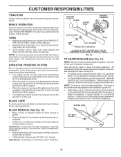
... systems are not. • Slide blade on a grinding wheel. Replace bent or damaged blades. BLADE REMOVAL (See Fig. 12) • Raise mower to highest position to allow access to blades. • Remove blade bolt, lock washer and flat washer securing blade. • Install new or resharpened... shut off the engine. • The attachment clutch should remain in a horizontal position. If your local parts dealer. BLADE CARE For best results mower blades must be adjusted. (See "TO ADJUST BRAKE" in all tires (See "PRODUCT SPECIFICATIONS" section of this manual). IMPORTANT: TO ENSURE PROPER ...
... systems are not. • Slide blade on a grinding wheel. Replace bent or damaged blades. BLADE REMOVAL (See Fig. 12) • Raise mower to highest position to allow access to blades. • Remove blade bolt, lock washer and flat washer securing blade. • Install new or resharpened... shut off the engine. • The attachment clutch should remain in a horizontal position. If your local parts dealer. BLADE CARE For best results mower blades must be adjusted. (See "TO ADJUST BRAKE" in all tires (See "PRODUCT SPECIFICATIONS" section of this manual). IMPORTANT: TO ENSURE PROPER ...

User Manual
Page 20
...TO BE MOUNTED ON THE TRACTOR, REMOVE THE FRONT LINKS AND HOOK THE CLUTCH SPRING INTO SQUARE HOLE IN FRAME. TRACTOR TO REMOVE MOWER (See Fig. 18) Mower will be easier to remove from the right side of bracket. • Disconnect anti-swaybar from chassis bracket by removing retainer springs.... • Raise lift lever to raise suspension arms. Slide mower out from under tractor with deflector shield to right side of tractor. • Lower lift lever to its lowest position. • Roll belt off...
...TO BE MOUNTED ON THE TRACTOR, REMOVE THE FRONT LINKS AND HOOK THE CLUTCH SPRING INTO SQUARE HOLE IN FRAME. TRACTOR TO REMOVE MOWER (See Fig. 18) Mower will be easier to remove from the right side of bracket. • Disconnect anti-swaybar from chassis bracket by removing retainer springs.... • Raise lift lever to raise suspension arms. Slide mower out from under tractor with deflector shield to right side of tractor. • Lower lift lever to its lowest position. • Roll belt off...

User Manual
Page 21
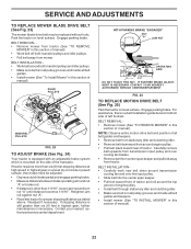
..."D" is in front and behind the mandrel at front than rear, tighten nut "F" against trunnion on both front links. • To raise front of mower, loosen nut "F" from bottom edge of this manual). MANDREL "D" "D" FIG. 21 BOTH FRONT LINKS MUST BE EQUAL IN LENGTH SUSPENSION ARM LIFT LINK .... 20 FRONT-TO-BACK ADJUSTMENT (See Figs. 21 and 22) IMPORTANT: DECK MUST BE LEVEL SIDE-TO-SIDE. SERVICE AND ADJUSTMENTS TO LEVEL MOWER HOUSING Adjust the mower while tractor is 1/8" to 1/2" lower at front than rear, tighten nuts "F" against trunnion on that side. • To lower one link...
..."D" is in front and behind the mandrel at front than rear, tighten nut "F" against trunnion on both front links. • To raise front of mower, loosen nut "F" from bottom edge of this manual). MANDREL "D" "D" FIG. 21 BOTH FRONT LINKS MUST BE EQUAL IN LENGTH SUSPENSION ARM LIFT LINK .... 20 FRONT-TO-BACK ADJUSTMENT (See Figs. 21 and 22) IMPORTANT: DECK MUST BE LEVEL SIDE-TO-SIDE. SERVICE AND ADJUSTMENTS TO LEVEL MOWER HOUSING Adjust the mower while tractor is 1/8" to 1/2" lower at front than rear, tighten nuts "F" against trunnion on that side. • To lower one link...
User Manual
Page 22
...pulley grooves and inside all belt guides and keepers. • Remove belt from stationary idler and clutching idler. • Remove belt downward from mower. WITH PARKING BRAKE "ENGAGED" 1-9/16" NUT "A" JAM NUT OPERATING ARM DO NOT TOUCH THIS NUT. For assistance, there is a belt ...22 Readjust if necessary. NOTE: Observe entire motion drive belt and position of all belt guides and keepers. • Install mower (See "TO INSTALL MOWER" in this section of manual). IF FURTHER BRAKE ADJUSTMENT IS NECESSARY CONTACT YOUR NEAREST AUTHORIZED SERVICE CENTER/DEPARTMENT FIG. 24 TO ...
...pulley grooves and inside all belt guides and keepers. • Remove belt from stationary idler and clutching idler. • Remove belt downward from mower. WITH PARKING BRAKE "ENGAGED" 1-9/16" NUT "A" JAM NUT OPERATING ARM DO NOT TOUCH THIS NUT. For assistance, there is a belt ...22 Readjust if necessary. NOTE: Observe entire motion drive belt and position of all belt guides and keepers. • Install mower (See "TO INSTALL MOWER" in this section of manual). IF FURTHER BRAKE ADJUSTMENT IS NECESSARY CONTACT YOUR NEAREST AUTHORIZED SERVICE CENTER/DEPARTMENT FIG. 24 TO ...

User Manual
Page 23
.... Insert square key. • Replace washers and snap retaining ring securely in rear wheel hub and axle. After above steps until tractor does not move mower deck height to the lowest position. Do not lose). • Repair tire and reassemble. • On rear wheels only: align grooves in axle groove. •...
.... Insert square key. • Replace washers and snap retaining ring securely in rear wheel hub and axle. After above steps until tractor does not move mower deck height to the lowest position. Do not lose). • Repair tire and reassemble. • On rear wheels only: align grooves in axle groove. •...
User Manual
Page 26
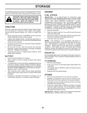
...with gasoline in contact with a suitable protective cover that all nuts, bolts and screws are empty. • Never use plastic. When mower is an acceptable alternative in the Customer Responsibilities section of this manual). • Lubricate as shown in the fuel tank or permanent damage...8226; Remove spark plug(s). • Pour one season to another. • Replace your gasoline can if your tractor to rust. TRACTOR Remove mower from one ounce of time in storage, battery may require recharging. • To help prevent corrosion and power leakage during storage. ENGINE FUEL ...
...with gasoline in contact with a suitable protective cover that all nuts, bolts and screws are empty. • Never use plastic. When mower is an acceptable alternative in the Customer Responsibilities section of this manual). • Lubricate as shown in the fuel tank or permanent damage...8226; Remove spark plug(s). • Pour one season to another. • Replace your gasoline can if your tractor to rust. TRACTOR Remove mower from one ounce of time in storage, battery may require recharging. • To help prevent corrosion and power leakage during storage. ENGINE FUEL ...

User Manual
Page 27
...replace fuel filter. 8. Clean/replace muffler. 13. Bent blade mandrel. 3. Carburetor out of grass, leaves and trash under mower. 4. Recharge or replace battery. 4. Attachment clutch is engaged. 3. Check all wiring. 14. Check/replace ignition switch. ...Dirty/clogged muffler. 13. Tighten loose part(s). Faulty ignition switch. 8. Clean battery terminals. 6. Faulty solenoid or starter. 9. Loss of mower housing. 4. Excessive vibration 1. TROUBLESHOOTING POINTS PROBLEM Will not start 1. Dirty fuel filter. 5. Weak or dead battery. 2. Clean/replace air...
...replace fuel filter. 8. Clean/replace muffler. 13. Bent blade mandrel. 3. Carburetor out of grass, leaves and trash under mower. 4. Recharge or replace battery. 4. Attachment clutch is engaged. 3. Check all wiring. 14. Check/replace ignition switch. ...Dirty/clogged muffler. 13. Tighten loose part(s). Faulty ignition switch. 8. Clean battery terminals. 6. Faulty solenoid or starter. 9. Loss of mower housing. 4. Excessive vibration 1. TROUBLESHOOTING POINTS PROBLEM Will not start 1. Dirty fuel filter. 5. Weak or dead battery. 2. Clean/replace air...
User Manual
Page 28
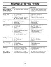
... grass, leaves, and trash around mandrels. 1. Poor grass discharge 1. Allow grass to idle for 30 seconds before mowing. 4. Level mower deck. 5. Blown fuse. 1. Freewheel control in transmission during shipment or servicing. 1. Air trapped in "disengaged" position. 2. Move ... and allow to dry before stopping engine. 28 Mower deck not level. 3. Clogged mower deck vent holes from buildup of grass, leaves, and trash under mower. 8. Level mower deck. 3. Clean underside of mower housing. 8. Worn/damaged mower drive belt. 3. Remove obstruction. 2. Engine speed...
... grass, leaves, and trash around mandrels. 1. Poor grass discharge 1. Allow grass to idle for 30 seconds before mowing. 4. Level mower deck. 5. Blown fuse. 1. Freewheel control in transmission during shipment or servicing. 1. Air trapped in "disengaged" position. 2. Move ... and allow to dry before stopping engine. 28 Mower deck not level. 3. Clogged mower deck vent holes from buildup of grass, leaves, and trash under mower. 8. Level mower deck. 3. Clean underside of mower housing. 8. Worn/damaged mower drive belt. 3. Remove obstruction. 2. Engine speed...
User Manual
Page 33
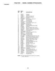
NO. inches 1 inch = 25.4 mm 33 CHASSIS TRACTOR - - MODEL NUMBER PPR20H42STA KEY PART NO. DESCRIPTION 1 174619 Chassis 2 176554 Drawbar 3 17060612 Screw 3/8-16 X .75 5 155272 Bumper Hood/Dash 9 168337X012 Dash P/L 10 72140608 Bolt Carriage 3/8-16 x 1 11 174996 ... Lh 34 179717X428 Footrest Pnt Rh 35 72110606 Bolt Rdhd Sht Sqnk 3/8-16 x 3/4 37 17490508 Screw Thdrol 6/16-18 x 1/2 TYT 38 175710 Bracket Asm Pivot Mower Rear 51 73800400 Nut Lock Hex W/Ins 1/4-20 52 19091416 Washer 9/32 x 7/8 x 16 Ga. 53 144697 Bracjet Grukke Lh 54 161464 Screw Hex Wshd 8-18...
NO. inches 1 inch = 25.4 mm 33 CHASSIS TRACTOR - - MODEL NUMBER PPR20H42STA KEY PART NO. DESCRIPTION 1 174619 Chassis 2 176554 Drawbar 3 17060612 Screw 3/8-16 X .75 5 155272 Bumper Hood/Dash 9 168337X012 Dash P/L 10 72140608 Bolt Carriage 3/8-16 x 1 11 174996 ... Lh 34 179717X428 Footrest Pnt Rh 35 72110606 Bolt Rdhd Sht Sqnk 3/8-16 x 3/4 37 17490508 Screw Thdrol 6/16-18 x 1/2 TYT 38 175710 Bracket Asm Pivot Mower Rear 51 73800400 Nut Lock Hex W/Ins 1/4-20 52 19091416 Washer 9/32 x 7/8 x 16 Ga. 53 144697 Bracjet Grukke Lh 54 161464 Screw Hex Wshd 8-18...
User Manual
Page 39
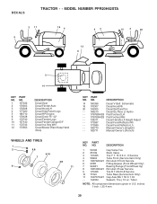
...9 170456 Tire R T 20x10-8 Service 10 7152J Tube Rear (Service Item Only) 11 104757X421 Cap Axle Blk 1 50 X 1 00 - - 144334 Sealant, Tire ( 10 oz. MODEL NUMBER PPR20H42STA 2 11 9 16 4 43 12 8 10 2 20 1 5 14 KEY NO. 1 2 3 4 5 8 9 10 11 12 PART NO. 157032 176303 176308 177020 180710 179128 172740 157140...Auto Decal Hood LH Decal Side Panel Logo Decal HP Engine Decal Deck "B" 42" Decal Fender Logo Decal Fender Danger E/F Decal Ins Strg Whl Decal Mower Warn Keep Hand Away KEY PART NO. Tube) NOTE: All component dimensions given in U.S. inches 1 inch = 25.4 mm 39 NO. NO. ...
...9 170456 Tire R T 20x10-8 Service 10 7152J Tube Rear (Service Item Only) 11 104757X421 Cap Axle Blk 1 50 X 1 00 - - 144334 Sealant, Tire ( 10 oz. MODEL NUMBER PPR20H42STA 2 11 9 16 4 43 12 8 10 2 20 1 5 14 KEY NO. 1 2 3 4 5 8 9 10 11 12 PART NO. 157032 176303 176308 177020 180710 179128 172740 157140...Auto Decal Hood LH Decal Side Panel Logo Decal HP Engine Decal Deck "B" 42" Decal Fender Logo Decal Fender Danger E/F Decal Ins Strg Whl Decal Mower Warn Keep Hand Away KEY PART NO. Tube) NOTE: All component dimensions given in U.S. inches 1 inch = 25.4 mm 39 NO. NO. ...


