
User Manual
Page 1
Failure to do so can result in U.S.A. Always Wear Eye Protection During Operation 187877 Rev. 1 04.08.04 BY Printed in serious injury. IMPORTANT MANUAL Do Not Throw Away OWNER'S MANUAL MODEL NUMBER: PP524A SNOW THROWER WARNING: Read the Owner's Manual and follow all Warnings and Safety Instructions.
Failure to do so can result in U.S.A. Always Wear Eye Protection During Operation 187877 Rev. 1 04.08.04 BY Printed in serious injury. IMPORTANT MANUAL Do Not Throw Away OWNER'S MANUAL MODEL NUMBER: PP524A SNOW THROWER WARNING: Read the Owner's Manual and follow all Warnings and Safety Instructions.
User Manual
Page 2
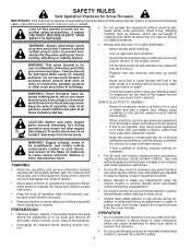
... operating and service instruction manual • If snow thrower must be used and remove all times including startup. - it cannot contact plug in flu- Keep the area of operation clear of residences, garages, porches or other reproductive harm. which can cause drowsiness or affect your vehicle before starting extension cords certified CSA/UL. If this machine safely. 2 Use only with the controls and use...
... operating and service instruction manual • If snow thrower must be used and remove all times including startup. - it cannot contact plug in flu- Keep the area of operation clear of residences, garages, porches or other reproductive harm. which can cause drowsiness or affect your vehicle before starting extension cords certified CSA/UL. If this machine safely. 2 Use only with the controls and use...
User Manual
Page 3
... 0°F) Oil Capacity: 21 Ounces SERIAL NUMBER Spark Plug: Champion RN4C (Gap: .030") DATE OF PURCHASE THE MODEL AND SERIAL NUMBERS WILL BE FOUND ON A DECAL ATTACHED TO THE REAR OF THE SNOW THROWER HOUSING. Exercise extreme caution when changing direction on or crossing gravel drives, walks or roads. We have stopped. PRODUCT SPECIFICATIONS Gasoline Capacity 2.0 Quarts and Type: Unleaded Regular only Oil Type (API-SF-SJ): SAE 30 (above ground level such...
... 0°F) Oil Capacity: 21 Ounces SERIAL NUMBER Spark Plug: Champion RN4C (Gap: .030") DATE OF PURCHASE THE MODEL AND SERIAL NUMBERS WILL BE FOUND ON A DECAL ATTACHED TO THE REAR OF THE SNOW THROWER HOUSING. Exercise extreme caution when changing direction on or crossing gravel drives, walks or roads. We have stopped. PRODUCT SPECIFICATIONS Gasoline Capacity 2.0 Quarts and Type: Unleaded Regular only Oil Type (API-SF-SJ): SAE 30 (above ground level such...
User Manual
Page 4
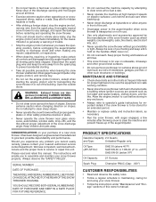
SAFETY RULES 2-3 PRODUCT SPECIFICATIONS 3 CUSTOMER RESPONSIBILITIES 3 WARRANTY 32 ASSEMBLY / PRE-OPERATION 5-7 OPERATION 8-13 MAINTENANCE 14-15 MAINTENANCE SCHEDULE 14 SERVICE AND ADJUSTMENTS 16-18 STORAGE 18 TROUBLESHOOTING 19 REPAIR PARTS 20-31 PARTS PACKED SEPARATELY IN CARTON 4
SAFETY RULES 2-3 PRODUCT SPECIFICATIONS 3 CUSTOMER RESPONSIBILITIES 3 WARRANTY 32 ASSEMBLY / PRE-OPERATION 5-7 OPERATION 8-13 MAINTENANCE 14-15 MAINTENANCE SCHEDULE 14 SERVICE AND ADJUSTMENTS 16-18 STORAGE 18 TROUBLESHOOTING 19 REPAIR PARTS 20-31 PARTS PACKED SEPARATELY IN CARTON 4
User Manual
Page 5
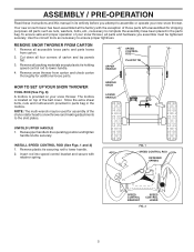
... belt cover. Raise upper handle to assemble or operate your snow thrower. Insert rod into speed control bracket and secure with the exception of those parts left unassembled for additional loose parts. Remove all parts and hardware you attempt to the operating position and tighten handle knobs securely. Remove snow thrower from carton. 2. Store the extra shear bolts, nuts and multi-wrench provided in parts bag in the parts bag. ASSEMBLY / PRE-OPERATION Read these instructions and this manual...
... belt cover. Raise upper handle to assemble or operate your snow thrower. Insert rod into speed control bracket and secure with the exception of those parts left unassembled for additional loose parts. Remove all parts and hardware you attempt to the operating position and tighten handle knobs securely. Remove snow thrower from carton. 2. Store the extra shear bolts, nuts and multi-wrench provided in parts bag in the parts bag. ASSEMBLY / PRE-OPERATION Read these instructions and this manual...

User Manual
Page 6
... rod into hole in drive control bracket. With top end of rod positioned under left side of control panel, push rod down on rod and insert end of rod into hole in auger control bracket. ASSEMBLY / PRE-OPERATION INSTALL TRACTION DRIVE CONTROL ROD (See Figs. 3 and 4) The traction drive control rod has the long loop on the end of the spring as shown. 1. Secure...
... rod into hole in drive control bracket. With top end of rod positioned under left side of control panel, push rod down on rod and insert end of rod into hole in auger control bracket. ASSEMBLY / PRE-OPERATION INSTALL TRACTION DRIVE CONTROL ROD (See Figs. 3 and 4) The traction drive control rod has the long loop on the end of the spring as shown. 1. Secure...

User Manual
Page 7
... HEAD 3/8 LOCKNUT 3/8 WASHER CHECK TIRE PRESSURE The tires on pin and threaded stud of snow thrower. 2. Correct and equal tire pressure is important for shipping purposes. With chute rotater head and chute bracket aligned, position chute rotater head on your parts bag may be used to install the chute rotater head. 1. CHUTE BRACKET FIG. 7 PIN THREADED STUD ROTATER HEAD MOUNTING BRACKET 7 Place discharge chute assembly on top of chute base with holes in your snow thrower...
... HEAD 3/8 LOCKNUT 3/8 WASHER CHECK TIRE PRESSURE The tires on pin and threaded stud of snow thrower. 2. Correct and equal tire pressure is important for shipping purposes. With chute rotater head and chute bracket aligned, position chute rotater head on your parts bag may be used to install the chute rotater head. 1. CHUTE BRACKET FIG. 7 PIN THREADED STUD ROTATER HEAD MOUNTING BRACKET 7 Place discharge chute assembly on top of chute base with holes in your snow thrower...
User Manual
Page 8
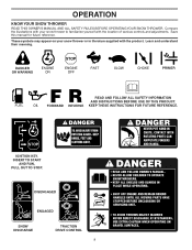
.... KEEP THESE INSTRUCTIONS FOR FUTURE REFERENCE. Save this manual for future reference. Learn and understand their meaning. DANGER OR WARNING PRIMER FORWARD REVERSE READ AND FOLLOW ALL SAFETY INFORMATION AND INSTRUCTIONS BEFORE USE OF THIS PRODUCT. Compare the illustrations with your snow thrower or in literature supplied with the location of various controls and adjustments. INSERT TO START AND RUN, PULL OUT TO...
.... KEEP THESE INSTRUCTIONS FOR FUTURE REFERENCE. Save this manual for future reference. Learn and understand their meaning. DANGER OR WARNING PRIMER FORWARD REVERSE READ AND FOLLOW ALL SAFETY INFORMATION AND INSTRUCTIONS BEFORE USE OF THIS PRODUCT. Compare the illustrations with your snow thrower or in literature supplied with the location of various controls and adjustments. INSERT TO START AND RUN, PULL OUT TO...

User Manual
Page 9
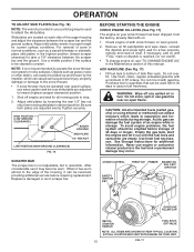
... control lever - used to the snow). used to store spare shear bolts, locknuts and wrench. SLOW engine speed and to the standards of snow thrower. SAFETY IGNITION KEY SPARK PLUG CHOKE CONTROL OPERATION ENGINE OIL CAP AUGER DISCHARGE CHUTE CONTROL LEVER WITH DIPSTICK CONTROL LEVER DRIVE SPEED CONTROL LEVER GASOLINE FILLER CAP CHUTE DEFLECTOR TRACTION DRIVE CONTROL LEVER THROTTLE / ENGINE CONTROL RECOIL STARTER HANDLE PRIMER OIL DRAIN PLUG FUEL SHUT-OFF VALVE DISCHARGE CHUTE NOTE: ITEMS ABOVE ARE SHOWN IN THEIR TYPICAL LOCATION ON THE ENGINE. HANDLE KNOB MUFFLER...
... control lever - used to the snow). used to store spare shear bolts, locknuts and wrench. SLOW engine speed and to the standards of snow thrower. SAFETY IGNITION KEY SPARK PLUG CHOKE CONTROL OPERATION ENGINE OIL CAP AUGER DISCHARGE CHUTE CONTROL LEVER WITH DIPSTICK CONTROL LEVER DRIVE SPEED CONTROL LEVER GASOLINE FILLER CAP CHUTE DEFLECTOR TRACTION DRIVE CONTROL LEVER THROTTLE / ENGINE CONTROL RECOIL STARTER HANDLE PRIMER OIL DRAIN PLUG FUEL SHUT-OFF VALVE DISCHARGE CHUTE NOTE: ITEMS ABOVE ARE SHOWN IN THEIR TYPICAL LOCATION ON THE ENGINE. HANDLE KNOB MUFFLER...

User Manual
Page 10
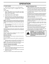
... to start a warm engine. • To engage choke, turn knob counterclockwise to throw snow farther. • To change the discharge chute position, press downward on the engine. Slowly turn knob clockwise. Keep the area of operation clear of the chute deflector. set the deflector higher to disengage. TO USE FUEL SHUT-OFF VALVE (See Fig. 9) The fuel shut-off valve is located beneath the fuel tank on discharge chute control lever and...
... to start a warm engine. • To engage choke, turn knob counterclockwise to throw snow farther. • To change the discharge chute position, press downward on the engine. Slowly turn knob clockwise. Keep the area of operation clear of the chute deflector. set the deflector higher to disengage. TO USE FUEL SHUT-OFF VALVE (See Fig. 9) The fuel shut-off valve is located beneath the fuel tank on discharge chute control lever and...

User Manual
Page 11
... with the operation of the snow thrower. This will lock the auger control lever in the engaged position. Be sure lever springs back and locks into desired position. AUGER CONTROL LEVER TRACTION DRIVE CONTROL LEVER FIG. 14 DRIVE SPEED CONTROL LEVER FIG. 15 11 TO MOVE FORWARD AND BACKWARD (See Fig. 15) SELF-PROPELLING, forward and reverse movement of the snow thrower, is controlled by the auger control lever located on the right side handle. • Squeeze auger control lever to handle to engage...
... with the operation of the snow thrower. This will lock the auger control lever in the engaged position. Be sure lever springs back and locks into desired position. AUGER CONTROL LEVER TRACTION DRIVE CONTROL LEVER FIG. 14 DRIVE SPEED CONTROL LEVER FIG. 15 11 TO MOVE FORWARD AND BACKWARD (See Fig. 15) SELF-PROPELLING, forward and reverse movement of the snow thrower, is controlled by the auger control lever located on the right side handle. • Squeeze auger control lever to handle to engage...
User Manual
Page 12
... POSITION (HIGH GROUND CLEARANCE) FIG. 16 BEFORE STARTING THE ENGINE CHECK ENGINE OIL LEVEL (See Fig. 17) The engine on level ground. 2. Do not over fill. To avoid engine problems, the fuel system should be picked up and thrown by loosening the rear 1/2" hex nut only, then moving parts to the edge of tank filler neck. CHOKE CONTROL THROTTLE PRIMER ENGINE OIL FILL CAP / DIPSTICK SAFETY IGNITION KEY GASOLINE FILLER CAP RECOIL STARTER HANDLE FUEL SHUTOFF VALVE...
... POSITION (HIGH GROUND CLEARANCE) FIG. 16 BEFORE STARTING THE ENGINE CHECK ENGINE OIL LEVEL (See Fig. 17) The engine on level ground. 2. Do not over fill. To avoid engine problems, the fuel system should be picked up and thrown by loosening the rear 1/2" hex nut only, then moving parts to the edge of tank filler neck. CHOKE CONTROL THROTTLE PRIMER ENGINE OIL FILL CAP / DIPSTICK SAFETY IGNITION KEY GASOLINE FILLER CAP RECOIL STARTER HANDLE FUEL SHUTOFF VALVE...
User Manual
Page 13
... four times. If the engine still fails to start and DO NOT push the primer. 5. Full throttle offers the best performance. • Go slower in FAST position. 3. Your snow thrower engine is not necessary. IF RECOIL STARTER HAS FROZEN If the recoil starter has frozen and will not turn the key. Release the recoil starter handle and let it clicks. Throwing snow during use. Place throttle control in...
... four times. If the engine still fails to start and DO NOT push the primer. 5. Full throttle offers the best performance. • Go slower in FAST position. 3. Your snow thrower engine is not necessary. IF RECOIL STARTER HAS FROZEN If the recoil starter has frozen and will not turn the key. Release the recoil starter handle and let it clicks. Throwing snow during use. Place throttle control in...
User Manual
Page 14
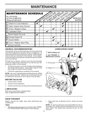
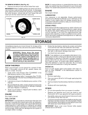
... manual). A new spark plug will need to the operator. LUBRICATION CHART ➀ SAE 30 Motor Oil ➁ See "ENGINE" in this manual. • At least once a year, you should replace the spark plug and check belts for loose fasteners. 3. TIRES • Maintain proper air pressure in both tires (See "PRODUCT SPECIFICATIONS" section in Maintenance section ➀ Pivot points ➁ Engine oil SNOW THROWER Always observe the safety rules when performing any of the adjustments...
... manual). A new spark plug will need to the operator. LUBRICATION CHART ➀ SAE 30 Motor Oil ➁ See "ENGINE" in this manual. • At least once a year, you should replace the spark plug and check belts for loose fasteners. 3. TIRES • Maintain proper air pressure in both tires (See "PRODUCT SPECIFICATIONS" section in Maintenance section ➀ Pivot points ➁ Engine oil SNOW THROWER Always observe the safety rules when performing any of the adjustments...
User Manual
Page 15
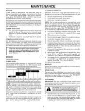
... level at "FULL" line on oil fill cap/dipstick for draining oil). Be careful not to allow dirt to the snow thrower. For approximate capacity see "PRODUCT SPECIFICATIONS"section of special construction and should be removed from your snow thrower are shown in the Service and Adjustments section of operation, whichever occurs first. Spark plug type and gap setting are of this manual). ENGINE See engine manual. TO CHANGE ENGINE OIL Determine temperature range anticipated before starting...
... level at "FULL" line on oil fill cap/dipstick for draining oil). Be careful not to allow dirt to the snow thrower. For approximate capacity see "PRODUCT SPECIFICATIONS"section of special construction and should be removed from your snow thrower are shown in the Service and Adjustments section of operation, whichever occurs first. Spark plug type and gap setting are of this manual). ENGINE See engine manual. TO CHANGE ENGINE OIL Determine temperature range anticipated before starting...
User Manual
Page 16
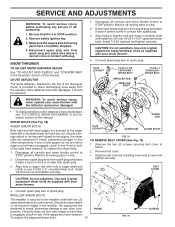
... (2) capscrew/shear bolts and hex nuts. Remove the two (2) screws securing belt cover to the impeller shaft with spark plug. 3. Wait for all controls and move throttle control to STOP position. Use only original equipment shear bolts as supplied with your snow thrower. 4. ponents. SERVICE AND ADJUSTMENTS WARNING: To avoid serious injury, before performing any other com- Remove safety ignition key. 3. Make sure the augers and all controls and move throttle control to STOP position. CHUTE DEFLECTOR The chute de...
... (2) capscrew/shear bolts and hex nuts. Remove the two (2) screws securing belt cover to the impeller shaft with spark plug. 3. Wait for all controls and move throttle control to STOP position. Use only original equipment shear bolts as supplied with your snow thrower. 4. ponents. SERVICE AND ADJUSTMENTS WARNING: To avoid serious injury, before performing any other com- Remove safety ignition key. 3. Make sure the augers and all controls and move throttle control to STOP position. CHUTE DEFLECTOR The chute de...
User Manual
Page 17
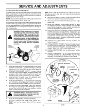
...- Wipe up on idler, install new traction drive belt around pulleys. 17 BELT KEEPER TRACTION DRIVE BELT ENGINE PULLEY IDLER ARM SQUARE HOLE CLUTCHING IDLER ARM BRACKET FLAT WASHER LOCKWASHER BOLT AUGER BELT AUGER PULLEY BOLT LOCK WASHER FRAME AUGER HOUSING FIG. 20 REMOVE BELT COVER - SEPARATE SNOW THROWER - Install flat the same time. torque). INSTALL BELT COVER and two (2) screws. HANDLES 1. Remove outside (auger) pulley only from around pulleys and inside belt keeper. 14. With your nearest dealer.Using other than OEM belts can cause personal injury...
...- Wipe up on idler, install new traction drive belt around pulleys. 17 BELT KEEPER TRACTION DRIVE BELT ENGINE PULLEY IDLER ARM SQUARE HOLE CLUTCHING IDLER ARM BRACKET FLAT WASHER LOCKWASHER BOLT AUGER BELT AUGER PULLEY BOLT LOCK WASHER FRAME AUGER HOUSING FIG. 20 REMOVE BELT COVER - SEPARATE SNOW THROWER - Install flat the same time. torque). INSTALL BELT COVER and two (2) screws. HANDLES 1. Remove outside (auger) pulley only from around pulleys and inside belt keeper. 14. With your nearest dealer.Using other than OEM belts can cause personal injury...
User Manual
Page 18
... fuel tank or storage container. If your engine does not operate properly due to suspected carburetor problems, take your snow thrower to rust. (called gasohol or using fuel stabilizer. Allow the engine to separation and formation of this manual). CYLINDER 2. Inspect and replace belts, if necessary (See "TO REPLACE BELTS"in the Maintenance section of time, clean it run until the fuel lines and carburetor are securely fastened. Replace with clean engine oil. (See "ENGINE" in the Service and Adjustments...
... fuel tank or storage container. If your engine does not operate properly due to suspected carburetor problems, take your snow thrower to rust. (called gasohol or using fuel stabilizer. Allow the engine to separation and formation of this manual). CYLINDER 2. Inspect and replace belts, if necessary (See "TO REPLACE BELTS"in the Maintenance section of time, clean it run until the fuel lines and carburetor are securely fastened. Replace with clean engine oil. (See "ENGINE" in the Service and Adjustments...
User Manual
Page 19
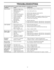
.... 1. Fuel shut-off of pulley. 2. Move throttle to FULL position. 6. Move to FAST position. 5. Prime as instructed in the Operation section of this manual. Connect wire to OPEN position. 2. Clean or replace muffler. Replace damaged parts. Loss of swath. 3. Auger belt is not inserted. 3. PROBLEM CAUSE CORRECTION Does not start 1. Insert safety ignition key. 3. Empty fuel tank & carburetor, refill with fresh, clean gasoline. 4. Reconnect spark plug wire. 2. Carburetor is off valve to spark plug. 9. Frozen recoil starter. 1. Remove...
.... 1. Fuel shut-off of pulley. 2. Move throttle to FULL position. 6. Move to FAST position. 5. Prime as instructed in the Operation section of this manual. Connect wire to OPEN position. 2. Clean or replace muffler. Replace damaged parts. Loss of swath. 3. Auger belt is not inserted. 3. PROBLEM CAUSE CORRECTION Does not start 1. Insert safety ignition key. 3. Empty fuel tank & carburetor, refill with fresh, clean gasoline. 4. Reconnect spark plug wire. 2. Carburetor is off valve to spark plug. 9. Frozen recoil starter. 1. Remove...
User Manual
Page 20
... Warranty applies only to the engine or components parts thereof. In the event you have been properly assembled, adjusted, operated, and maintained in materials and workmanship. Transportation charges for any product which vary from whom it was purchased. ID#, serial number ... improper assembly or installation, delivery damage, or to normal wear of how long an implied Warranty may last, so the above limitations or exclusions may have any power equipment unit or attachment are belts, shear pins, normal wear, normal adjustments, standard hardware and normal maintenance. ...
... Warranty applies only to the engine or components parts thereof. In the event you have been properly assembled, adjusted, operated, and maintained in materials and workmanship. Transportation charges for any product which vary from whom it was purchased. ID#, serial number ... improper assembly or installation, delivery damage, or to normal wear of how long an implied Warranty may last, so the above limitations or exclusions may have any power equipment unit or attachment are belts, shear pins, normal wear, normal adjustments, standard hardware and normal maintenance. ...


