
User Manual
Page 2
... all times including startup. - Never remove fuel tank cap or add fuel to a running (except when specifically allow children to lowest (highest scraper clearance) position. When practical, remove gas-powered equipment from the truck or trailer and refuel it on a trailer with extreme care. Know how to stop the to operate the equipment. BECOME ALERT!!! Do not use electric starting motors use snow thrower on clothing, change clothing...
... all times including startup. - Never remove fuel tank cap or add fuel to a running (except when specifically allow children to lowest (highest scraper clearance) position. When practical, remove gas-powered equipment from the truck or trailer and refuel it on a trailer with extreme care. Know how to stop the to operate the equipment. BECOME ALERT!!! Do not use electric starting motors use snow thrower on clothing, change clothing...
User Manual
Page 3
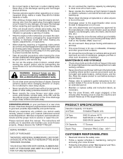
... visibility or light. PRODUCT SPECIFICATIONS Gasoline Capacity 3.5 Quarts and Type: Unleaded Regular only Oil Type (API-SF-SJ): SAE 30 (above ground level such as wheel weights, counterweights, cabs, tire chains, electric start to service or repair this owner's manual. 3 Look behind and use the snow thrower on or crossing gravel drives, walks or roads. It has been designed, engineered and manufactured to prevent accidental starting the engine (motor) and for hidden...
... visibility or light. PRODUCT SPECIFICATIONS Gasoline Capacity 3.5 Quarts and Type: Unleaded Regular only Oil Type (API-SF-SJ): SAE 30 (above ground level such as wheel weights, counterweights, cabs, tire chains, electric start to service or repair this owner's manual. 3 Look behind and use the snow thrower on or crossing gravel drives, walks or roads. It has been designed, engineered and manufactured to prevent accidental starting the engine (motor) and for hidden...
User Manual
Page 5
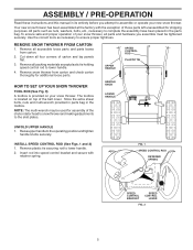
... the chute rotator head to snow thrower and making adjustments to ensure proper tightness. Your new snow thrower has been assembled at . 3. Raise upper handle to lower handle. 2. NOTE: The multi-wrench may be tightened securely. Remove plastic tie securing rod to the operating position and tighten handle knobs securely. Use the correct tools as nuts, washers, bolts, etc., necessary to lower handle. 4. Remove snow thrower from carton. 2. ASSEMBLY / PRE-OPERATION Read these instructions and this manual in...
... the chute rotator head to snow thrower and making adjustments to ensure proper tightness. Your new snow thrower has been assembled at . 3. Raise upper handle to lower handle. 2. NOTE: The multi-wrench may be tightened securely. Remove plastic tie securing rod to the operating position and tighten handle knobs securely. Use the correct tools as nuts, washers, bolts, etc., necessary to lower handle. 4. Remove snow thrower from carton. 2. ASSEMBLY / PRE-OPERATION Read these instructions and this manual in...

User Manual
Page 7
... the auger housing and the bar of auger housing as shown. 4. Place discharge chute assembly on your parts bag may be used to ride up on top of chute rotater head with holes in a location which does not cover the warning decals on hard, icy drifts. With chute rotater head and chute bracket aligned, position chute rotater head on pin and threaded stud of the auger housing to install the chute rotater head. 1. Shut off engine...
... the auger housing and the bar of auger housing as shown. 4. Place discharge chute assembly on your parts bag may be used to ride up on top of chute rotater head with holes in a location which does not cover the warning decals on hard, icy drifts. With chute rotater head and chute bracket aligned, position chute rotater head on pin and threaded stud of the auger housing to install the chute rotater head. 1. Shut off engine...

User Manual
Page 8
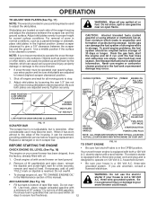
.... IGNITION KEY. DISENGAGED ENGAGED SNOW DISCHARGE TRACTION DRIVE CONTROL 8 Compare the illustrations with your snow thrower or in literature supplied with the location of various controls and adjustments. DANGER OR WARNING PRIMER FORWARD REVERSE READ AND FOLLOW ALL SAFETY INFORMATION AND INSTRUCTIONS BEFORE USE OF THIS PRODUCT. KEEP THESE INSTRUCTIONS FOR FUTURE REFERENCE. OPERATION KNOW YOUR SNOW THROWER READ THIS OWNER'S MANUAL AND ALL SAFETY RULES BEFORE OPERATING YOUR SNOW THROWER...
.... IGNITION KEY. DISENGAGED ENGAGED SNOW DISCHARGE TRACTION DRIVE CONTROL 8 Compare the illustrations with your snow thrower or in literature supplied with the location of various controls and adjustments. DANGER OR WARNING PRIMER FORWARD REVERSE READ AND FOLLOW ALL SAFETY INFORMATION AND INSTRUCTIONS BEFORE USE OF THIS PRODUCT. KEEP THESE INSTRUCTIONS FOR FUTURE REFERENCE. OPERATION KNOW YOUR SNOW THROWER READ THIS OWNER'S MANUAL AND ALL SAFETY RULES BEFORE OPERATING YOUR SNOW THROWER...

User Manual
Page 9
...Choke Control - used to the standards of snow thrower. SAFETY IGNITION KEY SPARK PLUG CHOKE CONTROL OPERATION ENGINE OIL CAP AUGER DISCHARGE CHUTE CONTROL LEVER WITH DIPSTICK CONTROL LEVER DRIVE SPEED CONTROL LEVER GASOLINE FILLER CAP CHUTE DEFLECTOR TRACTION DRIVE CONTROL LEVER THROTTLE / ENGINE CONTROL OIL DRAIN PLUG RECOIL (AUXILIARY) STARTER HANDLE POWER CORD PLUG ELECTRIC START BUTTON FUEL SHUT-OFF VALVE PRIMER DISCHARGE CHUTE NOTE: ITEMS ABOVE ARE SHOWN IN THEIR TYPICAL LOCATION ON THE ENGINE. Traction drive control lever - Electric start and run. used...
...Choke Control - used to the standards of snow thrower. SAFETY IGNITION KEY SPARK PLUG CHOKE CONTROL OPERATION ENGINE OIL CAP AUGER DISCHARGE CHUTE CONTROL LEVER WITH DIPSTICK CONTROL LEVER DRIVE SPEED CONTROL LEVER GASOLINE FILLER CAP CHUTE DEFLECTOR TRACTION DRIVE CONTROL LEVER THROTTLE / ENGINE CONTROL OIL DRAIN PLUG RECOIL (AUXILIARY) STARTER HANDLE POWER CORD PLUG ELECTRIC START BUTTON FUEL SHUT-OFF VALVE PRIMER DISCHARGE CHUTE NOTE: ITEMS ABOVE ARE SHOWN IN THEIR TYPICAL LOCATION ON THE ENGINE. Traction drive control lever - Electric start and run. used...

User Manual
Page 10
... change the discharge chute position, press downward on the engine.Always operate the snow thrower with the fuel shut-off valve is located on the engine. DISCHARGE CHUTE CONTROL LEVER FAST SLOW FIG. 11 FIG. 13 The DISTANCE that snow is thrown is controlled by the position of the chute deflector. set the deflector higher to start a warm engine. • To engage choke, turn knob counterclockwise to stop . Slowly turn knob clockwise. Set...
... change the discharge chute position, press downward on the engine.Always operate the snow thrower with the fuel shut-off valve is located on the engine. DISCHARGE CHUTE CONTROL LEVER FAST SLOW FIG. 11 FIG. 13 The DISTANCE that snow is thrown is controlled by the position of the chute deflector. set the deflector higher to start a warm engine. • To engage choke, turn knob counterclockwise to stop . Slowly turn knob clockwise. Set...

User Manual
Page 11
... drive speed control lever. • Press downward on the speed control lever and move speed control lever when traction drive control lever is engaged. This will lock the auger control lever in the engaged position. Damage to the snow thrower can result. • Slower speeds are for light snow and transporting the snow thrower. OPERATION HIGH POSITION KNOB CHUTE DEFLECTOR LOW POSITION FIG. 14 TO THROW SNOW (See Fig. 15) The auger rotation is controlled by the auger control lever located on the right side handle. • Squeeze auger control lever...
... drive speed control lever. • Press downward on the speed control lever and move speed control lever when traction drive control lever is engaged. This will lock the auger control lever in the engaged position. Damage to the snow thrower can result. • Slower speeds are for light snow and transporting the snow thrower. OPERATION HIGH POSITION KNOB CHUTE DEFLECTOR LOW POSITION FIG. 14 TO THROW SNOW (See Fig. 15) The auger rotation is controlled by the auger control lever located on the right side handle. • Squeeze auger control lever...
User Manual
Page 12
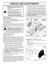
... 1/2" hex nut only, then moving parts to desired position. Use fresh fuel next season. CHOKE CONTROL THROTTLE PRIMER ENGINE OIL FILL CAP / DIPSTICK SAFETY IGNITION KEY AUGER HOUSING SKID PLATE 1/2" HEX NUT LOW POSITION (HIGH GROUND CLEARANCE) GASOLINE FILLER CAP SCRAPER BAR FIG. 17 The scraper bar is not adjustable, but is a 120 Volt A.C. Replace a damaged or worn scraper bar. BEFORE STARTING THE ENGINE CHECK ENGINE OIL LEVEL (See Fig. 18) The engine on your parts bag may occur. Check engine oil with snow thrower on dipstick...
... 1/2" hex nut only, then moving parts to desired position. Use fresh fuel next season. CHOKE CONTROL THROTTLE PRIMER ENGINE OIL FILL CAP / DIPSTICK SAFETY IGNITION KEY AUGER HOUSING SKID PLATE 1/2" HEX NUT LOW POSITION (HIGH GROUND CLEARANCE) GASOLINE FILLER CAP SCRAPER BAR FIG. 17 The scraper bar is not adjustable, but is a 120 Volt A.C. Replace a damaged or worn scraper bar. BEFORE STARTING THE ENGINE CHECK ENGINE OIL LEVEL (See Fig. 18) The engine on your parts bag may occur. Check engine oil with snow thrower on dipstick...

User Manual
Page 13
... engine clean and clear of the starter, proceed as possible. 2. Throwing snow during use primer when starting . ELECTRIC STARTER 1. Pull recoil starter handle quickly. See "TO ADJUST SKID PLATES" in FAST position. 3. NOTE: Do not use . Wait 5 to start and DO NOT push the primer. 5. DO NOT turn the key. Do not allow engine to remove snow immediately after each attempt. Full throttle offers the best performance. • Go slower in FAST position. 3. OPERATION...
... engine clean and clear of the starter, proceed as possible. 2. Throwing snow during use primer when starting . ELECTRIC STARTER 1. Pull recoil starter handle quickly. See "TO ADJUST SKID PLATES" in FAST position. 3. NOTE: Do not use . Wait 5 to start and DO NOT push the primer. 5. DO NOT turn the key. Do not allow engine to remove snow immediately after each attempt. Full throttle offers the best performance. • Go slower in FAST position. 3. OPERATION...
User Manual
Page 14
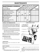
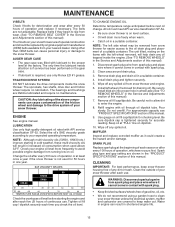
Check controls to slow leaks, tire sealant may be purchased from the warranty, operator must maintain snow thrower as instructed in Maintenance section ➀ Pivot points ➁ Engine oil LUBRICATION Keep your snow thrower well lubricated (See "LUBRICATION CHART"). TIRES • Maintain proper air pressure in both tires (See "PRODUCT SPECIFICATIONS" section in this manual. All adjustments in the Service and Adjustments section of injury to the operator. A new spark plug will need to be...
Check controls to slow leaks, tire sealant may be purchased from the warranty, operator must maintain snow thrower as instructed in Maintenance section ➀ Pivot points ➁ Engine oil LUBRICATION Keep your snow thrower well lubricated (See "LUBRICATION CHART"). TIRES • Maintain proper air pressure in both tires (See "PRODUCT SPECIFICATIONS" section in this manual. All adjustments in the Service and Adjustments section of injury to the operator. A new spark plug will need to be...
User Manual
Page 15
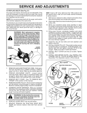
... if the snow thrower is required, use . WARNING: Disconnect spark plug wire from spark plug and place wire where it cannot come in a suitable container. Replace belts if they begin to the snow thrower. TheV-belts on oil. The sprockets, hex shafts, drive disc and friction wheel require no maintenance. The unit tilted, resting on oil fill cap/dipstick for checking level. Install drain plug and tighten securely. 5. Refill engine with API service classifi...
... if the snow thrower is required, use . WARNING: Disconnect spark plug wire from spark plug and place wire where it cannot come in a suitable container. Replace belts if they begin to the snow thrower. TheV-belts on oil. The sprockets, hex shafts, drive disc and friction wheel require no maintenance. The unit tilted, resting on oil fill cap/dipstick for checking level. Install drain plug and tighten securely. 5. Refill engine with API service classifi...
User Manual
Page 16
... this manual. Install 1/4-20 lock nut and tighten securely. To replace the capscrew/shear bolts: 16 FRAME FIG. 20 SCREWS Remove safety ignition key. 3. To replace the shear bolts: 1. AUGER HUB 1/4-20 LOCKNUT AUGER HUB AUGER SHAFT FIG. 19 TO REMOVE BELT COVER (See Fig. 20) 1. Disconnect spark plug wire from the operator. SNOW THROWER TO ADJUST SNOW THROWER HEIGHT See "TO ADJUST SKID PLATES" and "SCRAPER BAR" in impeller shaft and install two (2) new 1/4-20 x 1-5/8" capscrew/shear bolts. CAUTION: Do not substitute. Be sure throttle is...
... this manual. Install 1/4-20 lock nut and tighten securely. To replace the capscrew/shear bolts: 16 FRAME FIG. 20 SCREWS Remove safety ignition key. 3. To replace the shear bolts: 1. AUGER HUB 1/4-20 LOCKNUT AUGER HUB AUGER SHAFT FIG. 19 TO REMOVE BELT COVER (See Fig. 20) 1. Disconnect spark plug wire from the operator. SNOW THROWER TO ADJUST SNOW THROWER HEIGHT See "TO ADJUST SKID PLATES" and "SCRAPER BAR" in impeller shaft and install two (2) new 1/4-20 x 1-5/8" capscrew/shear bolts. CAUTION: Do not substitute. Be sure throttle is...
User Manual
Page 17
... the same time. WARNING: As the last bolt is inside belt keepers. 9. TheV-belts on the auger belt and squeeze sides together above pulley so belt is important that the belt(s) be replaced by a qualified service center. FRAME ASSEMBLY AUGER HOUSING HINT: Insert a 3/8" drive ratchet (in the operating position holding the handles, remove the two (2) bolts and lock washers holding auger housing and frame together. Bring snow thrower completely together and check carefully for...
... the same time. WARNING: As the last bolt is inside belt keepers. 9. TheV-belts on the auger belt and squeeze sides together above pulley so belt is important that the belt(s) be replaced by a qualified service center. FRAME ASSEMBLY AUGER HOUSING HINT: Insert a 3/8" drive ratchet (in the operating position holding the handles, remove the two (2) bolts and lock washers holding auger housing and frame together. Bring snow thrower completely together and check carefully for...
User Manual
Page 18
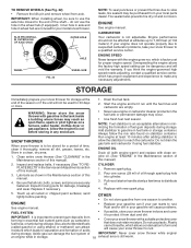
... (2,134 meters). If your engine does not operate properly due to suspected carburetor problems, take your snow thrower to distribute oil. 4. If you think the engine-governed high speed needs adjusting, contact a qualified service center, which leads to rust. Store in the wheel hub (if equipped). Pour one season to reach the carburetor. Pull recoil starter handle slowly a few times to a qualified service center. OTHER •...
... (2,134 meters). If your engine does not operate properly due to suspected carburetor problems, take your snow thrower to distribute oil. 4. If you think the engine-governed high speed needs adjusting, contact a qualified service center, which leads to rust. Store in the wheel hub (if equipped). Pour one season to reach the carburetor. Pull recoil starter handle slowly a few times to a qualified service center. OTHER •...
User Manual
Page 19
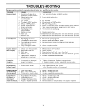
... Loose parts or damaged augers or impeller. 1. Recoil starter is flooded. 8. of power 1. Choke in need of adjustment or overhaul. 1. Engine is hard to OFF position. 2. Bad spark plug. 10. Remove ice and snow on and around fuel tank cap. 4. Tighten all fasteners. Auger belt is worn. 3. Auger belt is off valve to FULL position. 6. Check / replace auger belt. 3. Primer not depressed. 7. Water in the Operation section of pulley. 2. Insert safety ignition key. 3. Prime as instructed in fuel. 1. Replace spark plug. 10. Loss of drive speed...
... Loose parts or damaged augers or impeller. 1. Recoil starter is flooded. 8. of power 1. Choke in need of adjustment or overhaul. 1. Engine is hard to OFF position. 2. Bad spark plug. 10. Remove ice and snow on and around fuel tank cap. 4. Tighten all fasteners. Auger belt is worn. 3. Auger belt is off valve to FULL position. 6. Check / replace auger belt. 3. Primer not depressed. 7. Water in the Operation section of pulley. 2. Insert safety ignition key. 3. Prime as instructed in fuel. 1. Replace spark plug. 10. Loss of drive speed...
User Manual
Page 21
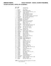
inches 1 inch = 25.4 mm 21 REPAIR PARTS SNOW THROWER - NO. MODEL NUMBER P524ESA AUGER HOUSING / IMPELLER ASSEMBLY KEY PART NO. DESCRIPTION 1 183578 Bag, Weight 2 183577 Bracket, Weight Bag 3 74520524 Screw, Hex Head 5/16-18 x 1-1/2 4 181083 Pulley, Impeller 5 175323 Bearing Assembly, Flange 6 155377 Nut, Hex Flange 5/16-18 7 180355 Bolt, Flat Head, Carriage 5/16-18 x 5/8 8 72270505 Bolt, Carriage 5/16-18 x 5/8 9 178820 Nut, Cage 3/8-16 10 175309X428 Housing, Auger 11 174838X479 Bar, Scraper 12 178675X008 Bracket, Corner Discharge...
inches 1 inch = 25.4 mm 21 REPAIR PARTS SNOW THROWER - NO. MODEL NUMBER P524ESA AUGER HOUSING / IMPELLER ASSEMBLY KEY PART NO. DESCRIPTION 1 183578 Bag, Weight 2 183577 Bracket, Weight Bag 3 74520524 Screw, Hex Head 5/16-18 x 1-1/2 4 181083 Pulley, Impeller 5 175323 Bearing Assembly, Flange 6 155377 Nut, Hex Flange 5/16-18 7 180355 Bolt, Flat Head, Carriage 5/16-18 x 5/8 8 72270505 Bolt, Carriage 5/16-18 x 5/8 9 178820 Nut, Cage 3/8-16 10 175309X428 Housing, Auger 11 174838X479 Bar, Scraper 12 178675X008 Bracket, Corner Discharge...
User Manual
Page 27
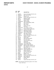
..., Rubber Wheel 19 73930500 Nut, Lock 5/16-18 20 178613 Hub, Rubber Wheel 21 74760514 Screw, Hex Head 5/16-18 x 7/8 22 85179 Retainer, Hairpin 23 180135 Spring, Bias 24 180081 Gear, Axle (58 Teeth) 25 178695 Pin, Pivot Lever 26 175341 Plate Assembly, Drive 27 179352 Shaft, Axle 28 175340 Shaft, Short Hex 29 175350X479 Lever, Shifter Plate 30 175349X479 Bracket, Shifter Support 31 72270505 Bolt, Carriage...
..., Rubber Wheel 19 73930500 Nut, Lock 5/16-18 20 178613 Hub, Rubber Wheel 21 74760514 Screw, Hex Head 5/16-18 x 7/8 22 85179 Retainer, Hairpin 23 180135 Spring, Bias 24 180081 Gear, Axle (58 Teeth) 25 178695 Pin, Pivot Lever 26 175341 Plate Assembly, Drive 27 179352 Shaft, Axle 28 175340 Shaft, Short Hex 29 175350X479 Lever, Shifter Plate 30 175349X479 Bracket, Shifter Support 31 72270505 Bolt, Carriage...
User Manual
Page 31
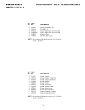
inches 1 inch = 25.4 mm KEY PART NO. MODEL NUMBER P524ESA KEY PART NO. REPAIR PARTS WHEELS / DECALS SNOW THROWER - NO. 1 181037 2 185126 3 181035 4 181042 5 183879 6 181033 7 155798 8 155800 9 181039 - - 185156 - - 185158 DESCRIPTION Decal, Danger Decal, Poulan, 5.5HP/24" Decal, Danger, Deflector Decal, Danger Decal, Poulan Decal, Instruction Decal, Traction Lever Decal, Auger Lever Decal, Speed Control Owner's Manual, English Owner's Manual, French NOTE: All component dimensions given in U.S. inches 1 inch = 25.4 mm 31 NO. 1 179264...
inches 1 inch = 25.4 mm KEY PART NO. MODEL NUMBER P524ESA KEY PART NO. REPAIR PARTS WHEELS / DECALS SNOW THROWER - NO. 1 181037 2 185126 3 181035 4 181042 5 183879 6 181033 7 155798 8 155800 9 181039 - - 185156 - - 185158 DESCRIPTION Decal, Danger Decal, Poulan, 5.5HP/24" Decal, Danger, Deflector Decal, Danger Decal, Poulan Decal, Instruction Decal, Traction Lever Decal, Auger Lever Decal, Speed Control Owner's Manual, English Owner's Manual, French NOTE: All component dimensions given in U.S. inches 1 inch = 25.4 mm 31 NO. 1 179264...

User Manual
Page 32
..., improper assembly or installation, delivery damage, or to the applicable manufacturer's warranty on these items. 2. This Warranty does not apply to any power equipment unit or attachment are belts, shear pins, normal wear, normal adjustments, standard hardware and normal maintenance. 6. Exclusions: Excluded from locale to an authorized service dealer. Please refer to normal wear of any product which we will repair or replace, at...
..., improper assembly or installation, delivery damage, or to the applicable manufacturer's warranty on these items. 2. This Warranty does not apply to any power equipment unit or attachment are belts, shear pins, normal wear, normal adjustments, standard hardware and normal maintenance. 6. Exclusions: Excluded from locale to an authorized service dealer. Please refer to normal wear of any product which we will repair or replace, at...


