
User Manual
Page 2
... on a trailer with care; Do not operate the equipment without proper instruction. 3. Do not put hands or feet near or under rotating parts. it is generally a warning of all units with electric drive motors or electric starting motors. 4. Stay alert for all persons, particularly small... as specified by manufacturer). 8. Do not use of the discharge opening at all times. 4. CAUTION: Muffler and other engine parts become extremely hot during operation or while performing an adjustment or repair to observe the following safety instructions could result in the manual...
... on a trailer with care; Do not operate the equipment without proper instruction. 3. Do not put hands or feet near or under rotating parts. it is generally a warning of all units with electric drive motors or electric starting motors. 4. Stay alert for all persons, particularly small... as specified by manufacturer). 8. Do not use of the discharge opening at all times. 4. CAUTION: Muffler and other engine parts become extremely hot during operation or while performing an adjustment or repair to observe the following safety instructions could result in the manual...
User Manual
Page 3
... 3 ASSEMBLY / PRE-OPERATION 4-6 OPERATION 7-12 MAINTENANCE SCHEDULE 13 MAINTENANCE 13-14 SERVICE AND ADJUSTMENTS 15-17 STORAGE 18 TROUBLESHOOTING 19 REPAIR PARTS 20-37 WARRANTY BACK PAGE 3 SERIAL NUMBER DATE OF PURCHASE THE MODEL AND SERIAL NUMBERS WILL BE FOUND ON A DECAL ATTACHED TO THE...this manual. When cleaning, repairing or inspecting the snow thrower, stop the engine and make certain the collector/impeller and all moving parts have competent, well-trained technicians and the proper tools to clean out the discharge chute. Never operate the machine at too fast ...
... 3 ASSEMBLY / PRE-OPERATION 4-6 OPERATION 7-12 MAINTENANCE SCHEDULE 13 MAINTENANCE 13-14 SERVICE AND ADJUSTMENTS 15-17 STORAGE 18 TROUBLESHOOTING 19 REPAIR PARTS 20-37 WARRANTY BACK PAGE 3 SERIAL NUMBER DATE OF PURCHASE THE MODEL AND SERIAL NUMBERS WILL BE FOUND ON A DECAL ATTACHED TO THE...this manual. When cleaning, repairing or inspecting the snow thrower, stop the engine and make certain the collector/impeller and all moving parts have competent, well-trained technicians and the proper tools to clean out the discharge chute. Never operate the machine at too fast ...

User Manual
Page 4
... SNOW THROWER TOOL BOX (See Fig. 10) REMOVE SNOW THROWER FROM CARTON 1. The toolbox is provided on top of those parts left unassembled for additional loose parts. Reading the entire manual will familiarize you with the exception of the belt cover. Store the extra shear bolts, nuts and...the pallet. 4. To ensure safe and proper operation of your snow thrower, all four corners of the product. Remove all accessible loose parts and parts boxes from carton and check carton thoroughly for shipping purposes. Use the correct tools as nuts, washers, bolts, etc., necessary to the ...
... SNOW THROWER TOOL BOX (See Fig. 10) REMOVE SNOW THROWER FROM CARTON 1. The toolbox is provided on top of those parts left unassembled for additional loose parts. Reading the entire manual will familiarize you with the exception of the belt cover. Store the extra shear bolts, nuts and...the pallet. 4. To ensure safe and proper operation of your snow thrower, all four corners of the product. Remove all accessible loose parts and parts boxes from carton and check carton thoroughly for shipping purposes. Use the correct tools as nuts, washers, bolts, etc., necessary to the ...

User Manual
Page 5
Additional carriage bolts, washers and handle knobs are in handles. Install in lower holes in bag of parts. Insert rod into hole in traction drive control lever. With top end of rod positioned under left side of control panel, push rod down . Snap ...
Additional carriage bolts, washers and handle knobs are in handles. Install in lower holes in bag of parts. Insert rod into hole in traction drive control lever. With top end of rod positioned under left side of control panel, push rod down . Snap ...

User Manual
Page 6
... discharge opening toward front of chute base with holes in your snow thrower were overinflated at right control lever. 3. Place discharge chute assembly on your parts bag may be used to install the chute rotator head. 1. If necessary, rotate chute assembly to align square and pin on the snow thrower. 1. Install...
... discharge opening toward front of chute base with holes in your snow thrower were overinflated at right control lever. 3. Place discharge chute assembly on your parts bag may be used to install the chute rotator head. 1. If necessary, rotate chute assembly to align square and pin on the snow thrower. 1. Install...

User Manual
Page 9
.... Set the deflector low to unclog the chute and/or auger. TO CONTROL SNOW DISCHARGE (See Figs. 11 & 12) WARNING: Snow throwers have exposed rotating parts, which snow is to stop the forward or reverse movement of the snow thrower. Use the clean-out tool, NOT YOUR HANDS, to throw snow... • Release traction drive control lever to "OFF" position. 2. Always operate the snow thrower with the fuel shut-off engine and wait for all moving parts to be thrown is controlled by the discharge chute control lever. • To change the discharge chute position, press down-
.... Set the deflector low to unclog the chute and/or auger. TO CONTROL SNOW DISCHARGE (See Figs. 11 & 12) WARNING: Snow throwers have exposed rotating parts, which snow is to stop the forward or reverse movement of the snow thrower. Use the clean-out tool, NOT YOUR HANDS, to throw snow... • Release traction drive control lever to "OFF" position. 2. Always operate the snow thrower with the fuel shut-off engine and wait for all moving parts to be thrown is controlled by the discharge chute control lever. • To change the discharge chute position, press down-

User Manual
Page 10
...In certain snow conditions, the discharge chute may be cleared is engaged. It is recommended that you use a slower speed until you to release your parts bag may become clogged with the operation of the snow thrower. Skid plates are in a safe direction (no vehicles, buildings, people, or other...Use a middle position if the surface to be used to adjust the skid plates. When cleaning, repairing, or inspecting, make certain all moving parts have stopped. Grasp the tool firmly by the handle and push and twist the tool into desired position. FIG. 14 10 AUGER CONTROL LEVER ...
...In certain snow conditions, the discharge chute may be cleared is engaged. It is recommended that you use a slower speed until you to release your parts bag may become clogged with the operation of the snow thrower. Skid plates are in a safe direction (no vehicles, buildings, people, or other...Use a middle position if the surface to be used to adjust the skid plates. When cleaning, repairing, or inspecting, make certain all moving parts have stopped. Grasp the tool firmly by the handle and push and twist the tool into desired position. FIG. 14 10 AUGER CONTROL LEVER ...
User Manual
Page 11
... replacement. Objects such as gravel, rocks or other debris, can easily be picked up and thrown by loosening the rear 1/2" hex nut only, then moving parts to the snow thrower. • If snow thrower must be operated over gravel or rocky surfaces. Adjust skid plates by the impeller, which leads to...
... replacement. Objects such as gravel, rocks or other debris, can easily be picked up and thrown by loosening the rear 1/2" hex nut only, then moving parts to the snow thrower. • If snow thrower must be operated over gravel or rocky surfaces. Adjust skid plates by the impeller, which leads to...
User Manual
Page 13
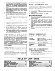
A new spark plug will need to be made periodically to properly maintain your nearest dealer. NOTE: Use only Original Equipment Manufacturer (OEM) parts to slip from wear. (See "TO REMOVE BELT COVER" in this manual). LUBRICATION CHART SAE 5W-30 Motor Oil See "ENGINE" in...SNOW THROWER Engine oil Always observe the safety rules when performing any BELTS maintenance. The belts are functioning properly. rubber. Using other local parts dealer. To receive full value from your snow thrower. Tire sealant also prevents tire dry rot than OEM belts can cause the unit to...
A new spark plug will need to be made periodically to properly maintain your nearest dealer. NOTE: Use only Original Equipment Manufacturer (OEM) parts to slip from wear. (See "TO REMOVE BELT COVER" in this manual). LUBRICATION CHART SAE 5W-30 Motor Oil See "ENGINE" in...SNOW THROWER Engine oil Always observe the safety rules when performing any BELTS maintenance. The belts are functioning properly. rubber. Using other local parts dealer. To receive full value from your snow thrower. Tire sealant also prevents tire dry rot than OEM belts can cause the unit to...

User Manual
Page 15
... "TO CONTROL SNOW DISCHARGE" in the impeller, the capscrews are secured to the impeller shaft with spark plug. 3. Wait for all moving parts have completely stopped. 4. CAUTION: Do not substitute. Insert safety ignition key and reconnect spark plug wire to frame. 2. Should a foreign object...locknuts and tighten securely. Remove belt cover. • Replace belt cover by installing cover and tightening screws. 4. Wait for all moving parts to any other components. Make sure the augers and all controls and move throttle control to direct discharging snow away from spark plug ...
... "TO CONTROL SNOW DISCHARGE" in the impeller, the capscrews are secured to the impeller shaft with spark plug. 3. Wait for all moving parts have completely stopped. 4. CAUTION: Do not substitute. Insert safety ignition key and reconnect spark plug wire to frame. 2. Should a foreign object...locknuts and tighten securely. Remove belt cover. • Replace belt cover by installing cover and tightening screws. 4. Wait for all moving parts to any other components. Make sure the augers and all controls and move throttle control to direct discharging snow away from spark plug ...
User Manual
Page 17
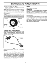
... any necessary adjustments. ENGINE SPEED Never tamper with the engine governor, which has the proper equipment and experience to suspected carburetor problems, take your local parts dealer.
... any necessary adjustments. ENGINE SPEED Never tamper with the engine governor, which has the proper equipment and experience to suspected carburetor problems, take your local parts dealer.
User Manual
Page 18
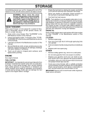
...a safe place. • Do not store gasoline from forming in the Maintenance section of oil through spark plug hole into cylinder. 3. Inspect moving parts for damage, breakage and wear. Touch up all nuts, bolts, screws, and pins are empty. • Never use plastic. Also, alcohol blended...2. OTHER • Remove safety ignition key; WARNING: Never store the snow thrower with clean engine oil. (See "ENGINE" in essential fuel system parts such as on stabilizer container. Allow the engine to cool before painting. Inspect and replace belts, if necessary (See "TO REPLACE BELTS" in fuel...
...a safe place. • Do not store gasoline from forming in the Maintenance section of oil through spark plug hole into cylinder. 3. Inspect moving parts for damage, breakage and wear. Touch up all nuts, bolts, screws, and pins are empty. • Never use plastic. Also, alcohol blended...2. OTHER • Remove safety ignition key; WARNING: Never store the snow thrower with clean engine oil. (See "ENGINE" in essential fuel system parts such as on stabilizer container. Allow the engine to cool before painting. Inspect and replace belts, if necessary (See "TO REPLACE BELTS" in fuel...
User Manual
Page 19
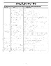
... of this manual. Turn fuel shut-off of this manual. 7. Replace spark plug. 10. Loss of traction 1. Water in fuel. 1. Loose parts or damaged augers or impeller. 1. Replace damaged parts. See "IF RECOIL STARTER HAS FROZEN" in the Operation section of pulley. 2. Check / replace drive belt. Loss of snow discharge or slowing...
... of this manual. Turn fuel shut-off of this manual. 7. Replace spark plug. 10. Loss of traction 1. Water in fuel. 1. Loose parts or damaged augers or impeller. 1. Replace damaged parts. See "IF RECOIL STARTER HAS FROZEN" in the Operation section of pulley. 2. Check / replace drive belt. Loss of snow discharge or slowing...
User Manual
Page 20
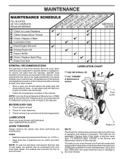
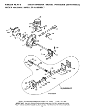
MODEL P14530ES (96198004502) AUGER HOUSING / IMPELLER ASSEMBLY 5 15 14 4 11 6 11 16 12 13 11 3 12 10 11 7 8 17 1 9 37 2 9 9 33 37 32 34 30 31 31 29 28 26 27 36 20 21 23 22 25 35 24 23 22 21 18 19 2 (EXPLODED) 01.07.026-F NOTE: All component dimensions given in U.S. Failure to do so could be hazardous, damage your snow thrower and void your warranty. 20 inches. 1 inch = 25.4 mm IMPORTANT: Use only Original Equipment Manufacturer (O.E.M.) replacement parts. REPAIR PARTS SNOW THROWER -
MODEL P14530ES (96198004502) AUGER HOUSING / IMPELLER ASSEMBLY 5 15 14 4 11 6 11 16 12 13 11 3 12 10 11 7 8 17 1 9 37 2 9 9 33 37 32 34 30 31 31 29 28 26 27 36 20 21 23 22 25 35 24 23 22 21 18 19 2 (EXPLODED) 01.07.026-F NOTE: All component dimensions given in U.S. Failure to do so could be hazardous, damage your snow thrower and void your warranty. 20 inches. 1 inch = 25.4 mm IMPORTANT: Use only Original Equipment Manufacturer (O.E.M.) replacement parts. REPAIR PARTS SNOW THROWER -

User Manual
Page 21
MODEL P14530ES (96198004502) AUGER HOUSING / IMPELLER ASSEMBLY KEY NO. 1 2 3 4 5 6 7 8 9 10 11 12 13 14 15 16 17 18 19 20 21 22 23 24 25 26 27 28 29 30 31 32 33 34 35 36 37 PART NO. 532 18 41-05 532 42 71-48 532 18 89-09 532 42... 5/16-18 X .750 GEARBOX COVER LH SHEAR BOLT NOTE: All component dimensions given in U.S. inches. 1 inch = 25.4 mm IMPORTANT: Use only Original Equipment Manufacturer (O.E.M.) replacement parts. Failure to do so could be hazardous, damage your snow thrower and void your warranty. 21 REPAIR...
MODEL P14530ES (96198004502) AUGER HOUSING / IMPELLER ASSEMBLY KEY NO. 1 2 3 4 5 6 7 8 9 10 11 12 13 14 15 16 17 18 19 20 21 22 23 24 25 26 27 28 29 30 31 32 33 34 35 36 37 PART NO. 532 18 41-05 532 42 71-48 532 18 89-09 532 42... 5/16-18 X .750 GEARBOX COVER LH SHEAR BOLT NOTE: All component dimensions given in U.S. inches. 1 inch = 25.4 mm IMPORTANT: Use only Original Equipment Manufacturer (O.E.M.) replacement parts. Failure to do so could be hazardous, damage your snow thrower and void your warranty. 21 REPAIR...

User Manual
Page 22
... snow thrower and void your warranty. 22 inches. 1 inch = 25.4 mm IMPORTANT: Use only Original Equipment Manufacturer (O.E.M.) replacement parts. MODEL P14530ES (96198004502) AUGER HOUSING / IMPELLER ASSEMBLY 1 3 (5x) 4 (5x) 2 01.07.003-A KEY NO. 1 2 3 4 PART NO. 532 41 52-91 532 40 76-45 872 27 05-05 532 15 53-77 DESCRIPTION AUGER...
... snow thrower and void your warranty. 22 inches. 1 inch = 25.4 mm IMPORTANT: Use only Original Equipment Manufacturer (O.E.M.) replacement parts. MODEL P14530ES (96198004502) AUGER HOUSING / IMPELLER ASSEMBLY 1 3 (5x) 4 (5x) 2 01.07.003-A KEY NO. 1 2 3 4 PART NO. 532 41 52-91 532 40 76-45 872 27 05-05 532 15 53-77 DESCRIPTION AUGER...

User Manual
Page 23
... to do so could be hazardous, damage your snow thrower and void your warranty. 23 MODEL P14530ES (96198004502) AUGER HOUSING / IMPELLER ASSEMBLY 1 2 2 1 3 01.07.024-B 3 KEY NO. 1 2 3 PART NO. 532 42 04-78 532 41 19-39 532 17 95-82 DESCRIPTION AUGER BEARING BEARING PLUG SCREW 5/16−18 X 1.00 2 1 3 3 1 2 01....11.003-B KEY NO. 1 2 3 PART NO. 532 43 59-51 532 42 65-89 872 11 05-10 DESCRIPTION PLATE SKID PLASTIC HDPE NUT 5/16-18 LARGE HEX FLANGE BLK...
... to do so could be hazardous, damage your snow thrower and void your warranty. 23 MODEL P14530ES (96198004502) AUGER HOUSING / IMPELLER ASSEMBLY 1 2 2 1 3 01.07.024-B 3 KEY NO. 1 2 3 PART NO. 532 42 04-78 532 41 19-39 532 17 95-82 DESCRIPTION AUGER BEARING BEARING PLUG SCREW 5/16−18 X 1.00 2 1 3 3 1 2 01....11.003-B KEY NO. 1 2 3 PART NO. 532 43 59-51 532 42 65-89 872 11 05-10 DESCRIPTION PLATE SKID PLASTIC HDPE NUT 5/16-18 LARGE HEX FLANGE BLK...

User Manual
Page 24
inches. 1 inch = 25.4 mm IMPORTANT: Use only Original Equipment Manufacturer (O.E.M.) replacement parts. MODEL P14530ES (96198004502) CONTROL PANEL / DISCHARGE CHUTE 2 3 6 1 11 10 5 8 6 9 11 4 11 7 KEY NO. 1 2 3 4 5 6 7 8 9 10 11 12 13 PART NO. 532 44 36-24 532 18 45-11 532 42 03-25 532 18 41-14 532 19 19-38 532 12 ...X .625 NUT 1/4−20 WASHER PLASTIC WASHER CHUTE SNOW SHIELD SHIELD RETAINER STRAP 6 13 12 01.09.005-E NOTE: All component dimensions given in U.S. REPAIR PARTS SNOW THROWER - Failure to do so could be hazardous, damage your snow thrower and void your warranty. 24
inches. 1 inch = 25.4 mm IMPORTANT: Use only Original Equipment Manufacturer (O.E.M.) replacement parts. MODEL P14530ES (96198004502) CONTROL PANEL / DISCHARGE CHUTE 2 3 6 1 11 10 5 8 6 9 11 4 11 7 KEY NO. 1 2 3 4 5 6 7 8 9 10 11 12 13 PART NO. 532 44 36-24 532 18 45-11 532 42 03-25 532 18 41-14 532 19 19-38 532 12 ...X .625 NUT 1/4−20 WASHER PLASTIC WASHER CHUTE SNOW SHIELD SHIELD RETAINER STRAP 6 13 12 01.09.005-E NOTE: All component dimensions given in U.S. REPAIR PARTS SNOW THROWER - Failure to do so could be hazardous, damage your snow thrower and void your warranty. 24
User Manual
Page 25
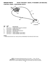
MODEL P14530ES (96198004502) CONTROL PANEL / DISCHARGE CHUTE 2 2 1 *3 *7 *6 KEY NO. 1 2 *3 *4 *5 *6 *7 PART NO. 532 42 82-72 817 54 10-08 532 42 06-78 532 40 59-32 532 42 06-75 532 42 82-73 ... CABLE ASSEMBLY HEAT SHIELD *4 *5 01.09.010-C NOTES: 1. NOTE: All component dimensions given in U.S. inches. 1 inch = 25.4 mm IMPORTANT: Use only Original Equipment Manufacturer (O.E.M.) replacement parts. Failure to do so could be hazardous, damage your snow thrower and void your warranty. 25 ITEMS INDICATED WITH AN * ARE LISTED AS REFERENCE FOR...
MODEL P14530ES (96198004502) CONTROL PANEL / DISCHARGE CHUTE 2 2 1 *3 *7 *6 KEY NO. 1 2 *3 *4 *5 *6 *7 PART NO. 532 42 82-72 817 54 10-08 532 42 06-78 532 40 59-32 532 42 06-75 532 42 82-73 ... CABLE ASSEMBLY HEAT SHIELD *4 *5 01.09.010-C NOTES: 1. NOTE: All component dimensions given in U.S. inches. 1 inch = 25.4 mm IMPORTANT: Use only Original Equipment Manufacturer (O.E.M.) replacement parts. Failure to do so could be hazardous, damage your snow thrower and void your warranty. 25 ITEMS INDICATED WITH AN * ARE LISTED AS REFERENCE FOR...
User Manual
Page 26
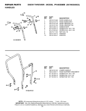
inches. 1 inch = 25.4 mm IMPORTANT: Use only Original Equipment Manufacturer (O.E.M.) replacement parts. NO. REPAIR PARTS HANDLES SNOW THROWER - MODEL P14530ES (96198004502) 5 1 10 KEY PART 6 NO. DESCRIPTION 8 5 8 6 2 39 7 8 49 7 1 532 42 10-69 PLOW HANDLE LH 2 532 42 10-70 PLOW HANDLE RH 3 532 42 91-48 PANEL BRACKET LH 4 ... 11-53 NUT 5/16−18 9 532 15 54-15 WASHER 10 532 05 38-47 WASHER 01.08.003-B 1 4 3 2 4 3 5 5 01.05.013-D KEY NO. 1 2 3 4 5 PART NO. 585 23 81-02 532 44 36-17 817 00 05-10 817 00 06-16 817 00 06-12 DESCRIPTION LOWER HANDLE PIVOT...
inches. 1 inch = 25.4 mm IMPORTANT: Use only Original Equipment Manufacturer (O.E.M.) replacement parts. NO. REPAIR PARTS HANDLES SNOW THROWER - MODEL P14530ES (96198004502) 5 1 10 KEY PART 6 NO. DESCRIPTION 8 5 8 6 2 39 7 8 49 7 1 532 42 10-69 PLOW HANDLE LH 2 532 42 10-70 PLOW HANDLE RH 3 532 42 91-48 PANEL BRACKET LH 4 ... 11-53 NUT 5/16−18 9 532 15 54-15 WASHER 10 532 05 38-47 WASHER 01.08.003-B 1 4 3 2 4 3 5 5 01.05.013-D KEY NO. 1 2 3 4 5 PART NO. 585 23 81-02 532 44 36-17 817 00 05-10 817 00 06-16 817 00 06-12 DESCRIPTION LOWER HANDLE PIVOT...


