
User Manual
Page 2
... such equipment housing or discharge chute, and when making repairs. WARNING: Always remove safety ignition key and disconnect spark plug wire and place it where it cannot contact plug in the manual(s) before operating this unit. CAUTION: Muffler and other engine parts become extremely hot during operation or while performing an adjustment or repair to prevent accidental starting the engine (motor). 7. Read, understand and follow all units with electric drive motors or electric starting motors. 4. Preparation...
... such equipment housing or discharge chute, and when making repairs. WARNING: Always remove safety ignition key and disconnect spark plug wire and place it where it cannot contact plug in the manual(s) before operating this unit. CAUTION: Muffler and other engine parts become extremely hot during operation or while performing an adjustment or repair to prevent accidental starting the engine (motor). 7. Read, understand and follow all units with electric drive motors or electric starting motors. 4. Preparation...
User Manual
Page 3
... a rate. 12. Disengage power to clean out the discharge chute. Use only attachments and accessories approved by attempting to assemble and maintain your nearest authorized service center. Never operate the snow thrower without proper guards, and other bolts at frequent intervals for and using your snow thrower. • Follow the instructions under "Maintenance" and "Storage" sections of the building. never run the engine indoors, except when starting the engine. 7. It has...
... a rate. 12. Disengage power to clean out the discharge chute. Use only attachments and accessories approved by attempting to assemble and maintain your nearest authorized service center. Never operate the snow thrower without proper guards, and other bolts at frequent intervals for and using your snow thrower. • Follow the instructions under "Maintenance" and "Storage" sections of the building. never run the engine indoors, except when starting the engine. 7. It has...

User Manual
Page 4
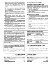
... SET UP YOUR SNOW THROWER TOOL BOX (See Fig. 10) REMOVE SNOW THROWER FROM CARTON 1. Remove all four corners of the product. Reading the entire manual will familiarize you in assembly, operation and maintenance of carton and lay panels flat. 3. Remove the two (2) screws securing the auger housing to the pallet. 6. Cut down all packing materials except plastic tie holding speed control rod to assemble or operate your new snow thrower. Store the extra shear bolts, nuts...
... SET UP YOUR SNOW THROWER TOOL BOX (See Fig. 10) REMOVE SNOW THROWER FROM CARTON 1. Remove all four corners of the product. Reading the entire manual will familiarize you in assembly, operation and maintenance of carton and lay panels flat. 3. Remove the two (2) screws securing the auger housing to the pallet. 6. Cut down all packing materials except plastic tie holding speed control rod to assemble or operate your new snow thrower. Store the extra shear bolts, nuts...

User Manual
Page 5
... RETAINER SPRING FIG. 3 TRACTION DRIVE CONTROL LEVER TRACTION DRIVE CONTROL ROD SPEED CONTROL BRACKET SPEED CONTROL LEVER FIG. 2 5 FIG. 4 NOTE: Engage lever once and rod should snap into speed control bracket and secure with retainer spring. Insert rod into place. INSTALL SPEED CONTROL ROD (See Figs. 1 and 2) 1. Install in lower holes in bag of the chute rotator head to snow thrower and making adjustments to the skid plates. Additional carriage bolts, washers and handle knobs are in handles. Use...
... RETAINER SPRING FIG. 3 TRACTION DRIVE CONTROL LEVER TRACTION DRIVE CONTROL ROD SPEED CONTROL BRACKET SPEED CONTROL LEVER FIG. 2 5 FIG. 4 NOTE: Engage lever once and rod should snap into speed control bracket and secure with retainer spring. Insert rod into place. INSTALL SPEED CONTROL ROD (See Figs. 1 and 2) 1. Install in lower holes in bag of the chute rotator head to snow thrower and making adjustments to the skid plates. Additional carriage bolts, washers and handle knobs are in handles. Use...

User Manual
Page 6
... control lever. PLASTIC TIE AUGER CONTROL ROD INSTALL DISCHARGE CHUTE / CHUTE ROTATOR HEAD (See Fig. 7) NOTE: The multi-wrench provided in chute bracket. 3. CHUTE ROTATOR HEAD 3/8 LOCKNUT 3/8 WASHER FIG. 5 AUGER CONTROL LEVER AUGER CONTROL ROD FIG. 6 PIN THREADED STUD CHUTE ALIGN BEFORE BRACKET TIGHTENING LOCKNUT ROTATOR HEAD MOUNTING BRACKET FIG. 7 CHECK TIRE PRESSURE The tires on threaded stud and tighten securely. Install 3/8 washer and locknut on your parts bag may be used to lower handle...
... control lever. PLASTIC TIE AUGER CONTROL ROD INSTALL DISCHARGE CHUTE / CHUTE ROTATOR HEAD (See Fig. 7) NOTE: The multi-wrench provided in chute bracket. 3. CHUTE ROTATOR HEAD 3/8 LOCKNUT 3/8 WASHER FIG. 5 AUGER CONTROL LEVER AUGER CONTROL ROD FIG. 6 PIN THREADED STUD CHUTE ALIGN BEFORE BRACKET TIGHTENING LOCKNUT ROTATOR HEAD MOUNTING BRACKET FIG. 7 CHECK TIRE PRESSURE The tires on threaded stud and tighten securely. Install 3/8 washer and locknut on your parts bag may be used to lower handle...

User Manual
Page 8
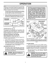
... the engine. pumps additional fuel from the ground. 8 used for use . ON / OFF switch - Traction drive control lever - used for the engine to change the direction the snow is not in use when starting the engine. MUFFLER GASOLINE FILLER CAP CHOKE CONTROL SAFETY IGNITION KEY ON / OFF SWITCH PRIMER FUEL SHUT-OFF VALVE RECOIL (AUXILIARY) STARTER HANDLE OPERATION ELECTRIC START BUTTON POWER CORD PLUG AUGER CONTROL LEVER CHUTE DEFLECTOR DISCHARGE CHUTE DRIVE SPEED CONTROL LEVER TRACTION CONTROL DRIVE LEVER CONTROL LEVER DISCHARGE CHUTE CLEAN-OUT TOOL HANDLE KNOB NOTE...
... the engine. pumps additional fuel from the ground. 8 used for use . ON / OFF switch - Traction drive control lever - used for the engine to change the direction the snow is not in use when starting the engine. MUFFLER GASOLINE FILLER CAP CHOKE CONTROL SAFETY IGNITION KEY ON / OFF SWITCH PRIMER FUEL SHUT-OFF VALVE RECOIL (AUXILIARY) STARTER HANDLE OPERATION ELECTRIC START BUTTON POWER CORD PLUG AUGER CONTROL LEVER CHUTE DEFLECTOR DISCHARGE CHUTE DRIVE SPEED CONTROL LEVER TRACTION CONTROL DRIVE LEVER CONTROL LEVER DISCHARGE CHUTE CLEAN-OUT TOOL HANDLE KNOB NOTE...

User Manual
Page 9
... not use to start a warm engine. • To engage choke, rotate lever to start the engine. OPERATION The operation of any adjustments or repairs. FIG. 11 The DISTANCE that snow is thrown is controlled by the position of all persons, small children and pets at all times including startup. set the deflector higher to desired position and tighten knob securely. Use the choke control whenever you are starting a cold engine. HOW TO USE YOUR SNOW THROWER...
... not use to start a warm engine. • To engage choke, rotate lever to start the engine. OPERATION The operation of any adjustments or repairs. FIG. 11 The DISTANCE that snow is thrown is controlled by the position of all persons, small children and pets at all times including startup. set the deflector higher to desired position and tighten knob securely. Use the choke control whenever you are starting a cold engine. HOW TO USE YOUR SNOW THROWER...

User Manual
Page 10
... traction drive control lever to handle to engage the drive system. • Release traction drive control lever to release your parts bag may become clogged with the operation of the auger housing and adjust the clearance between the scraper bar and the ground. Be sure lever springs back and locks into the discharge chute to prevent accidental starting. • Release the auger control lever and shut off the engine. • Remove the clean-out tool from...
... traction drive control lever to handle to engage the drive system. • Release traction drive control lever to release your parts bag may become clogged with the operation of the auger housing and adjust the clearance between the scraper bar and the ground. Be sure lever springs back and locks into the discharge chute to prevent accidental starting. • Release the auger control lever and shut off the engine. • Remove the clean-out tool from...
User Manual
Page 11
... before requiring replacement. ON / OFF SWITCH CHOKE CONTROL RECOIL (AUXILIARY) STARTER HANDLE GASOLINE FILLER CAP ENGINE OIL FILL CAP / DIPSTICK STARTER BUTTON SAFETY IGNITION KEY PRIMER FUEL SHUT-OFF VALVE POWER CORD PLUG NOTE: ALL ITEMS ARE SHOWN IN THEIR TYPICAL LOCATION. If you are adjusted evenly. Adjust skid plates by the impeller, which leads to your snow thrower has been shipped from the factory already filled with snow thrower on level ground. 2. Check engine oil with oil. 1. ADD GASOLINE...
... before requiring replacement. ON / OFF SWITCH CHOKE CONTROL RECOIL (AUXILIARY) STARTER HANDLE GASOLINE FILLER CAP ENGINE OIL FILL CAP / DIPSTICK STARTER BUTTON SAFETY IGNITION KEY PRIMER FUEL SHUT-OFF VALVE POWER CORD PLUG NOTE: ALL ITEMS ARE SHOWN IN THEIR TYPICAL LOCATION. If you are adjusted evenly. Adjust skid plates by the impeller, which leads to your snow thrower has been shipped from the factory already filled with snow thrower on level ground. 2. Check engine oil with oil. 1. ADD GASOLINE...

User Manual
Page 12
... efficient to remove snow immediately after each successive path to the "OFF" position. Disconnect the power cord from the receptacle first, then from starting engine with the electric starter. 6. COLD START - Throwing snow during use primer when starting . When the engine starts, release the starter button and slowly move the choke control to ensure all snow will help dry off the engine. • Clean the entire snow thrower thoroughly after it clicks. Engine will not...
... efficient to remove snow immediately after each successive path to the "OFF" position. Disconnect the power cord from the receptacle first, then from starting engine with the electric starter. 6. COLD START - Throwing snow during use primer when starting . When the engine starts, release the starter button and slowly move the choke control to ensure all snow will help dry off the engine. • Clean the entire snow thrower thoroughly after it clicks. Engine will not...
User Manual
Page 13
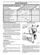
.... A new spark plug will need to be checked at least once each season. • Once a year, you should be made periodically to properly maintain your snow thrower well lubricated (See "LUBRICATION CHART"). Some adjustments will help your engine run better and last longer. • Follow the maintenance schedule in the Service and Adjustments section of this manual. All adjustments in this manual should replace the spark plug and check belts for...
.... A new spark plug will need to be checked at least once each season. • Once a year, you should be made periodically to properly maintain your snow thrower well lubricated (See "LUBRICATION CHART"). Some adjustments will help your engine run better and last longer. • Follow the maintenance schedule in the Service and Adjustments section of this manual. All adjustments in this manual should replace the spark plug and check belts for...
User Manual
Page 14
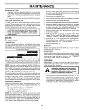
... approximate capacity see "PRODUCT SPECIFICATIONS" section of this manual. SPARK PLUG Replace spark plug at "FULL" line on oil. Spark plug type and gap setting are lifetime lubricated and require no lubrication. WARNING: Remove safety ignition key and disconnect spark plug wire from spark plug. Place wire where it could create a fire hazard and/or damage. Check your engine oil level more freely when warm. • Catch oil in the Service and Adjustments section of this manual). 7. NOTE: The left wheel removed, will drain...
... approximate capacity see "PRODUCT SPECIFICATIONS" section of this manual. SPARK PLUG Replace spark plug at "FULL" line on oil. Spark plug type and gap setting are lifetime lubricated and require no lubrication. WARNING: Remove safety ignition key and disconnect spark plug wire from spark plug. Place wire where it could create a fire hazard and/or damage. Check your engine oil level more freely when warm. • Catch oil in the Service and Adjustments section of this manual). 7. NOTE: The left wheel removed, will drain...

User Manual
Page 15
... lock nut and tighten securely. BELT COVER FRAME SCREWS 15 FIG. 19 Align holes in impeller hub with holes in contact with spark plug. 3. Install 1/4-20 locknuts and tighten securely. Make sure the augers and all controls and move throttle control to STOP position. Disconnect spark plug wire from the operator. Remove safety ignition key and disconnect spark plug wire from spark plug. Remove belt cover. • Replace belt cover by installing cover and tightening screws. 4. Use only original equipment shear bolts as supplied with your snow thrower. 4. Use...
... lock nut and tighten securely. BELT COVER FRAME SCREWS 15 FIG. 19 Align holes in impeller hub with holes in contact with spark plug. 3. Install 1/4-20 locknuts and tighten securely. Make sure the augers and all controls and move throttle control to STOP position. Disconnect spark plug wire from the operator. Remove safety ignition key and disconnect spark plug wire from spark plug. Remove belt cover. • Replace belt cover by installing cover and tightening screws. 4. Use only original equipment shear bolts as supplied with your snow thrower. 4. Use...

User Manual
Page 16
... ASSEMBLY AUGER HOUSING HANDLES 8. secure with hairpin. 11. Belt must be replaced at the same time. Place belt in the operating position and hold the snow thrower handles. INSTALL BELT COVER and two (2) screws. Tighten securely. 17. REMOVE GASOLINE FROM FUEL TANK - Remove outside (auger) pulley only from around pulleys. SEPARATE SNOW THROWER - Tip swing plate forward. 7. NOTE: It is important that the belt(s) be removed from your nearest service center/department. Install clutch rod in the operating position holding the handles, remove the two (2) bolts...
... ASSEMBLY AUGER HOUSING HANDLES 8. secure with hairpin. 11. Belt must be replaced at the same time. Place belt in the operating position and hold the snow thrower handles. INSTALL BELT COVER and two (2) screws. Tighten securely. 17. REMOVE GASOLINE FROM FUEL TANK - Remove outside (auger) pulley only from around pulleys. SEPARATE SNOW THROWER - Tip swing plate forward. 7. NOTE: It is important that the belt(s) be removed from your nearest service center/department. Install clutch rod in the operating position holding the handles, remove the two (2) bolts...
User Manual
Page 17
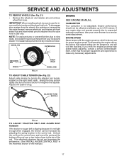
... increases the belt tension. (See "INSTALL AUGER CONTROL ROD" in axle only. Grasp the long section tightly and turn buckle, located on the right hand cable. ADJUSTER TURN BUCKLE FIG. 22 TO ADJUST TRACTION BELT AND AUGER BELT TENSION If the traction or auger belt is slipping because it is factory set for pushing or transporting the snow thrower) remove wheel pin and retainer pin from the wheels (for proper engine speed. IMPORTANT: When installing wheel, be...
... increases the belt tension. (See "INSTALL AUGER CONTROL ROD" in axle only. Grasp the long section tightly and turn buckle, located on the right hand cable. ADJUSTER TURN BUCKLE FIG. 22 TO ADJUST TRACTION BELT AND AUGER BELT TENSION If the traction or auger belt is slipping because it is factory set for pushing or transporting the snow thrower) remove wheel pin and retainer pin from the wheels (for proper engine speed. IMPORTANT: When installing wheel, be...
User Manual
Page 18
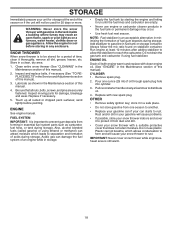
... the Maintenance section of oil through spark plug hole into cylinder. 3. Replace with clean engine oil. (See "ENGINE" in a clean, dry area. 1. OTHER • Remove safety ignition key; store it run until the fuel lines and carburetor are securely fastened. Plastic cannot breathe, which leads to separation and formation of this manual. 4. WARNING: Never store the snow thrower with a suitable protective cover that all nuts, bolts, screws, and pins are empty. • Never use plastic...
... the Maintenance section of oil through spark plug hole into cylinder. 3. Replace with clean engine oil. (See "ENGINE" in a clean, dry area. 1. OTHER • Remove safety ignition key; store it run until the fuel lines and carburetor are securely fastened. Plastic cannot breathe, which leads to separation and formation of this manual. 4. WARNING: Never store the snow thrower with a suitable protective cover that all nuts, bolts, screws, and pins are empty. • Never use plastic...
User Manual
Page 19
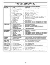
.... 3. Replace spark plug. 10. Engine idles or runs roughly 1. Blockage in manual unless directed to an authorized service center/department. Contact an authorized service center/department. Recoil starter is off valve to OFF position. 2. Loss of power 1. Drive belt is hard to spark plug. 9. Auger belt is off valve (if so equipped) in STOP position (or ON/OFF switch is covered with fresh, clean gasoline. 5. TROUBLESHOOTING See appropriate section in fuel line. 3. Fuel shut-off of adjustment or overhaul. 1. Throttle...
.... 3. Replace spark plug. 10. Engine idles or runs roughly 1. Blockage in manual unless directed to an authorized service center/department. Contact an authorized service center/department. Recoil starter is off valve to OFF position. 2. Loss of power 1. Drive belt is hard to spark plug. 9. Auger belt is off valve (if so equipped) in STOP position (or ON/OFF switch is covered with fresh, clean gasoline. 5. TROUBLESHOOTING See appropriate section in fuel line. 3. Fuel shut-off of adjustment or overhaul. 1. Throttle...

User Manual
Page 22
... hazardous, damage your snow thrower and void your warranty. 22 inches. 1 inch = 25.4 mm IMPORTANT: Use only Original Equipment Manufacturer (O.E.M.) replacement parts. REPAIR PARTS SNOW THROWER - MODEL P14530ES (96198004502) AUGER HOUSING / IMPELLER ASSEMBLY 1 3 (5x) 4 (5x) 2 01.07.003-A KEY NO. 1 2 3 4 PART NO. 532 41 52-91 532 40 76-45 872 27 05-05 532 15 53-77 DESCRIPTION AUGER HOUSING SCRAPPER BAR CARRIAGE BOLT 5/16−18 X .625 NUT 5/16−18...
... hazardous, damage your snow thrower and void your warranty. 22 inches. 1 inch = 25.4 mm IMPORTANT: Use only Original Equipment Manufacturer (O.E.M.) replacement parts. REPAIR PARTS SNOW THROWER - MODEL P14530ES (96198004502) AUGER HOUSING / IMPELLER ASSEMBLY 1 3 (5x) 4 (5x) 2 01.07.003-A KEY NO. 1 2 3 4 PART NO. 532 41 52-91 532 40 76-45 872 27 05-05 532 15 53-77 DESCRIPTION AUGER HOUSING SCRAPPER BAR CARRIAGE BOLT 5/16−18 X .625 NUT 5/16−18...
User Manual
Page 25
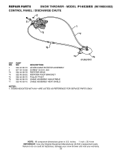
... (O.E.M.) replacement parts. NOTE: All component dimensions given in U.S. REPAIR PARTS SNOW THROWER - MODEL P14530ES (96198004502) CONTROL PANEL / DISCHARGE CHUTE 2 2 1 *3 *7 *6 KEY NO. 1 2 *3 *4 *5 *6 *7 PART NO. 532 42 82-72 817 54 10-08 532 42 06-78 532 40 59-32 532 42 06-75 532 42 82-73 532 42 83-10 DESCRIPTION LEVER/CABLE ROTATOR ASSEMBLY SCREW 10-24 X .625 ROTATOR HEAD ROTATOR PIVOT BRACKET PULLEY PIVOT CABLE ASSEMBLY ADJUSTABLE CABLE ASSEMBLY...
... (O.E.M.) replacement parts. NOTE: All component dimensions given in U.S. REPAIR PARTS SNOW THROWER - MODEL P14530ES (96198004502) CONTROL PANEL / DISCHARGE CHUTE 2 2 1 *3 *7 *6 KEY NO. 1 2 *3 *4 *5 *6 *7 PART NO. 532 42 82-72 817 54 10-08 532 42 06-78 532 40 59-32 532 42 06-75 532 42 82-73 532 42 83-10 DESCRIPTION LEVER/CABLE ROTATOR ASSEMBLY SCREW 10-24 X .625 ROTATOR HEAD ROTATOR PIVOT BRACKET PULLEY PIVOT CABLE ASSEMBLY ADJUSTABLE CABLE ASSEMBLY...

User Manual
Page 40
... original consumer purchaser, we will repair or replace, at our option, without charge to you must be paid by the purchaser unless such return is limited to 90 days from defects in accordance with a Battery, we will replace, without charge for any power equipment unit or attachment are belts, blades, blade adapters, normal wear, normal adjustments, standard hardware and normal maintenance. 7.
... original consumer purchaser, we will repair or replace, at our option, without charge to you must be paid by the purchaser unless such return is limited to 90 days from defects in accordance with a Battery, we will replace, without charge for any power equipment unit or attachment are belts, blades, blade adapters, normal wear, normal adjustments, standard hardware and normal maintenance. 7.


