

User Manual
Page 2
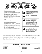
..., not across. • Remove obstacles such as required. 2 Repair, if necessary, before turning. • Never leave a running . CHILDREN Tragic accidents can result in handling gasoline and other objects that operators, age 60 years and above, are familiar with grass catchers or other attachments. Children are explosive. - Never remove gas cap or add fuel with manufacturer's recommended parts, when necessary. • Mower blades are subject to cool...
..., not across. • Remove obstacles such as required. 2 Repair, if necessary, before turning. • Never leave a running . CHILDREN Tragic accidents can result in handling gasoline and other objects that operators, age 60 years and above, are familiar with grass catchers or other attachments. Children are explosive. - Never remove gas cap or add fuel with manufacturer's recommended parts, when necessary. • Mower blades are subject to cool...
User Manual
Page 3
...; Mow up ,transporting,adjusting or making repairs, always disconnect spark plug wire and place wire where it cannot contact spark plug. Too heavy of Manual 3 Please read and retain this manual.The instructions will not have competent, well trained technicians and the proper tools to service or repair this symbol to stop or shift while on slopes unless necessary, and then, turn machine off . •...
...; Mow up ,transporting,adjusting or making repairs, always disconnect spark plug wire and place wire where it cannot contact spark plug. Too heavy of Manual 3 Please read and retain this manual.The instructions will not have competent, well trained technicians and the proper tools to service or repair this symbol to stop or shift while on slopes unless necessary, and then, turn machine off . •...
User Manual
Page 4
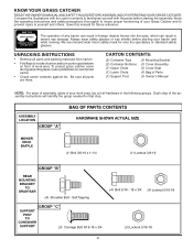
KNOW YOUR GRASS CATCHER READTHIS OWNER'S MANUAL AND SAFETY RULES BEFORE ASSEMBLING OR OPERATINGYOUR GRASS CATCHER. ASSEMBLY LOCATION GROUP "A" BAG OF PARTS CONTENTS HARDWARE SHOWN ACTUAL SIZE MOWER DECK BAFFLE (1) Bolt 3/8-16 x 1-1/4 (1) Locknut 3/8-16 GROUP "B" REAR MOUNTING BRACKET TO DRAW BAR (4) Shoulder Bolt - We recommend wide vision safety mask for over the spectacles or standard safety glasses. 00155 UNPACKING INSTRUCTIONS • Remove all parts and packing materials from carton. •...
KNOW YOUR GRASS CATCHER READTHIS OWNER'S MANUAL AND SAFETY RULES BEFORE ASSEMBLING OR OPERATINGYOUR GRASS CATCHER. ASSEMBLY LOCATION GROUP "A" BAG OF PARTS CONTENTS HARDWARE SHOWN ACTUAL SIZE MOWER DECK BAFFLE (1) Bolt 3/8-16 x 1-1/4 (1) Locknut 3/8-16 GROUP "B" REAR MOUNTING BRACKET TO DRAW BAR (4) Shoulder Bolt - We recommend wide vision safety mask for over the spectacles or standard safety glasses. 00155 UNPACKING INSTRUCTIONS • Remove all parts and packing materials from carton. •...
User Manual
Page 5
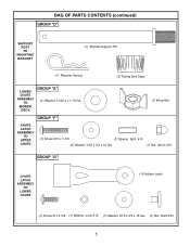
BAG OF PARTS CONTENTS (continued) GROUP "D" SUPPORT POST TO MOUNTING BRACKET (1) Bracket Support Pin (1) Retainer Spring (3) Tubing End Caps LOWER CHUTE ASSEMBLY TO MOWER DECK GROUP "E" (1) Washer 13/32 x 1 x 16 Ga. (1) Wing Nut GROUP "F" CHUTE LATCH ASSEMBLY TO UPPER CHUTE (1) Screw #10 x 1-1/8 (1) Spacer, Split #10 (2) Washer 3/16 x 3/4 x 16 Ga. (1) Nut, Acorn #10 GROUP "G" CHUTE LATCH ASSEMBLY TO LOWER CHUTE (1) Rubber Latch (1) Screw #10 x 5/8 (1) Washer, Lock #10 (1) Washer 3/16 x 3/4 x 16 Ga. (1) Nut, Weld #10 5
BAG OF PARTS CONTENTS (continued) GROUP "D" SUPPORT POST TO MOUNTING BRACKET (1) Bracket Support Pin (1) Retainer Spring (3) Tubing End Caps LOWER CHUTE ASSEMBLY TO MOWER DECK GROUP "E" (1) Washer 13/32 x 1 x 16 Ga. (1) Wing Nut GROUP "F" CHUTE LATCH ASSEMBLY TO UPPER CHUTE (1) Screw #10 x 1-1/8 (1) Spacer, Split #10 (2) Washer 3/16 x 3/4 x 16 Ga. (1) Nut, Acorn #10 GROUP "G" CHUTE LATCH ASSEMBLY TO LOWER CHUTE (1) Rubber Latch (1) Screw #10 x 5/8 (1) Washer, Lock #10 (1) Washer 3/16 x 3/4 x 16 Ga. (1) Nut, Weld #10 5

User Manual
Page 6
... THE TOOLS YOU WILL NEED TO ASSEMBLE YOUR GRASS CATCHER: (1) 3/8" Wrench (1) Drive Ratchet (1) 1/2" Wrench (1) 3" or longer Extension (2) 9/16" Wrenches (1) Short Handle (1) 1/2" Socket Phillips Screwdriver (1) 9/16" Deep well Socket CAUTION: BEFORE ASSEMBLING GRASS CATCHER TO TRACTOR: • Depress clutch/brake pedal fully and set parking brake. • Place gearshift/motion control lever in neutral (N) position. • Place attachment clutch in "DISENGAGED" position. • Turn ignition key "OFF" and remove key. • Make sure the blade and...
... THE TOOLS YOU WILL NEED TO ASSEMBLE YOUR GRASS CATCHER: (1) 3/8" Wrench (1) Drive Ratchet (1) 1/2" Wrench (1) 3" or longer Extension (2) 9/16" Wrenches (1) Short Handle (1) 1/2" Socket Phillips Screwdriver (1) 9/16" Deep well Socket CAUTION: BEFORE ASSEMBLING GRASS CATCHER TO TRACTOR: • Depress clutch/brake pedal fully and set parking brake. • Place gearshift/motion control lever in neutral (N) position. • Place attachment clutch in "DISENGAGED" position. • Turn ignition key "OFF" and remove key. • Make sure the blade and...
User Manual
Page 7
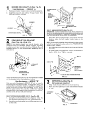
Raise your tractor mower deck to tractor at cover opening so cover sits between flanges of (4) four bolts and locknuts. Discard hardware group "B" and disregard the remaining Step 2 instructions. Assemble the mounting bracket, lanced tabs towards bottom, using the four smaller inside holes on seal with mark at this manual. 2. If drawbar was removed from tractor, reassemble to its highest position. 2. Align mark on...
Raise your tractor mower deck to tractor at cover opening so cover sits between flanges of (4) four bolts and locknuts. Discard hardware group "B" and disregard the remaining Step 2 instructions. Assemble the mounting bracket, lanced tabs towards bottom, using the four smaller inside holes on seal with mark at this manual. 2. If drawbar was removed from tractor, reassemble to its highest position. 2. Align mark on...
User Manual
Page 8
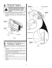
... cover closed, lift assembly and place support post inside mounting bracket. Rotate cover assembly onto its side as not to be mounted. 2. Tighten securely. BRACKET SUPPORT PIN CARRIAGE BOLTS COVER ASSEMBLY RETAINER SPRING 02096 SUPPORT POST 02091 LOCKNUTS END CAP SUPPORT POST FIG. 4 LANCED TABS 5 MOUNTING TO TRACTOR (See Fig. 5) Use Hardware - - Assemble support post to tractor. 1. Allow assembly to rest on tractor to allow assembly to unlatch the cover from the container support. 1. Handle cover assembly...
... cover closed, lift assembly and place support post inside mounting bracket. Rotate cover assembly onto its side as not to be mounted. 2. Tighten securely. BRACKET SUPPORT PIN CARRIAGE BOLTS COVER ASSEMBLY RETAINER SPRING 02096 SUPPORT POST 02091 LOCKNUTS END CAP SUPPORT POST FIG. 4 LANCED TABS 5 MOUNTING TO TRACTOR (See Fig. 5) Use Hardware - - Assemble support post to tractor. 1. Allow assembly to rest on tractor to allow assembly to unlatch the cover from the container support. 1. Handle cover assembly...
User Manual
Page 9
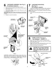
Install other container to separate container halves and repeat instructions above. If a gap appears, unlock tabs to right side. GROUP "E" 1. Align slot in mower deck baffle and close chute over deck openning. 4. Secure with hex bolt in lower chute with washer and wing nut. WASHER DEFLECTOR SHIELD MOWER DECK BAFFLE 02097 W DrenlndyoitesAlnyds.ouRrRteboepjNepplacelIatcrNcaetoetmGewwemenhaoterwcnoacennrratduacnkidneleeedtsrie.sorricodoraanmttiaoainng.eeCrdih.seUpcsrkoebpoaenglyfraeqreucomme 02343 WING NUT HEX BOLT 9 FIG. 8 6 CONTAINER ASSEMBLY (See...
Install other container to separate container halves and repeat instructions above. If a gap appears, unlock tabs to right side. GROUP "E" 1. Align slot in mower deck baffle and close chute over deck openning. 4. Secure with hex bolt in lower chute with washer and wing nut. WASHER DEFLECTOR SHIELD MOWER DECK BAFFLE 02097 W DrenlndyoitesAlnyds.ouRrRteboepjNepplacelIatcrNcaetoetmGewwemenhaoterwcnoacennrratduacnkidneleeedtsrie.sorricodoraanmttiaoainng.eeCrdih.seUpcsrkoebpoaenglyfraeqreucomme 02343 WING NUT HEX BOLT 9 FIG. 8 6 CONTAINER ASSEMBLY (See...
User Manual
Page 10
NOTE: Handle carefully so as shown. 2. Push in and turn upper chute until it is properly leveled for instructions. 10 See your tractors owner's manual for best mower performance. Align the bosses on upper chute and slide together. 5. COVER UPPER CHUTE DUMP BAG INDICATOR HANDLE 02344 WARNING csDruaobcjnkeoectdtotooprewdreaaatmeramagnoedwdd.eeUr tusieenrlieoosnraslytcioaonnr.etCaciohnmeecrmkisebnpadrgoepfdreerrqelyupieslannctelsytm.aRleleendpt .lcCaoconentatwainhineeern.r is WARNING csDruaobcjnkeoectdtotooprewdreaaatmeramagnoedwdd.eeUr tusieenrlieoosnraslytcioaonnr....
NOTE: Handle carefully so as shown. 2. Push in and turn upper chute until it is properly leveled for instructions. 10 See your tractors owner's manual for best mower performance. Align the bosses on upper chute and slide together. 5. COVER UPPER CHUTE DUMP BAG INDICATOR HANDLE 02344 WARNING csDruaobcjnkeoectdtotooprewdreaaatmeramagnoedwdd.eeUr tusieenrlieoosnraslytcioaonnr.etCaciohnmeecrmkisebnpadrgoepfdreerrqelyupieslannctelsytm.aRleleendpt .lcCaoconentatwainhineeern.r is WARNING csDruaobcjnkeoectdtotooprewdreaaatmeramagnoedwdd.eeUr tusieenrlieoosnraslytcioaonnr....

User Manual
Page 11
.... When operating your grass catcher on a lawn where grass and leaf bagging equipment has not been used, you will drop down in chutes. - The first time relatively high, the second time to damage the parts and that has accumulated for ease of the plastic lawn bag. Disengage blades, shift into passageway to empty containers, unclogging chutes, etc. • Close cover before starting. • Disengage mower when crossing...
.... When operating your grass catcher on a lawn where grass and leaf bagging equipment has not been used, you will drop down in chutes. - The first time relatively high, the second time to damage the parts and that has accumulated for ease of the plastic lawn bag. Disengage blades, shift into passageway to empty containers, unclogging chutes, etc. • Close cover before starting. • Disengage mower when crossing...

User Manual
Page 12
... "DISENGAGED" position. • Turn ignition key to "OFF" position. • Make sure blades and all dirt, grass, leaves, etc. CAUTION: BEFORE PERFORMING ANY MAINTENANCE,SERVICE OR ADJUSTMENTS: • Depress clutch brake pedal fully and set parking brake. • Place gearshift/motion control lever in "NEUTRAL" position. • Place clutch control in contact with manufacturer's recommended parts, when necessary. 12 Empty containers after each use . Frequently check components and replace with plug. CAUTION: Grass catcher components...
... "DISENGAGED" position. • Turn ignition key to "OFF" position. • Make sure blades and all dirt, grass, leaves, etc. CAUTION: BEFORE PERFORMING ANY MAINTENANCE,SERVICE OR ADJUSTMENTS: • Depress clutch brake pedal fully and set parking brake. • Place gearshift/motion control lever in "NEUTRAL" position. • Place clutch control in contact with manufacturer's recommended parts, when necessary. 12 Empty containers after each use . Frequently check components and replace with plug. CAUTION: Grass catcher components...

User Manual
Page 13
... spark plug wire from spark plug and place wire where it may need: (1) Heavy Shears or (1) Hand Saw (1) Ruler (1) Drill Motor (1) 9/32" Drill Bit (1) 11/32" Drill Bit (1) 13/32" Drill Bit (2) 7/16" Wrench (2) 1/2" Wrench (1) 9/16" Wrench A socket wrench set parking brake. • Place gearshift/motion control lever in neutral (N) position. • Place attachment clutch in "DISENGAGED" position. • Turn ignition key "OFF" and remove key. • Make sure the blade and...
... spark plug wire from spark plug and place wire where it may need: (1) Heavy Shears or (1) Hand Saw (1) Ruler (1) Drill Motor (1) 9/32" Drill Bit (1) 11/32" Drill Bit (1) 13/32" Drill Bit (2) 7/16" Wrench (2) 1/2" Wrench (1) 9/16" Wrench A socket wrench set parking brake. • Place gearshift/motion control lever in neutral (N) position. • Place attachment clutch in "DISENGAGED" position. • Turn ignition key "OFF" and remove key. • Make sure the blade and...

User Manual
Page 14
..., using hardware previously removed. Assemble mounting bracket to tractor using a 11/32" drill bit. 7. Keep hardware for the mounting bracket. Using bracket as shown. FIG. 14 02349 DRAWBAR MOUNTING BOLTS (both sides) PROCEED WITH ASSEMBLY INSTRUCTIONS IN THE FRONT OF THIS MANUAL 14 Remove the drawbar by removing the two mounting bolts on all of assembly mounting bracket should line up with a wire loop, drill new mounting...
..., using hardware previously removed. Assemble mounting bracket to tractor using a 11/32" drill bit. 7. Keep hardware for the mounting bracket. Using bracket as shown. FIG. 14 02349 DRAWBAR MOUNTING BOLTS (both sides) PROCEED WITH ASSEMBLY INSTRUCTIONS IN THE FRONT OF THIS MANUAL 14 Remove the drawbar by removing the two mounting bolts on all of assembly mounting bracket should line up with a wire loop, drill new mounting...
User Manual
Page 15
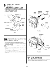
TRIM DEFLECTOR ALONG DOTTED LINE USING EITHER HEAVY SHEARS OR A HAND SAW. MOWER DECK BAFFLE DRILL TEMPLATE TOP EDGE 2" R I G H T E D G E 1-1/4" USE TEMPLATE ABOVE FOR A GUIDE TO DRILLING YOUR MOWER DECK BAFFLE. CUT OUT SHADED AREA AND PLACE ON INSIDE BOTTOM EDGE OF DEFLECTOR. CUT OUT SHADED AREA AND ALIGN WITH TOP, AND RIGHT, EDGE OF BAFFLE. DRILL A 13/32" HOLE AT SPECIFIED LOCATION. 15 DEFLECTOR TRIM TEMPLATE BOTTOM EDGE CUT ALONG DOTTED LINE INSIDE EDGE USE TRIANGLE ABOVE FOR A GUIDE TO TRIMMING YOUR DEFLECTOR SHIELD.
TRIM DEFLECTOR ALONG DOTTED LINE USING EITHER HEAVY SHEARS OR A HAND SAW. MOWER DECK BAFFLE DRILL TEMPLATE TOP EDGE 2" R I G H T E D G E 1-1/4" USE TEMPLATE ABOVE FOR A GUIDE TO DRILLING YOUR MOWER DECK BAFFLE. CUT OUT SHADED AREA AND PLACE ON INSIDE BOTTOM EDGE OF DEFLECTOR. CUT OUT SHADED AREA AND ALIGN WITH TOP, AND RIGHT, EDGE OF BAFFLE. DRILL A 13/32" HOLE AT SPECIFIED LOCATION. 15 DEFLECTOR TRIM TEMPLATE BOTTOM EDGE CUT ALONG DOTTED LINE INSIDE EDGE USE TRIANGLE ABOVE FOR A GUIDE TO TRIMMING YOUR DEFLECTOR SHIELD.

User Manual
Page 17
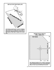
USE 11/32" DRILL BIT USE 9/32" DRILL BIT WIRE LOOP HOLE NEW WIRE LOOP HOLE OLD 17 USE THIS SLOT TO AID IN POSITIONING TEMPLATE HOLE #1 1.) CUT OUT TEMPLATE. 2.) ALIGN TOP AND RIGHT EDGE OF TEMPLATE AND DRAWBAR. 3.) TAPE IN POSITION. 4.) MARK AND DRILL HOLE #1 5.) ASSEMBLE MOUNTING BRACKET TO DRAWBAR, USE BRACKET AS TEMPLATE FOR REMAINING HOLES.
USE 11/32" DRILL BIT USE 9/32" DRILL BIT WIRE LOOP HOLE NEW WIRE LOOP HOLE OLD 17 USE THIS SLOT TO AID IN POSITIONING TEMPLATE HOLE #1 1.) CUT OUT TEMPLATE. 2.) ALIGN TOP AND RIGHT EDGE OF TEMPLATE AND DRAWBAR. 3.) TAPE IN POSITION. 4.) MARK AND DRILL HOLE #1 5.) ASSEMBLE MOUNTING BRACKET TO DRAWBAR, USE BRACKET AS TEMPLATE FOR REMAINING HOLES.


