
User Manual
Page 4
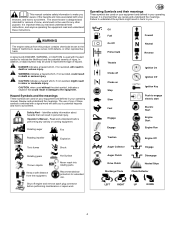
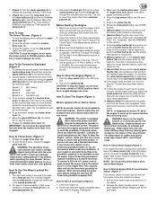
... Electric Start Engine Start Engine Run Rotating impeller Explosion Traction Engine Off Toxic fumes Shock Rotating gears Thrown objects Hot Surface Never reach into rotating parts. It is important that could result in minor or moderate injury. Review and understand the meanings. Recommended ear protection for any activity or running equipment...
... Electric Start Engine Start Engine Run Rotating impeller Explosion Traction Engine Off Toxic fumes Shock Rotating gears Thrown objects Hot Surface Never reach into rotating parts. It is important that could result in minor or moderate injury. Review and understand the meanings. Recommended ear protection for any activity or running equipment...
User Manual
Page 5
...tank indoors. Never fill containers inside a vehicle or on slippery surfaces. unit. Do not operate the unit while under rotating parts. Let engine (motor) and snowthrower adjust to outdoor temperatures enough to obey these safety rules and follow all times. 2. Make... a running unit unattended. Disengage all persons, particularly small children and pets. 4. Avoid loose fitting clothing that could result in moving parts. 4. Never operate the snowthrower without proper instruction. 3. Never leave a running engine or hot engine. 12. Never add fuel to...
...tank indoors. Never fill containers inside a vehicle or on slippery surfaces. unit. Do not operate the unit while under rotating parts. Let engine (motor) and snowthrower adjust to outdoor temperatures enough to obey these safety rules and follow all times. 2. Make... a running unit unattended. Disengage all persons, particularly small children and pets. 4. Avoid loose fitting clothing that could result in moving parts. 4. Never operate the snowthrower without proper instruction. 3. Never leave a running engine or hot engine. 12. Never add fuel to...
User Manual
Page 6
... Period and Air Index information on the engine emissions label. Components are not functioning properly. 13. Use only factory authorized replacement parts when making repairs. 16. If available, look for storage preparations before storing in any source of ignition until fuel vapors have been... activity. Never assume that may obscure vision. Children are present such as necessary. 11. Frequent- Always comply with manufacturer's recommended parts, when necessary. 14. Never use a clean out tool, not your hand to start -up of another responsible adult. 2. SHUT OFF THE...
... Period and Air Index information on the engine emissions label. Components are not functioning properly. 13. Use only factory authorized replacement parts when making repairs. 16. If available, look for storage preparations before storing in any source of ignition until fuel vapors have been... activity. Never assume that may obscure vision. Children are present such as necessary. 11. Frequent- Always comply with manufacturer's recommended parts, when necessary. 14. Never use a clean out tool, not your hand to start -up of another responsible adult. 2. SHUT OFF THE...
User Manual
Page 7
...Figure 7) Fasten chute deflector (2) to flange (4) with the location of fuel and oil to use a safety fuel container. NOTE: Make sure all parts that secure the drift cutters (1) to the pallet. Tighten the fasteners (2). Always use . See the engine manufacturer's instructions for the type of ... snow thrower. WARNING: Always stop the engine. Do not discard any assembly or maintenance to the desired height. 3. NOTE: Fasteners and loose parts are packed separately and remove from the lower holes of the lower handle. 3. (Figure 1) Put the shift lever (6) into the engine....
...Figure 7) Fasten chute deflector (2) to flange (4) with the location of fuel and oil to use a safety fuel container. NOTE: Make sure all parts that secure the drift cutters (1) to the pallet. Tighten the fasteners (2). Always use . See the engine manufacturer's instructions for the type of ... snow thrower. WARNING: Always stop the engine. Do not discard any assembly or maintenance to the desired height. 3. NOTE: Fasteners and loose parts are packed separately and remove from the lower holes of the lower handle. 3. (Figure 1) Put the shift lever (6) into the engine....
User Manual
Page 8
... with the snow thrower. ly adjusted. The power cord must be added to recoil start the engine, have a three--hole grounded receptacle installed by moving parts located on the engine first. Fill the fuel tank with a klick pin (1). See "How To Prepare The Engine". 8 GB 3. Push the stop switch (13) to...
... with the snow thrower. ly adjusted. The power cord must be added to recoil start the engine, have a three--hole grounded receptacle installed by moving parts located on the engine first. Fill the fuel tank with a klick pin (1). See "How To Prepare The Engine". 8 GB 3. Push the stop switch (13) to...
User Manual
Page 9
... running, wipe all salt or other chemicals. Snow Throwing Tips 1. Rocks and gravel must not be made periodically to idle for any loose or damaged parts. See "How To Adjust The Height Of The Skids" in deep, freezing or wet snow. Remove ice, snow and debris from 9 After Each Use G Check...
... running, wipe all salt or other chemicals. Snow Throwing Tips 1. Rocks and gravel must not be made periodically to idle for any loose or damaged parts. See "How To Adjust The Height Of The Skids" in deep, freezing or wet snow. Remove ice, snow and debris from 9 After Each Use G Check...
User Manual
Page 10
... of the scraper bar (15) next to the adjustable skids (7). 4. Items Not To Lubricate (Figure 15) 1. If grease or oil comes in the parts bag) under each season. These skids elevate the front of the tire. 3. For normal hard surfaces, such as a paved driveway or walk, adjust the... the cable. If for correct adjustment, disconnect the "Z" fitting (1) from the traction drive lever (2). 5. (Figure 28) Slide the cable boot (3) off any parts are equally inflated. Do not exceed the maximum amount of air pressure shown on the front end of the scraper bar (15). How To Check...
... of the scraper bar (15) next to the adjustable skids (7). 4. Items Not To Lubricate (Figure 15) 1. If grease or oil comes in the parts bag) under each season. These skids elevate the front of the tire. 3. For normal hard surfaces, such as a paved driveway or walk, adjust the... the cable. If for correct adjustment, disconnect the "Z" fitting (1) from the traction drive lever (2). 5. (Figure 28) Slide the cable boot (3) off any parts are equally inflated. Do not exceed the maximum amount of air pressure shown on the front end of the scraper bar (15). How To Check...
User Manual
Page 12
...the auger housing. The friction wheel must supply the model number (see the individual engine or transmission warranties to obtain proper replacement parts you include this unit. Tighten the bolts (3) on the speed control rod (8). 5. (Figure 23) Install the bottom panel ...thrower with some models) for the engine, transaxle, or transmission, are securely fastened. Lubricate all controls. 2. To obtain replacement parts, contact: BRIGGS AND STRATTON CANADA Factory Customer Service 1195 Coutneypark Drive East Mississauga, Ont. side of the friction wheel (4) to...
...the auger housing. The friction wheel must supply the model number (see the individual engine or transmission warranties to obtain proper replacement parts you include this unit. Tighten the bolts (3) on the speed control rod (8). 5. (Figure 23) Install the bottom panel ...thrower with some models) for the engine, transaxle, or transmission, are securely fastened. Lubricate all controls. 2. To obtain replacement parts, contact: BRIGGS AND STRATTON CANADA Factory Customer Service 1195 Coutneypark Drive East Mississauga, Ont. side of the friction wheel (4) to...
User Manual
Page 13
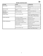
... stale gasoline Unit running on CHOKE. Auger drive belt loose or damaged. Foreign object lodged in fuel system. check fuel supply; Replace drive belt. Loose parts: damaged impeller Drive belt loose or damaged. Clean fuel line; Adjust traction drive cable. Replace friction wheel. Stop engine immediately and disconnect spark plug wire...
... stale gasoline Unit running on CHOKE. Auger drive belt loose or damaged. Foreign object lodged in fuel system. check fuel supply; Replace drive belt. Loose parts: damaged impeller Drive belt loose or damaged. Clean fuel line; Adjust traction drive cable. Replace friction wheel. Stop engine immediately and disconnect spark plug wire...
User Manual
Page 14
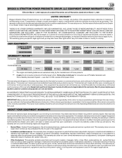
...the unit is performed per the exact instuctions as outlined in place of the owner to this warranty. Transportation charges on parts submitted for prime power in the Operating & Maintenance Instruction. IMPLIED WARRANTIES, INCLUDING THOSE OF MERCHANTABILITY AND FITNESS FOR A PARTICULAR..., LLC will not cover the following repairs and equipment: S Normal Wear: Outdoor Power Equipment, like all mechanical devices, needs periodic parts and service to chemical, dirt, carbon, lime, etc.). S Other Exclusions: This warranty excludes wear items such as adjustments, fuel system...
...the unit is performed per the exact instuctions as outlined in place of the owner to this warranty. Transportation charges on parts submitted for prime power in the Operating & Maintenance Instruction. IMPLIED WARRANTIES, INCLUDING THOSE OF MERCHANTABILITY AND FITNESS FOR A PARTICULAR..., LLC will not cover the following repairs and equipment: S Normal Wear: Outdoor Power Equipment, like all mechanical devices, needs periodic parts and service to chemical, dirt, carbon, lime, etc.). S Other Exclusions: This warranty excludes wear items such as adjustments, fuel system...
User Manual
Page 38
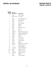
MODEL 96194000200 Key No. No sur le Part No. schéma No de pièce Description 1 198563 CORD, STARTER 2 LH1955P--67510 TEC ENGINE D 3 198539 BOLT, CARRIAGE 5/16--18 4 198540 RETAINER, PUSH 5 ... MOUNT 25--2 198574 SCREW 1/4--20 X .63 25--3 198584 SCREW 5/16--18 X .50 25--4 198766X428 FRAME, MOTOR BOX 27 59289 WASHER -- -- 406885 OWNER'S MANUAL 38 REPAIR PARTS ENGINE / MOTEUR
MODEL 96194000200 Key No. No sur le Part No. schéma No de pièce Description 1 198563 CORD, STARTER 2 LH1955P--67510 TEC ENGINE D 3 198539 BOLT, CARRIAGE 5/16--18 4 198540 RETAINER, PUSH 5 ... MOUNT 25--2 198574 SCREW 1/4--20 X .63 25--3 198584 SCREW 5/16--18 X .50 25--4 198766X428 FRAME, MOTOR BOX 27 59289 WASHER -- -- 406885 OWNER'S MANUAL 38 REPAIR PARTS ENGINE / MOTEUR
User Manual
Page 39
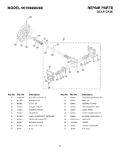
MODEL 96194000200 REPAIR PARTS GEAR CASE Key No. Part No. 41 404965 42 404959 43 404960 44 404952 45 404962 46 404946 47 404964 48 405027X479 49 74780426 50 404950 51 7B36M Description HOUSING, ...GEARCASE, RH SEAL, OIL BEARING, FLANGE KEY, WOODRUFF #605 GEAR, WORM SHAFT, AUGER OUTPUT HOUSING, GEARCASE, LH IMPELLER SCREW GASKET, GEARCASE PIN, ROLL 39 Part No. 19 73800400 27 404953 32 404955 33 404956 34 174684 35 404957 36 404948 37 404944 38 404961 39 404954 40 B6447 Description NUT...
MODEL 96194000200 REPAIR PARTS GEAR CASE Key No. Part No. 41 404965 42 404959 43 404960 44 404952 45 404962 46 404946 47 404964 48 405027X479 49 74780426 50 404950 51 7B36M Description HOUSING, ...GEARCASE, RH SEAL, OIL BEARING, FLANGE KEY, WOODRUFF #605 GEAR, WORM SHAFT, AUGER OUTPUT HOUSING, GEARCASE, LH IMPELLER SCREW GASKET, GEARCASE PIN, ROLL 39 Part No. 19 73800400 27 404953 32 404955 33 404956 34 174684 35 404957 36 404948 37 404944 38 404961 39 404954 40 B6447 Description NUT...
User Manual
Page 40
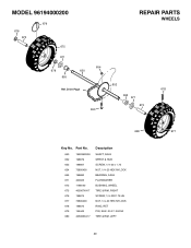
Part No. 650 199039X008 652 198679 653 198667 654 73800400 655 198680 671 400025 673 1199040 675 405067X417 676 198674 677 73800400 678 198675 679 155443 680 405066X417 Description SHAFT, AXLE SPRKT & HUB SCREW, 1/4--20 x 1.75 NUT, 1/4--20 HEX NYLOCK BEARING, AXLE FLATWASHER BUSHING, WHEEL TIRE & RIM, RIGHT SCREW, 1/4--20X1.75 HH NUT, 1/4--20 HEX NYLOCK RING, RET PIN, KLIK .25 X 1.38 DIA TIRE & RIM, LEFT 40 Drive Page 653 REPAIR PARTS WHEELS 652 676 655 671 673 680 677 Key No. MODEL 96194000200 678 673 679 675 671 678 655 654 650 Ref.
Part No. 650 199039X008 652 198679 653 198667 654 73800400 655 198680 671 400025 673 1199040 675 405067X417 676 198674 677 73800400 678 198675 679 155443 680 405066X417 Description SHAFT, AXLE SPRKT & HUB SCREW, 1/4--20 x 1.75 NUT, 1/4--20 HEX NYLOCK BEARING, AXLE FLATWASHER BUSHING, WHEEL TIRE & RIM, RIGHT SCREW, 1/4--20X1.75 HH NUT, 1/4--20 HEX NYLOCK RING, RET PIN, KLIK .25 X 1.38 DIA TIRE & RIM, LEFT 40 Drive Page 653 REPAIR PARTS WHEELS 652 676 655 671 673 680 677 Key No. MODEL 96194000200 678 673 679 675 671 678 655 654 650 Ref.
User Manual
Page 42
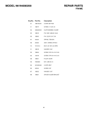
Part No. 90 198573X479 91 198574 103 406853X008 105 198576 106 198580 107 400024 108 405484 110 72110612 111 198578 122 198584 123 150078 148 198561 ..., BOTTOM SCREW, 1/4--20X .63 IDLER ASSEMBLY, AUGER PIN, HAIR .38DIAX1.64LG PIN, CLEVIS 3/16" DIA SPRING, TENSION ASSY., SPRING ATTACH BOLT, 3/8--16X1.25 CARR. MODEL 96194000200 REPAIR PARTS FRAME Key No. WASHER, FLAT SCREW, TAP 5/16--18 X 0.50 SCREW, TAP 5/16--18 X 0.75 PULLEY, IDLER NUT, JAM 3/8--16 COVER, BELT SCREW, TAP...
Part No. 90 198573X479 91 198574 103 406853X008 105 198576 106 198580 107 400024 108 405484 110 72110612 111 198578 122 198584 123 150078 148 198561 ..., BOTTOM SCREW, 1/4--20X .63 IDLER ASSEMBLY, AUGER PIN, HAIR .38DIAX1.64LG PIN, CLEVIS 3/16" DIA SPRING, TENSION ASSY., SPRING ATTACH BOLT, 3/8--16X1.25 CARR. MODEL 96194000200 REPAIR PARTS FRAME Key No. WASHER, FLAT SCREW, TAP 5/16--18 X 0.50 SCREW, TAP 5/16--18 X 0.75 PULLEY, IDLER NUT, JAM 3/8--16 COVER, BELT SCREW, TAP...
User Manual
Page 44
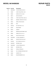
Part No. 200 198800X008 201 198588 206 198584 207 198815 208 198596 210 198819 212 198820 213 198822 215 73800400 217 405538 218 198592 220 198591 ... LOCK 3/8--24 RETAINER, RING LF ASSY, SPRING LINK YZ RETAINER, RING SPRING, EXTENSION WLD, INTERMED SPROCKET 33T/7 WASHER, FLAT RING,RETAINER(5100--50) 44 REPAIR PARTS DRIVE MODEL 96194000200 Key No.
Part No. 200 198800X008 201 198588 206 198584 207 198815 208 198596 210 198819 212 198820 213 198822 215 73800400 217 405538 218 198592 220 198591 ... LOCK 3/8--24 RETAINER, RING LF ASSY, SPRING LINK YZ RETAINER, RING SPRING, EXTENSION WLD, INTERMED SPROCKET 33T/7 WASHER, FLAT RING,RETAINER(5100--50) 44 REPAIR PARTS DRIVE MODEL 96194000200 Key No.
User Manual
Page 46
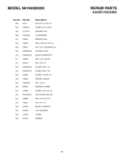
MODEL 96194000200 Key No. Part No. 480 45011 490 74950512 484 19111507 485 10040500 491 188909 493 199879 499 198541 500 405680X428 510 199045X479 511 198634 514 400100 520 405646X479 ... NUT, 1/4--20 BEARING, FLANGE SCREW, 5/16--18X .75 SKID, HEIGHT ADJUST BOLT, 5/16--18 X .75 NUT, 5/16--18 BRUSH, CLEANOUT CLIP, RETAINER SCREW WRENCH REPAIR PARTS AUGER HOUSING 46
MODEL 96194000200 Key No. Part No. 480 45011 490 74950512 484 19111507 485 10040500 491 188909 493 199879 499 198541 500 405680X428 510 199045X479 511 198634 514 400100 520 405646X479 ... NUT, 1/4--20 BEARING, FLANGE SCREW, 5/16--18X .75 SKID, HEIGHT ADJUST BOLT, 5/16--18 X .75 NUT, 5/16--18 BRUSH, CLEANOUT CLIP, RETAINER SCREW WRENCH REPAIR PARTS AUGER HOUSING 46
User Manual
Page 48
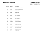
MODEL 96194000200 Key No. 582 Part No. 198661 584 751153 594 198662 596 198662 597 198851 599 198539 600 198842 601 198661 602 198662 603 73800500 606 1198659 607 405024 609 73800400 610 198831 611 198833 605 198844 Description BOLT, CARRIAGE 5/16--18 X.75 NUT, 5/16--18 REGHEX NYLOCK WASHER, FLAT WASHER, FLAT KNOB, T 3.00 BOLT, 5/16--18X1.00 CHUTE UPPER BOLT, 5/16--18 X1.00 WASHER, FLAT NUT, 5/16--18 HEXNYL CHUTE COLLAR SCREW, 1/4--20 X 0.75 NUT, 1/4--20 HEX NYLOCK RETAINER RING INNER RETAINER RING OUTER CHUTE LOWER REPAIR PARTS DISCHARGE CHUTE 48
MODEL 96194000200 Key No. 582 Part No. 198661 584 751153 594 198662 596 198662 597 198851 599 198539 600 198842 601 198661 602 198662 603 73800500 606 1198659 607 405024 609 73800400 610 198831 611 198833 605 198844 Description BOLT, CARRIAGE 5/16--18 X.75 NUT, 5/16--18 REGHEX NYLOCK WASHER, FLAT WASHER, FLAT KNOB, T 3.00 BOLT, 5/16--18X1.00 CHUTE UPPER BOLT, 5/16--18 X1.00 WASHER, FLAT NUT, 5/16--18 HEXNYL CHUTE COLLAR SCREW, 1/4--20 X 0.75 NUT, 1/4--20 HEX NYLOCK RETAINER RING INNER RETAINER RING OUTER CHUTE LOWER REPAIR PARTS DISCHARGE CHUTE 48
User Manual
Page 50
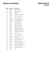
MODEL 96194000200 Key No. Part No. Description 720 400046X479 HANDLE, UPPER 724 198711 SCREW, 5/16--18X2.75 725 198662 WASHER, FLAT 726 10040500 WASHER, SPTLK .31X.58X.08 727 198683 ...--CABLE, AUGRT CLUTCH 760 198677X004 BRACKET, CABLE SPOOL YZ 762 406164 CABLE, LOWER DRIVE 12" 763 198673 BOLT, HEX 1/4--20 X 1.50 766 400047 GRIP REPAIR PARTS HANDLE 50
MODEL 96194000200 Key No. Part No. Description 720 400046X479 HANDLE, UPPER 724 198711 SCREW, 5/16--18X2.75 725 198662 WASHER, FLAT 726 10040500 WASHER, SPTLK .31X.58X.08 727 198683 ...--CABLE, AUGRT CLUTCH 760 198677X004 BRACKET, CABLE SPOOL YZ 762 406164 CABLE, LOWER DRIVE 12" 763 198673 BOLT, HEX 1/4--20 X 1.50 766 400047 GRIP REPAIR PARTS HANDLE 50
User Manual
Page 52
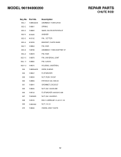
MODEL 96194000200 Key No. Part No. 852--1 198853x008 852--2 198861 852--3 198862 852--4 400026 852--5 400192 852--6 405339 852--7 198863 852--8 198788 852--9 198678 852--10 198878 852--11 198860 ... 3/8--16X6.00 GROMMET, EYE BOLT NUT, 3/8--16 HEXJAM FLATWASHER .406X.81X.066 NUT, 3/8--16 HEXNYL BOLT, CARRIAGE 1/4--20 X 1.00 NUT, 1/4--20 CRANK, ASSY CHUTE REPAIR PARTS CHUTE ROD 52
MODEL 96194000200 Key No. Part No. 852--1 198853x008 852--2 198861 852--3 198862 852--4 400026 852--5 400192 852--6 405339 852--7 198863 852--8 198788 852--9 198678 852--10 198878 852--11 198860 ... 3/8--16X6.00 GROMMET, EYE BOLT NUT, 3/8--16 HEXJAM FLATWASHER .406X.81X.066 NUT, 3/8--16 HEXNYL BOLT, CARRIAGE 1/4--20 X 1.00 NUT, 1/4--20 CRANK, ASSY CHUTE REPAIR PARTS CHUTE ROD 52
User Manual
Page 53
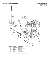
MODEL 96194000200 796 790 792 800 801 791 814 792 812 Key No. 790 791 792 796 800 801 812 813 814 Part No. 198725x479 198727 73800400 198736 198737 198727 198732x008 198945 198791 Description ROD, SHIFT SCREW, 1/4--20X.75 NUT, 1/4--20 KNOB, SLIP LEVER, SPRING SCREW, 1/4--20X.75 ROD ASSY., SPEED SELECT RETAINER, RING BEARING, FLANGED 53 REPAIR PARTS SHIFT YOKE 813
MODEL 96194000200 796 790 792 800 801 791 814 792 812 Key No. 790 791 792 796 800 801 812 813 814 Part No. 198725x479 198727 73800400 198736 198737 198727 198732x008 198945 198791 Description ROD, SHIFT SCREW, 1/4--20X.75 NUT, 1/4--20 KNOB, SLIP LEVER, SPRING SCREW, 1/4--20X.75 ROD ASSY., SPEED SELECT RETAINER, RING BEARING, FLANGED 53 REPAIR PARTS SHIFT YOKE 813


