
User Manual
Page 3
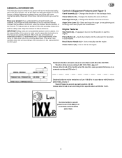
... the snow is correctly assembled. Recoil Starter Handle (12) -- If equipped, move to the ON position to the unit. Changes the distance the snow is written for future reference. Primer Button (9) -- Choke Control (14) -- Auger Drive Lever (5) -- Use to EN 1033;1996: 2,5 m/s2. Values determined at the handle when the machine was operated stationary on how to start the engine. GENERAL INFORMATION This instruction book is thrown. Like most service...
... the snow is correctly assembled. Recoil Starter Handle (12) -- If equipped, move to the ON position to the unit. Changes the distance the snow is written for future reference. Primer Button (9) -- Choke Control (14) -- Auger Drive Lever (5) -- Use to EN 1033;1996: 2,5 m/s2. Values determined at the handle when the machine was operated stationary on how to start the engine. GENERAL INFORMATION This instruction book is thrown. Like most service...
User Manual
Page 4
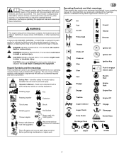
... Slow Fast Engage Engage Ignition On Ignition Off Ignition Key Push to the equipment. Auger Collector Engage Auger Clutch Disengage Drive Clutch Discharge Chute Heated Grips Chute Deflector LEFT RIGHT UP DOWN 4 In addition, a hazard symbol may be used without the alert symbol, indicates a situation that you . Review and understand the meanings. Oil Fuel On Off Primer bulb Foward Neutral Reverse Throttle Choke off engine and remove spark plug connector before performing...
... Slow Fast Engage Engage Ignition On Ignition Off Ignition Key Push to the equipment. Auger Collector Engage Auger Clutch Disengage Drive Clutch Discharge Chute Heated Grips Chute Deflector LEFT RIGHT UP DOWN 4 In addition, a hazard symbol may be used without the alert symbol, indicates a situation that you . Review and understand the meanings. Oil Fuel On Off Primer bulb Foward Neutral Reverse Throttle Choke off engine and remove spark plug connector before performing...
User Manual
Page 5
... not overload the machine capacity by the manufacturer for all moving parts. a. Fill fuel tank outdoors with a portable container, rather than from the spark plug, disconnect the cord on a truck or trailer bed with electric drive motors or electric starting the engine (motor). 3. Never fill containers inside a vehicle or on electric motors, thoroughly inspect snowthrower for Snowthrowers IMPORTANT: Safety standards require operator presence controls to make certain the...
... not overload the machine capacity by the manufacturer for all moving parts. a. Fill fuel tank outdoors with a portable container, rather than from the spark plug, disconnect the cord on a truck or trailer bed with electric drive motors or electric starting the engine (motor). 3. Never fill containers inside a vehicle or on electric motors, thoroughly inspect snowthrower for Snowthrowers IMPORTANT: Safety standards require operator presence controls to make certain the...
User Manual
Page 6
... for the relevant Emissions Durability Period and Air Index information on all settings and adjustments. 17. Run the machine a few minutes after transportation or storage. 8. Always follow the engine manual instructions for proper tightness to cause cancer, birth defects, or reproductive harm. 2. Check control operation frequently. This spark ignition system complies with safety devices. Never use a clean out tool, not your hand to be stored...
... for the relevant Emissions Durability Period and Air Index information on all settings and adjustments. 17. Run the machine a few minutes after transportation or storage. 8. Always follow the engine manual instructions for proper tightness to cause cancer, birth defects, or reproductive harm. 2. Check control operation frequently. This spark ignition system complies with safety devices. Never use a clean out tool, not your hand to be stored...
User Manual
Page 7
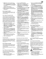
... spark plug. Tighten all parts that secure the drift cutters (1) to the auger housing. 2. If the bottom of the cables have become disconnected, reinstall the cables. 2. (Figure 10) If the top of snow toward bystanders. When inside of the flange (2). 3. See the engine manufacturer's instructions for the type of fuel and oil to use . Do not discard any assembly or maintenance to the snow thrower, remove the wire from the drive levers (6), attach...
... spark plug. Tighten all parts that secure the drift cutters (1) to the auger housing. 2. If the bottom of the cables have become disconnected, reinstall the cables. 2. (Figure 10) If the top of snow toward bystanders. When inside of the flange (2). 3. See the engine manufacturer's instructions for the type of fuel and oil to use . Do not discard any assembly or maintenance to the snow thrower, remove the wire from the drive levers (6), attach...
User Manual
Page 8
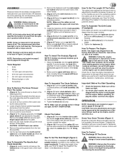
... Adjust The Clutch Cable" in severe eye damage. See "How To Adjust The Height Of The Skids" in the locked position (2). 2. How To Start The Engine (Figure 1) Models equipped with the snow thrower. Make sure that all times to avoid the possibility of this manual. 3. Check the engine oil. 2. Fill the fuel tank with a three--wire power cord and plug and is 14 PSI (1 BAR) to 17 PSI (1.25 BAR). Slowly return the recoil starter handle...
... Adjust The Clutch Cable" in severe eye damage. See "How To Adjust The Height Of The Skids" in the locked position (2). 2. How To Start The Engine (Figure 1) Models equipped with the snow thrower. Make sure that all times to avoid the possibility of this manual. 3. Check the engine oil. 2. Fill the fuel tank with a three--wire power cord and plug and is 14 PSI (1 BAR) to 17 PSI (1.25 BAR). Slowly return the recoil starter handle...
User Manual
Page 9
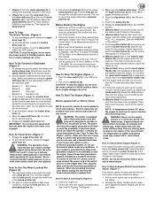
... the carburetor cover in deep, freezing or wet snow. ing (4) or the discharge chute (3). 5. (Figure 21) Use the clean--out tool (1) or a pry bar to remove any loose fasteners. See "How To Adjust The Height Of The Skids" in the engine manufacturer's instructions. Check Engine Oil Level Change Engine Oil Check And Tighten All Screws and Nuts Check Spark Plug Adjust Drive Belt Check Fuel Drain Fuel Check Auger Clutch Cable Adjustment (See Cable Adjustment) Check Traction Clutch Cable Adjustment (See Cable Adjustment) Lubricate All Pivot Points Lubricate Auger Shaft (See Shear Bolt...
... the carburetor cover in deep, freezing or wet snow. ing (4) or the discharge chute (3). 5. (Figure 21) Use the clean--out tool (1) or a pry bar to remove any loose fasteners. See "How To Adjust The Height Of The Skids" in the engine manufacturer's instructions. Check Engine Oil Level Change Engine Oil Check And Tighten All Screws and Nuts Check Spark Plug Adjust Drive Belt Check Fuel Drain Fuel Check Auger Clutch Cable Adjustment (See Cable Adjustment) Check Traction Clutch Cable Adjustment (See Cable Adjustment) Lubricate All Pivot Points Lubricate Auger Shaft (See Shear Bolt...
User Manual
Page 10
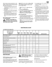
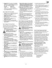
... cleared. 5. Lubrication Every 10 Hours (Figure 14) 1. Each time a shear bolt is adjusted or replaced, check and adjust the cable. Lubricate all safety and instruction decals and labels. Remove the gas from the gas tank. Remove the bottom panel (2). 5. (Figure 15) Lubricate the chains (5) with 5W30 motor oil. Clean off the cable adjustment bracket (4). 6. Tighten the bolts (3) on each season. Put the snow thrower on a level surface. 2. Make sure both tires are lifetime lubricated...
... cleared. 5. Lubrication Every 10 Hours (Figure 14) 1. Each time a shear bolt is adjusted or replaced, check and adjust the cable. Lubricate all safety and instruction decals and labels. Remove the gas from the gas tank. Remove the bottom panel (2). 5. (Figure 15) Lubricate the chains (5) with 5W30 motor oil. Clean off the cable adjustment bracket (4). 6. Tighten the bolts (3) on each season. Put the snow thrower on a level surface. 2. Make sure both tires are lifetime lubricated...
User Manual
Page 11
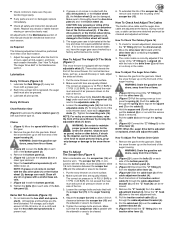
... gas tank. Install the new auger drive belt (4) onto the auger drive pulley (10). 11. Assemble the auger housing (22) to wear or stretch, proceed as follows. 1. Tighten screw (2). 17. Connect the spark plug wire. Disconnect the spark plug wire. 2. Adjust the belt guide (9). Tighten screw (2). 16. Check the adjustment of the bot- How To Adjust The Belt Guide 1. See "How To Replace the Friction Wheel" in the Maintenance section. If you need to adjust the belts due to the motor box (23) with the four bolts...
... gas tank. Install the new auger drive belt (4) onto the auger drive pulley (10). 11. Assemble the auger housing (22) to wear or stretch, proceed as follows. 1. Tighten screw (2). 17. Connect the spark plug wire. Disconnect the spark plug wire. 2. Adjust the belt guide (9). Tighten screw (2). 16. Check the adjustment of the bot- How To Adjust The Belt Guide 1. See "How To Replace the Friction Wheel" in the Maintenance section. If you need to adjust the belts due to the motor box (23) with the four bolts...
User Manual
Page 12
..., use plastic. Extra shear bolts were provided in the auger shaft. Connect the spark plug wire. Fill the engine crankcase with the fasteners removed earlier. Cover the bare metal parts of the friction wheel. If the machine must be sure the entire machine is off the hex shaft (8). 12. Do not use only original equipment shear bolts. Do not use a harder bolt as follows: Tire Size Distance "A" 12 and 13 inch...
..., use plastic. Extra shear bolts were provided in the auger shaft. Connect the spark plug wire. Fill the engine crankcase with the fasteners removed earlier. Cover the bare metal parts of the friction wheel. If the machine must be sure the entire machine is off the hex shaft (8). 12. Do not use only original equipment shear bolts. Do not use a harder bolt as follows: Tire Size Distance "A" 12 and 13 inch...
User Manual
Page 13
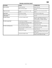
... of auger housing. Use carburetor bowl drain to flush and refill with fresh fuel. Adjust auger control cable. Auger control cable not adjusted correctly. Clean fuel line; add fresh gasoline Set choke lever to discharge snow GB TROUBLE SHOOTING CHART CAUSE Defective spark plug. Tighten all bolts and make all necessary repairs. Replace drive belt. Remove object from auger. 13 Shear bolt broken Discharge chute clogged. Stop engine immediately and disconnect spark plug wire. If vibration continues, have the unit serviced by a competent repairman. Replace friction wheel...
... of auger housing. Use carburetor bowl drain to flush and refill with fresh fuel. Adjust auger control cable. Auger control cable not adjusted correctly. Clean fuel line; add fresh gasoline Set choke lever to discharge snow GB TROUBLE SHOOTING CHART CAUSE Defective spark plug. Tighten all bolts and make all necessary repairs. Replace drive belt. Remove object from auger. 13 Shear bolt broken Discharge chute clogged. Stop engine immediately and disconnect spark plug wire. If vibration continues, have the unit serviced by a competent repairman. Replace friction wheel...
User Manual
Page 14
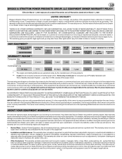
... parts that is correctly assembled. Accessory parts such as quick couplers, oil gauges, belts, o-rings, filters, pump packing, etc., pumps that , upon examination, is found to be defective under this warranty must carefully check the unit according to ensure assembly is effective for consumer use of the owner to the instructions in the Operating & Maintenance Instructions before March 1, 2005 LIMITED WARRANTY Briggs & Stratton Power Products Group, LLC will repair or replace any part...
... parts that is correctly assembled. Accessory parts such as quick couplers, oil gauges, belts, o-rings, filters, pump packing, etc., pumps that , upon examination, is found to be defective under this warranty must carefully check the unit according to ensure assembly is effective for consumer use of the owner to the instructions in the Operating & Maintenance Instructions before March 1, 2005 LIMITED WARRANTY Briggs & Stratton Power Products Group, LLC will repair or replace any part...
User Manual
Page 38
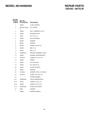
... 198580 SPRING 17 198561 PULLEY, IDLER 18 198562 NUT, JAM 3/8--16 20 198555 GUIDE, ROD BELT 21 400025 WASHER 22 10040500 WASHER, SPTLK .31X.58X.08 24 74610516 SCREW, 5/16--24X 0.75 25 FRAME ASSEMBLY 25--1 198784X428 PLATE, ENGINE MOUNT 25--2 198574 SCREW 1/4--20 X .63 25--3 198584 SCREW 5/16--18 X .50 25--4 198766X428 FRAME, MOTOR BOX 27 59289 WASHER -- -- 406885 OWNER'S MANUAL 38 REPAIR PARTS ENGINE...
... 198580 SPRING 17 198561 PULLEY, IDLER 18 198562 NUT, JAM 3/8--16 20 198555 GUIDE, ROD BELT 21 400025 WASHER 22 10040500 WASHER, SPTLK .31X.58X.08 24 74610516 SCREW, 5/16--24X 0.75 25 FRAME ASSEMBLY 25--1 198784X428 PLATE, ENGINE MOUNT 25--2 198574 SCREW 1/4--20 X .63 25--3 198584 SCREW 5/16--18 X .50 25--4 198766X428 FRAME, MOTOR BOX 27 59289 WASHER -- -- 406885 OWNER'S MANUAL 38 REPAIR PARTS ENGINE...
User Manual
Page 39
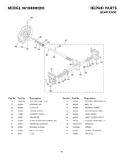
... PIN,SPRING SHAFT, AUGER INPUT (IMPELLER) GEARCASE,COMPLETE BUSHING, FLANGE BOLT 1/4--20 x 3/4 PLUG Key No. MODEL 96194000200 REPAIR PARTS GEAR CASE Key No. Part No. 41 404965 42 404959 43 404960 44 404952 45 404962 46 404946 47 404964 48 405027X479 49 74780426 50 404950 51 7B36M Description HOUSING, GEARCASE, RH SEAL, OIL BEARING, FLANGE KEY, WOODRUFF #605 GEAR, WORM SHAFT, AUGER OUTPUT HOUSING, GEARCASE, LH IMPELLER SCREW GASKET...
... PIN,SPRING SHAFT, AUGER INPUT (IMPELLER) GEARCASE,COMPLETE BUSHING, FLANGE BOLT 1/4--20 x 3/4 PLUG Key No. MODEL 96194000200 REPAIR PARTS GEAR CASE Key No. Part No. 41 404965 42 404959 43 404960 44 404952 45 404962 46 404946 47 404964 48 405027X479 49 74780426 50 404950 51 7B36M Description HOUSING, GEARCASE, RH SEAL, OIL BEARING, FLANGE KEY, WOODRUFF #605 GEAR, WORM SHAFT, AUGER OUTPUT HOUSING, GEARCASE, LH IMPELLER SCREW GASKET...
User Manual
Page 42
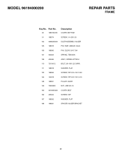
MODEL 96194000200 REPAIR PARTS FRAME Key No. WASHER, FLAT SCREW, TAP 5/16--18 X 0.50 SCREW, TAP 5/16--18 X 0.75 PULLEY, IDLER NUT, JAM 3/8--16 COVER, BELT SCREW, TAP WASHER, FLAT SPACER, AUGER BRACKET 42 Part No. 90 198573X479 91 198574 103 406853X008 105 198576 106 198580 107 400024 108 405484 110 72110612 111 198578 122 198584 123 150078 148 198561 ...
MODEL 96194000200 REPAIR PARTS FRAME Key No. WASHER, FLAT SCREW, TAP 5/16--18 X 0.50 SCREW, TAP 5/16--18 X 0.75 PULLEY, IDLER NUT, JAM 3/8--16 COVER, BELT SCREW, TAP WASHER, FLAT SPACER, AUGER BRACKET 42 Part No. 90 198573X479 91 198574 103 406853X008 105 198576 106 198580 107 400024 108 405484 110 72110612 111 198578 122 198584 123 150078 148 198561 ...
User Manual
Page 44
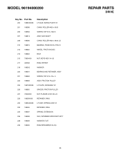
... #420 x19.00 SCREW, TAP 5/16--18x0.5 ASSY, HEX SHAFT CHAIN, ROLLER #420 x18.00 LG BEARING, TRUNION CLUTCH R WHEEL, FRICTION DISC BOLT NUT, KEPS HEX 1/4--20 RING, RETEXT WASHER BEARING AND RETAINER, ASSY SCREW, TAP 5/16--18 x .5 ASSY, FRICTION PULLEY LF PLATE, SWINGING YZ SPACER, FRICTION PULLEY NUT, FLANGE LOCK 3/8--24 RETAINER, RING LF ASSY, SPRING LINK YZ RETAINER, RING SPRING, EXTENSION WLD...
... #420 x19.00 SCREW, TAP 5/16--18x0.5 ASSY, HEX SHAFT CHAIN, ROLLER #420 x18.00 LG BEARING, TRUNION CLUTCH R WHEEL, FRICTION DISC BOLT NUT, KEPS HEX 1/4--20 RING, RETEXT WASHER BEARING AND RETAINER, ASSY SCREW, TAP 5/16--18 x .5 ASSY, FRICTION PULLEY LF PLATE, SWINGING YZ SPACER, FRICTION PULLEY NUT, FLANGE LOCK 3/8--24 RETAINER, RING LF ASSY, SPRING LINK YZ RETAINER, RING SPRING, EXTENSION WLD...
User Manual
Page 46
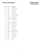
... .67 SCREW, 5/16--18X.63 WASHER, FLAT LOCKWASHER BEARING, BALL BOLT, HEX 5/16--18X .50 NUT, 5/16--18 HEXWDFLLK HOUSING, ASSY BLADE, SCRAPER 24" BOLT, 5/16--18x0.62 NUT, 5/16--18 AUGER, ASSY, LH AUGER, ASSY, RH SCREW, 1/4--20X1.75 SPACER, SLEEVE NUT, 1/4--20 BEARING, FLANGE SCREW, 5/16--18X .75 SKID, HEIGHT ADJUST BOLT, 5/16--18 X .75 NUT, 5/16--18 BRUSH, CLEANOUT CLIP, RETAINER SCREW WRENCH REPAIR PARTS AUGER HOUSING 46
... .67 SCREW, 5/16--18X.63 WASHER, FLAT LOCKWASHER BEARING, BALL BOLT, HEX 5/16--18X .50 NUT, 5/16--18 HEXWDFLLK HOUSING, ASSY BLADE, SCRAPER 24" BOLT, 5/16--18x0.62 NUT, 5/16--18 AUGER, ASSY, LH AUGER, ASSY, RH SCREW, 1/4--20X1.75 SPACER, SLEEVE NUT, 1/4--20 BEARING, FLANGE SCREW, 5/16--18X .75 SKID, HEIGHT ADJUST BOLT, 5/16--18 X .75 NUT, 5/16--18 BRUSH, CLEANOUT CLIP, RETAINER SCREW WRENCH REPAIR PARTS AUGER HOUSING 46
User Manual
Page 50
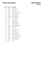
... 400050 CABLE, AUGER CLUTCH 743 198692 BRACKET, CABLE ADJUSTER 744 198690 SPRING, AUGER CLUTCH 745 73600400 NUT, 1/4--20 746 198670 BOOT, CLUTCH SPRING 750 400151X479 HANDLE, LOWER 751 150078 SCREW, TAP 5/16--18 X 0.75 755 198699X479 BRKT, GEAR SELECTOR 756 198574 SCREW, 1/4--20 X 0.63 759 198678 SPOOL--CABLE, AUGRT CLUTCH 760 198677X004 BRACKET, CABLE SPOOL YZ 762 406164 CABLE, LOWER DRIVE 12" 763 198673 BOLT, HEX 1/4--20 X 1.50 766 400047 GRIP REPAIR PARTS HANDLE 50 Part No. MODEL 96194000200...
... 400050 CABLE, AUGER CLUTCH 743 198692 BRACKET, CABLE ADJUSTER 744 198690 SPRING, AUGER CLUTCH 745 73600400 NUT, 1/4--20 746 198670 BOOT, CLUTCH SPRING 750 400151X479 HANDLE, LOWER 751 150078 SCREW, TAP 5/16--18 X 0.75 755 198699X479 BRKT, GEAR SELECTOR 756 198574 SCREW, 1/4--20 X 0.63 759 198678 SPOOL--CABLE, AUGRT CLUTCH 760 198677X004 BRACKET, CABLE SPOOL YZ 762 406164 CABLE, LOWER DRIVE 12" 763 198673 BOLT, HEX 1/4--20 X 1.50 766 400047 GRIP REPAIR PARTS HANDLE 50 Part No. MODEL 96194000200...
User Manual
Page 54
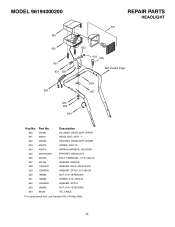
... Description HOUSING, HEADLIGHT UPPER HEADLIGHT, ASSY * HOUSING, HEADLIGHT LOWER SCREW, #8X1.75 WIRING HARNESS, HALOGEN BRACKET, HEADLIGHT BOLT, CARRIAGE -- 5/16--18X2.00 WASHER, SADDLE WASHER, EXLK .32X.60X.040 WASHER, SPTLK .31X.58X.08 NUT, 5/16--18 REGHEX SCREW, 5/16--18X2.00 WASHER, SPTLK NUT, 5/16--18 REGHEX TIE, CABLE * For replacement bulb, use Standard GE or Phillips #894. 54 MODEL 96194000200 620 REPAIR PARTS HEADLIGHT...
... Description HOUSING, HEADLIGHT UPPER HEADLIGHT, ASSY * HOUSING, HEADLIGHT LOWER SCREW, #8X1.75 WIRING HARNESS, HALOGEN BRACKET, HEADLIGHT BOLT, CARRIAGE -- 5/16--18X2.00 WASHER, SADDLE WASHER, EXLK .32X.60X.040 WASHER, SPTLK .31X.58X.08 NUT, 5/16--18 REGHEX SCREW, 5/16--18X2.00 WASHER, SPTLK NUT, 5/16--18 REGHEX TIE, CABLE * For replacement bulb, use Standard GE or Phillips #894. 54 MODEL 96194000200 620 REPAIR PARTS HEADLIGHT...
User Manual
Page 55
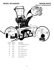
REAR AUGER HOUSING 55 MODEL 96194000200 830 829 831 REPAIR PARTS DECALS / AUTOCOLLANT SIDE OF ENGINE 828 827 REF. REAR VIEW Key No. Part No. 823 198525 824 198527 827 405990 828 198524 829 400082 830 400081 831 405883 -- -- -- 406885 Description DECAL, DANGER CHUTE HAND DECAL, DANGER FOOT DECAL, 6.5/24" DECAL, THROWN OBJECTS DECAL, DRIVE CLUTCH DECAL, AUGER CLUTCH DECAL, GEAR SELECTOR OWNERS MANUAL 828 823 824 REF.
REAR AUGER HOUSING 55 MODEL 96194000200 830 829 831 REPAIR PARTS DECALS / AUTOCOLLANT SIDE OF ENGINE 828 827 REF. REAR VIEW Key No. Part No. 823 198525 824 198527 827 405990 828 198524 829 400082 830 400081 831 405883 -- -- -- 406885 Description DECAL, DANGER CHUTE HAND DECAL, DANGER FOOT DECAL, 6.5/24" DECAL, THROWN OBJECTS DECAL, DRIVE CLUTCH DECAL, AUGER CLUTCH DECAL, GEAR SELECTOR OWNERS MANUAL 828 823 824 REF.


