

User Manual
Page 1
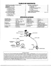
... Protection During Operation Model•• 1400 T • Tnynmer MANUFACTURED UNDER ONE OR MORE OF THE FOLLOWING U.S. DES.260.394. PATENTS: 3,708.967; 3,826,068; 3.859,776; DES.255,764; AND FOREIGN PATENTS PENDING. IMPORTANT MANUAL Do Not Throw Away TRADEMARK® OPERATOR'S MANUAL: AWARNING: Read the Operator's Manual and Follow All Warnings and Safety Instructions. O35.912...
... Protection During Operation Model•• 1400 T • Tnynmer MANUFACTURED UNDER ONE OR MORE OF THE FOLLOWING U.S. DES.260.394. PATENTS: 3,708.967; 3,826,068; 3.859,776; DES.255,764; AND FOREIGN PATENTS PENDING. IMPORTANT MANUAL Do Not Throw Away TRADEMARK® OPERATOR'S MANUAL: AWARNING: Read the Operator's Manual and Follow All Warnings and Safety Instructions. O35.912...
User Manual
Page 2
... for the prevention offire. Check with adjustable fuel mixture jets Push Button Auto Rewind FUEL TANK: SPARK PLUG: SPARK PLUG GAP: MODULE AIR GAP: LUBRICATION: CUTTING LINE: MUFFLER: 13.5 fl. This unit is available as an optional part. Cutting Methods D. Carburetor Adjustments 10 E. Starter Rope 9 C. Trouble Shooting Chart 1 I WEED EX11.110 ACCESSORIES 11 PARIS AND SERVICE 12 12 13 14 SPECIFICATIONS 15 15 16 17 18 18 19 19 Back Cover ENGINE TYPE: DISPLACEMENT: ENGINE RPM: IGNITION: CARBURETOR: ENGINE "OFF": STARTER: 2-Cycle, Air-Cooled 22.2 cc...
... for the prevention offire. Check with adjustable fuel mixture jets Push Button Auto Rewind FUEL TANK: SPARK PLUG: SPARK PLUG GAP: MODULE AIR GAP: LUBRICATION: CUTTING LINE: MUFFLER: 13.5 fl. This unit is available as an optional part. Cutting Methods D. Carburetor Adjustments 10 E. Starter Rope 9 C. Trouble Shooting Chart 1 I WEED EX11.110 ACCESSORIES 11 PARIS AND SERVICE 12 12 13 14 SPECIFICATIONS 15 15 16 17 18 18 19 19 Back Cover ENGINE TYPE: DISPLACEMENT: ENGINE RPM: IGNITION: CARBURETOR: ENGINE "OFF": STARTER: 2-Cycle, Air-Cooled 22.2 cc...
User Manual
Page 3
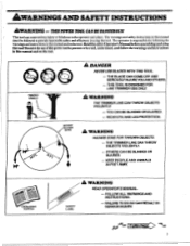
... thistool!Restrictthe useof thispower toolto personswhoread, understand,and followthewarningsand instructions in using this manual and on the tool. 0 0 ADANENVEG--REULSTTRSIHNEIESHBEBLTRAREDOLMELIMSIIAESCOWNRDDIUETASHUJCIEGTESNUYOHNSONEISLDOORTYALFOMOYEUFNOALOEFNDRTDHERS. THROWN OBJECT A WARNING --WYOCEEUAABYANRBEENLLDEIPNOGRDIRNOEJDTUERCETDIO. N THETRIMMERLINECANTHROWOBJECTS VIOLENTLY. 60 FOOT f Thistoolcan causeserious injuryorblindnesstothe operator and others. The warningsand safety instructions in this manual must be followed to provide reasonable safety and efficiency in...
... thistool!Restrictthe useof thispower toolto personswhoread, understand,and followthewarningsand instructions in using this manual and on the tool. 0 0 ADANENVEG--REULSTTRSIHNEIESHBEBLTRAREDOLMELIMSIIAESCOWNRDDIUETASHUJCIEGTESNUYOHNSONEISLDOORTYALFOMOYEUFNOALOEFNDRTDHERS. THROWN OBJECT A WARNING --WYOCEEUAABYANRBEENLLDEIPNOGRDIRNOEJDTUERCETDIO. N THETRIMMERLINECANTHROWOBJECTS VIOLENTLY. 60 FOOT f Thistoolcan causeserious injuryorblindnesstothe operator and others. The warningsand safety instructions in this manual must be followed to provide reasonable safety and efficiency in...

User Manual
Page 5
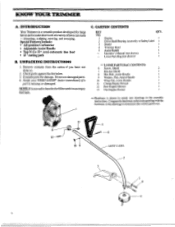
... the carburetor by the drive shaft housing. 6. Stop engine before starting engine. 5. Hold the tool firmly with the drive shaft housing supported to cool, empty the fuel tank, and secure the tool before performing maintenance except for more of children. Keepall partsofyour body away from objects that are no sparks or flames. 2. Contactyourdealerifyou need assistance. 5 Use only WEED EATER° flexible, non-metallic, monofilament cutting line of oil and fuel. Never use the assist handle. Hold the tool...
... the carburetor by the drive shaft housing. 6. Stop engine before starting engine. 5. Hold the tool firmly with the drive shaft housing supported to cool, empty the fuel tank, and secure the tool before performing maintenance except for more of children. Keepall partsofyour body away from objects that are no sparks or flames. 2. Contactyourdealerifyou need assistance. 5 Use only WEED EATER° flexible, non-metallic, monofilament cutting line of oil and fuel. Never use the assist handle. Hold the tool...
User Manual
Page 6
... use. 10 9 _5 _8 SAFETY LABEL 6 Check parts against the list below. 3. Notify your WEED EATERe dealer immediately ifa pan is shown in actual size drawings in the drawings to determine the correct part to hearthefuel filter rattleinan empty fuel tank. Remove contents from the carton if you have not done so. 2. Donot usedamaged parts. 4. Engine Drive Shaft/Bearing Assembly w/Safety Label Shield Trimmer Head Assist Handle Operator's Manual (not shown) Loose Parts...
... use. 10 9 _5 _8 SAFETY LABEL 6 Check parts against the list below. 3. Notify your WEED EATERe dealer immediately ifa pan is shown in actual size drawings in the drawings to determine the correct part to hearthefuel filter rattleinan empty fuel tank. Remove contents from the carton if you have not done so. 2. Donot usedamaged parts. 4. Engine Drive Shaft/Bearing Assembly w/Safety Label Shield Trimmer Head Assist Handle Operator's Manual (not shown) Loose Parts...
User Manual
Page 7
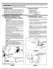
... Trimmer Head and tighten more securely. d. t MARK I -1/4" WRENCH DIRECTION ID INSTALL ARBOR SHAFT DUST CUP Figure 2 Approximately 2 inches of line can unthread the first time the engine is important that you will significantly reduce the life of the Drive Shaft Housing. TRIMMER ASSEMBLY STEPS 1 *DRIVE SHAFT HOUSING Figure 1 a. Mark a line 1-1/2 inches from the end of the Drive Shaft Housing when the packing cover is adjusted for the operator.) A. d. f. NUT \ FLEXIBLE coy DRIVE SHAFT a KEYWAY KEY 2. Tape Measure & Grease...
... Trimmer Head and tighten more securely. d. t MARK I -1/4" WRENCH DIRECTION ID INSTALL ARBOR SHAFT DUST CUP Figure 2 Approximately 2 inches of line can unthread the first time the engine is important that you will significantly reduce the life of the Drive Shaft Housing. TRIMMER ASSEMBLY STEPS 1 *DRIVE SHAFT HOUSING Figure 1 a. Mark a line 1-1/2 inches from the end of the Drive Shaft Housing when the packing cover is adjusted for the operator.) A. d. f. NUT \ FLEXIBLE coy DRIVE SHAFT a KEYWAY KEY 2. Tape Measure & Grease...

User Manual
Page 8
... BOLT SAFETY LABELS Figure 5 RIGHT ARM SLIGHTLY BENT. CAUTION: The Line Limiter is fully tightened. 4. d. Figure 5. Before starting the Engine, stand as a ditch bank. Left arm fully extended, hand holding the Rear Handle, and fingers on the Drive Shaft Housing. Figure 4(Inset). Hold the Assist Handle and with the Keyway ("V" slot) on Throttle Trigger. 3). Install the Washer and Wing Nut. Weight of tool evenly...
... BOLT SAFETY LABELS Figure 5 RIGHT ARM SLIGHTLY BENT. CAUTION: The Line Limiter is fully tightened. 4. d. Figure 5. Before starting the Engine, stand as a ditch bank. Left arm fully extended, hand holding the Rear Handle, and fingers on the Drive Shaft Housing. Figure 4(Inset). Hold the Assist Handle and with the Keyway ("V" slot) on Throttle Trigger. 3). Install the Washer and Wing Nut. Weight of tool evenly...
User Manual
Page 9
... for air-cooled 2-cycle engines and can cause damage. 5.HOW TO MIX FUEL AND FILL TANK a. Stop engine before starting engine. Store tool and fuel in thefuel tank. 3.USE THE FOLLOWING: Poulan Weed EaterT" 40:1 Engine Oil is strongly recommended for location. CAUTION: Too little oil or incorrect oil will chemically breakdown and form compounds that Poulan/Weed Eater oil resists breakdown at a ratio of your unit. ENGINE INFORMATION A. The internal design of America) - Slowly remove fuel container cover. c. g. FUELING YOUR ENGINE 1.. After...
... for air-cooled 2-cycle engines and can cause damage. 5.HOW TO MIX FUEL AND FILL TANK a. Stop engine before starting engine. Store tool and fuel in thefuel tank. 3.USE THE FOLLOWING: Poulan Weed EaterT" 40:1 Engine Oil is strongly recommended for location. CAUTION: Too little oil or incorrect oil will chemically breakdown and form compounds that Poulan/Weed Eater oil resists breakdown at a ratio of your unit. ENGINE INFORMATION A. The internal design of America) - Slowly remove fuel container cover. c. g. FUELING YOUR ENGINE 1.. After...
User Manual
Page 10
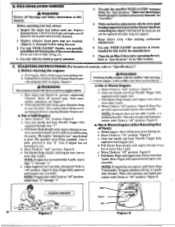
... procedure with Chokeat "off ' position. b. Figure 8. ably flooded. Replace damaged parts. Keep others away when making carburetor adjustments. 8. With optional Shoulder Strap, place Shoulder Strap on engine. Figure 8. PRE-OPERATION CHECKS A WARNING Review all fasteners are cracked, chipped, or damaged before using this tool by hand;do not use wire or rope, string, etc. 4. Use only WEED EATER® accessories as engine starts. Pull Starter Rope until engine attempts to pro- position, repeat steps "d" through "e." 3. Wait...
... procedure with Chokeat "off ' position. b. Figure 8. ably flooded. Replace damaged parts. Keep others away when making carburetor adjustments. 8. With optional Shoulder Strap, place Shoulder Strap on engine. Figure 8. PRE-OPERATION CHECKS A WARNING Review all fasteners are cracked, chipped, or damaged before using this tool by hand;do not use wire or rope, string, etc. 4. Use only WEED EATER® accessories as engine starts. Pull Starter Rope until engine attempts to pro- position, repeat steps "d" through "e." 3. Wait...

User Manual
Page 11
... cutting line will not provide complete protection to be cut. If the Trimmer Head does not turn when the engine is accelerated, make sure the Drive Shaft Housing is properly seated in any way can fly apart and cause serious injury. The shield will cut . I . Keep others . Hold button down until the engine stops. Replace damaged parts before using the tool. 11 a. Refer to `Assembly-Drive Shaft Housing!' 2. Figure 9. D. The operator...
... cutting line will not provide complete protection to be cut. If the Trimmer Head does not turn when the engine is accelerated, make sure the Drive Shaft Housing is properly seated in any way can fly apart and cause serious injury. The shield will cut . I . Keep others . Hold button down until the engine stops. Replace damaged parts before using the tool. 11 a. Refer to `Assembly-Drive Shaft Housing!' 2. Figure 9. D. The operator...
User Manual
Page 12
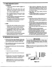
... when making carburetor adjustments. g. h. See Figure 10. f. Be sure the shield is above the grassy area. 3. Hold the tool with the drive shaft housing supported to the trimmer head. d. Do not raise the engine above your body. Operate the engine at full throttle. • The most efficient line length. 12 AWARNING Use only .080" diameter Weed Eater® Trimmer Line. See "Accessories." Do not operate this tool by the line limiter. •...
... when making carburetor adjustments. g. h. See Figure 10. f. Be sure the shield is above the grassy area. 3. Hold the tool with the drive shaft housing supported to the trimmer head. d. Do not raise the engine above your body. Operate the engine at full throttle. • The most efficient line length. 12 AWARNING Use only .080" diameter Weed Eater® Trimmer Line. See "Accessories." Do not operate this tool by the line limiter. •...

User Manual
Page 13
... 14 Your trimmer is ideal formowing in Figure 11. • The line will easily remove grass and weeds from side to turn when the engine is good for a quickand easy clean up. Keep the line parallel toand above the surfaces being swept and move the tool from around...good clean job. • Avoid letting the trimmer head continuously contact the ground during light duty cutting. - The rightand wrong way are shown in placesconventional lawn mowers cannot reach. Never lean over the trim- during normal cutting. In the mowing position, keep the line parallel to do the cutting. ...
... 14 Your trimmer is ideal formowing in Figure 11. • The line will easily remove grass and weeds from side to turn when the engine is good for a quickand easy clean up. Keep the line parallel toand above the surfaces being swept and move the tool from around...good clean job. • Avoid letting the trimmer head continuously contact the ground during light duty cutting. - The rightand wrong way are shown in placesconventional lawn mowers cannot reach. Never lean over the trim- during normal cutting. In the mowing position, keep the line parallel to do the cutting. ...

User Manual
Page 14
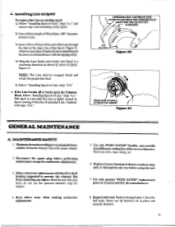
... and pulling on the Line to turn clockwise elk . h. Turn Lock Ring counterclockwise *UR. Remove the Lock Ring and Spool. Replace damaged parts before using the tool. Then test the Lock Ring by trying to change the Spool from the Trimmer Head. g. Pull on it counterclockwise AWARNING All three catches must be pulled from the locked position to replace LOCK TAB Figure 16 SPOOL CATCHES HUB 4 a .at LOCK RIM; I -Installing Spool fl ing a. LINE REPLACEMENT • For proper line feed: - Clean...
... and pulling on the Line to turn clockwise elk . h. Turn Lock Ring counterclockwise *UR. Remove the Lock Ring and Spool. Replace damaged parts before using the tool. Then test the Lock Ring by trying to change the Spool from the Trimmer Head. g. Pull on it counterclockwise AWARNING All three catches must be pulled from the locked position to replace LOCK TAB Figure 16 SPOOL CATCHES HUB 4 a .at LOCK RIM; I -Installing Spool fl ing a. LINE REPLACEMENT • For proper line feed: - Clean...
User Manual
Page 15
... GENERAL MAINTENANCE A. Disconnect the spark plug before using the tool. 7. Replacetrirrunerhead partsthatarecracked, chipped,or damaged in Line until the Line is tightly wound on Spool, leaving4-6 inches ofextended Line. Use only genuine WEED EATER® replacement parts as shown by the manufacturer. 8. Check for supper• 4. Make sure all fasteners are in the Trimmer Head, follow "Installing Spool w/Line," steps "a-c." and remove any Line remaining on the spool. 2).Use a 40 foot length of Weed Eater .080"diameter trimmer Line...
... GENERAL MAINTENANCE A. Disconnect the spark plug before using the tool. 7. Replacetrirrunerhead partsthatarecracked, chipped,or damaged in Line until the Line is tightly wound on Spool, leaving4-6 inches ofextended Line. Use only genuine WEED EATER® replacement parts as shown by the manufacturer. 8. Check for supper• 4. Make sure all fasteners are in the Trimmer Head, follow "Installing Spool w/Line," steps "a-c." and remove any Line remaining on the spool. 2).Use a 40 foot length of Weed Eater .080"diameter trimmer Line...
User Manual
Page 16
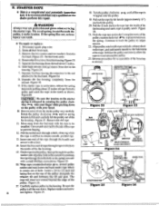
... the handle (approximately 12 ") and hold the pulley to the full extent of rope from tank. 3. Figure 26. 17. until no spring tension is felt and carefully lift the pulley out of hole. Pull the12 inch slack inthe rope intothe insideofthe fan housing and catch rope in the housing. Continue to prevent fraying. 12. REMOVE THE FIVE SCREWS AIR FILTER REMOVE SCREW REMOVE SCREW Figure 22 FUEL LINE FAN HOUSING Figure 23 IGNITION MODULE...
... the handle (approximately 12 ") and hold the pulley to the full extent of rope from tank. 3. Figure 26. 17. until no spring tension is felt and carefully lift the pulley out of hole. Pull the12 inch slack inthe rope intothe insideofthe fan housing and catch rope in the housing. Continue to prevent fraying. 12. REMOVE THE FIVE SCREWS AIR FILTER REMOVE SCREW REMOVE SCREW Figure 22 FUEL LINE FAN HOUSING Figure 23 IGNITION MODULE...

User Manual
Page 17
PULLEY SCREW PUL>L/ RATCHET WTI ROPE PULLEY GROOVE PULLEY NOTCH HOLE Figure 27 ROPE GROOVE 0. 0 Figure 28 C. CAUTION: Lay the Flexible Drive Shaft on any old grease. Even after re-assembly iscompleted. Using a clean cloth, wipe the surface of the Flexible Drive Shaft. 6. Figure 30. 5. Apply a uniform coat of lube to the entire surface of the Flexible Drive Shaft thoroughly to replace Drive Shaft Housing into the top of operation. - Figure 24...
PULLEY SCREW PUL>L/ RATCHET WTI ROPE PULLEY GROOVE PULLEY NOTCH HOLE Figure 27 ROPE GROOVE 0. 0 Figure 28 C. CAUTION: Lay the Flexible Drive Shaft on any old grease. Even after re-assembly iscompleted. Using a clean cloth, wipe the surface of the Flexible Drive Shaft. 6. Figure 30. 5. Apply a uniform coat of lube to the entire surface of the Flexible Drive Shaft thoroughly to replace Drive Shaft Housing into the top of operation. - Figure 24...
User Manual
Page 18
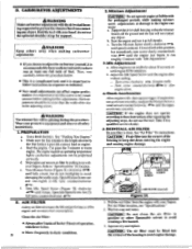
.... Use a fresh fuel mix. b. a. donot use the tool. Start the engine. c. Take it at idle for instructions. [CAUTION: Fitairfilterintothecornersof the housing to run at full throttle. e. Pull the Air Filter from the engine with "Idle Adjustment." 3. For Air Filter location, see "Specifications?' 2. Continue with your fingers. b. D. E. Allow engine to keep dirt€rom entering the engine and causing engine damage. 0 IDLE MIXTURE SPEED SCREW SCREW , 4-4 ptitVa$ .,1:ta AIR FILTER (removed) Figure 31 1. CAUTION: j If the engine does not operate accentingto...
.... Use a fresh fuel mix. b. a. donot use the tool. Start the engine. c. Take it at idle for instructions. [CAUTION: Fitairfilterintothecornersof the housing to run at full throttle. e. Pull the Air Filter from the engine with "Idle Adjustment." 3. For Air Filter location, see "Specifications?' 2. Continue with your fingers. b. D. E. Allow engine to keep dirt€rom entering the engine and causing engine damage. 0 IDLE MIXTURE SPEED SCREW SCREW , 4-4 ptitVa$ .,1:ta AIR FILTER (removed) Figure 31 1. CAUTION: j If the engine does not operate accentingto...
User Manual
Page 19
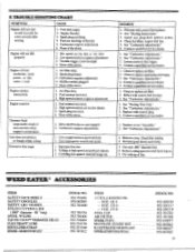
Idle speed set too low (lean). 3. Spark plug fouled. 3. Fuel mixture incorrect. 2. Line caught between spool and hub. 2. Cutting at high speed around hard objects. 3. Install new plug/check ignition system. 4. Clean fuel filter, inspect fuel line. 5. Contact a qualified service dealer. 1. Clean or replace spark plug and regap. 3. Contact a qualified service dealer. 1. See "Fueling Your Unit?' 2. Replace or see "Assembly." 2. Carburetor requires adjustment. ,--6. None of the above . 1. Trimmer head stops under a load Engine smokes excessively Engine runs hot...
Idle speed set too low (lean). 3. Spark plug fouled. 3. Fuel mixture incorrect. 2. Line caught between spool and hub. 2. Cutting at high speed around hard objects. 3. Install new plug/check ignition system. 4. Clean fuel filter, inspect fuel line. 5. Contact a qualified service dealer. 1. Clean or replace spark plug and regap. 3. Contact a qualified service dealer. 1. See "Fueling Your Unit?' 2. Replace or see "Assembly." 2. Carburetor requires adjustment. ,--6. None of the above . 1. Trimmer head stops under a load Engine smokes excessively Engine runs hot...
User Manual
Page 20
...530-067065-4-11788 PARTS AND SERVICE Your Poulan /Weed Eater product has been expertly engineered and carefully manufactured to safety. Alwaysupdateyourtool whenimprovementsare madeavailable, especially those described in this Operator's Manual, pleasecontactyourlocal Poulan/Weed Eater Dealer for trinuners,Brushcutters,and Blowers) or Skil Service Center (under "tools-electric"). 2. b. Consulttheyellowpagesofyourphonedirectoryforthe nameofthe nearest Poulan/Weed Eater MasterServiceDealer(under "saws" forChainSawsor under "lawnmowers"for updated informationandassistance. Description of...
...530-067065-4-11788 PARTS AND SERVICE Your Poulan /Weed Eater product has been expertly engineered and carefully manufactured to safety. Alwaysupdateyourtool whenimprovementsare madeavailable, especially those described in this Operator's Manual, pleasecontactyourlocal Poulan/Weed Eater Dealer for trinuners,Brushcutters,and Blowers) or Skil Service Center (under "tools-electric"). 2. b. Consulttheyellowpagesofyourphonedirectoryforthe nameofthe nearest Poulan/Weed Eater MasterServiceDealer(under "saws" forChainSawsor under "lawnmowers"for updated informationandassistance. Description of...


