
Owner's Manual
Page 1
AUDIO/VIDEO MULTI-CHANNEL RECEIVER RECEPTEUR AUDIOVISUEL A VOIES MULTI-CANAUX RECEPTOR AUDIO-VIDEO MULTICANAL VSX-821-K Register your product on http://www.pioneerelectronics.com (US) http://www.pioneerelectronics.ca (Canada) • Protect your new...product • Improve product development Your input helps us continue to design products that meet your needs. • Receive a free Pioneer newsletter Registered customers can opt in to receive a monthly newsletter. http://www.pioneerelectronics.com (US) http://www.pioneerelectronics.ca (Canada) Operating Instructions Mode d'emploi Manual...
AUDIO/VIDEO MULTI-CHANNEL RECEIVER RECEPTEUR AUDIOVISUEL A VOIES MULTI-CANAUX RECEPTOR AUDIO-VIDEO MULTICANAL VSX-821-K Register your product on http://www.pioneerelectronics.com (US) http://www.pioneerelectronics.ca (Canada) • Protect your new...product • Improve product development Your input helps us continue to design products that meet your needs. • Receive a free Pioneer newsletter Registered customers can opt in to receive a monthly newsletter. http://www.pioneerelectronics.com (US) http://www.pioneerelectronics.ca (Canada) Operating Instructions Mode d'emploi Manual...
Owner's Manual
Page 2
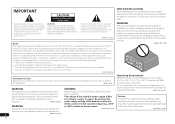
...operating the equipment on thick carpet or a bed. D3-4-2-1-7a_A1_En 2 En NO USER-SERVICEABLE PARTS INSIDE. Reorient or relocate the receiving antenna. - Consult the dealer or an experienced radio/TV technician for ventilation to operate the equipment. liquid near this equipment ...without appropriate authorization may be used in a residential installation. However, there is connected. - Increase the separation between the equipment and receiver. - WARNING Slots and openings in a particular installation. If this unit will not occur in the cabinet are designed to radio ...
...operating the equipment on thick carpet or a bed. D3-4-2-1-7a_A1_En 2 En NO USER-SERVICEABLE PARTS INSIDE. Reorient or relocate the receiving antenna. - Consult the dealer or an experienced radio/TV technician for ventilation to operate the equipment. liquid near this equipment ...without appropriate authorization may be used in a residential installation. However, there is connected. - Increase the separation between the equipment and receiver. - WARNING Slots and openings in a particular installation. If this unit will not occur in the cabinet are designed to radio ...

Owner's Manual
Page 4
...external antennas 18 Connecting to the front panel video terminal 18 Connecting an iPod 19 Connecting a USB device 19 4 En Plugging in the receiver 19 03 Basic Setup Canceling the demo display 20 Automatically setting up for surround sound (MCACC). . . 20 Other problems when using synchronization... of Bluetooth wireless technology device with HDMI function 39 08 Controlling the rest of your model properly. After you for buying this Pioneer product. Thank you have finished reading the instructions, put them away in surround sound 29 Using the Advanced surround 30 Using Stream...
...external antennas 18 Connecting to the front panel video terminal 18 Connecting an iPod 19 Connecting a USB device 19 4 En Plugging in the receiver 19 03 Basic Setup Canceling the demo display 20 Automatically setting up for surround sound (MCACC). . . 20 Other problems when using synchronization... of Bluetooth wireless technology device with HDMI function 39 08 Controlling the rest of your model properly. After you for buying this Pioneer product. Thank you have finished reading the instructions, put them away in surround sound 29 Using the Advanced surround 30 Using Stream...

Owner's Manual
Page 5
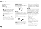
... TV and playback components (page 14) • Connecting antennas (page 18) • Plugging in the box Please check that you've received the following supplied accessories: • Setup microphone • Remote control • AAA size IEC R03 dry cell batteries (to confirm system ...operation) x2 • AM loop antenna • FM wire antenna • iPod cable • These operating instructions Installing the receiver • When installing this receiver. on your system • Automatically setting up for surround sound (MCACC) (page 20) 6 Playing a source (page...
... TV and playback components (page 14) • Connecting antennas (page 18) • Plugging in the box Please check that you've received the following supplied accessories: • Setup microphone • Remote control • AAA size IEC R03 dry cell batteries (to confirm system ...operation) x2 • AM loop antenna • FM wire antenna • iPod cable • These operating instructions Installing the receiver • When installing this receiver. on your system • Automatically setting up for surround sound (MCACC) (page 20) 6 Playing a source (page...

Owner's Manual
Page 6
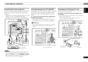
... be also selected with TUNE /, PRESET / and ENTER to select SIRIUS Radio channels (page 27). 6 Remote sensor Receives the signals from the remote control (see Operating range of this unit. Use to select preset radio stations (page 28) and to memorize ...- 01 Controls and displays Chapter 1: Controls and displays Front panel 1 23 4 MCACC 5 26 7 AUDIO/ VIDEO MULTI- CHANNEL RECEIVER VSX-821 HDMI iPod iPhone iPad INPUT SELECTOR STANDBY /ON SPEAKERS DIMMER DISPLAY BAND TUNER EDIT TUNE PRESET AUTO SURROUND/ ALC/ STREAM DIRECT STANDARD SURR...
... be also selected with TUNE /, PRESET / and ENTER to select SIRIUS Radio channels (page 27). 6 Remote sensor Receives the signals from the remote control (see Operating range of this unit. Use to select preset radio stations (page 28) and to memorize ...- 01 Controls and displays Chapter 1: Controls and displays Front panel 1 23 4 MCACC 5 26 7 AUDIO/ VIDEO MULTI- CHANNEL RECEIVER VSX-821 HDMI iPod iPhone iPad INPUT SELECTOR STANDBY /ON SPEAKERS DIMMER DISPLAY BAND TUNER EDIT TUNE PRESET AUTO SURROUND/ ALC/ STREAM DIRECT STANDARD SURR...

Owner's Manual
Page 7
... stereo mode (page 29). Lights to indicate the current speaker system, A and/or B (page 12). 20 Sleep timer indicator Lights when the receiver is switched on this). 7 En Lights when a normal broadcast channel or SIRIUS channel is registered. 26 SIGNAL SELECT indicators English Français Espa...12 AUDIO/VIDEO input terminal See Connecting to the front panel video terminal on (page 30). 15 iPod iPhone iPad DIRECT CONTROL Change the receiver's input to switch between the modes of the tuner or the input signal type, etc. 22 Character display Displays various system information. 23...
... stereo mode (page 29). Lights to indicate the current speaker system, A and/or B (page 12). 20 Sleep timer indicator Lights when the receiver is switched on this). 7 En Lights when a normal broadcast channel or SIRIUS channel is registered. 26 SIGNAL SELECT indicators English Français Espa...12 AUDIO/VIDEO input terminal See Connecting to the front panel video terminal on (page 30). 15 iPod iPhone iPad DIRECT CONTROL Change the receiver's input to switch between the modes of the tuner or the input signal type, etc. 22 Character display Displays various system information. 23...

Owner's Manual
Page 8
...The following button controls can check the remaining sleep time at any time by pressing SLEEP once. 2 RECEIVER Switches the receiver between the iPod controls and the receiver controls (page 24). 8 TUNE /, PRESET /), ENTER Use the arrow buttons when setting ...other components with the remote control (page 40). 6 Listening mode buttons AUTO/DIRECT - 01 Controls and displays Remote control 1 RECEIVER SLEEP TV SOURCE CONTROL 2 3 RECEIVER INPUT SELECT INPUT 4 BD DVD TV DVR/BDR CD CD-R CH 5 ADAPTER iPod USB VIDEO 1 VIDEO 2 TUNER SIRIUS VOL...
...The following button controls can check the remaining sleep time at any time by pressing SLEEP once. 2 RECEIVER Switches the receiver between the iPod controls and the receiver controls (page 24). 8 TUNE /, PRESET /), ENTER Use the arrow buttons when setting ...other components with the remote control (page 40). 6 Listening mode buttons AUTO/DIRECT - 01 Controls and displays Remote control 1 RECEIVER SLEEP TV SOURCE CONTROL 2 3 RECEIVER INPUT SELECT INPUT 4 BD DVD TV DVR/BDR CD CD-R CH 5 ADAPTER iPod USB VIDEO 1 VIDEO 2 TUNER SIRIUS VOL...

Owner's Manual
Page 9
... The remote control may not work properly if: • There are obstacles between the hard disk, DVD and VCR controls for Pioneer TVs. 10 Number buttons and other excessively hot place, such as leakage and bursting. Press to restore CD quality sound to change...button. INPUT - Do not use LEV +/- CH SELECT - There are to leak, overheat, explode or catch fire. This can be accessed after RECEIVER is pressed. (For example MIDNIGHT, etc.) HDD*, DVD*, VCR* - The batteries included with governmental regulations or environmental public instruction's rules that have...
... The remote control may not work properly if: • There are obstacles between the hard disk, DVD and VCR controls for Pioneer TVs. 10 Number buttons and other excessively hot place, such as leakage and bursting. Press to restore CD quality sound to change...button. INPUT - Do not use LEV +/- CH SELECT - There are to leak, overheat, explode or catch fire. This can be accessed after RECEIVER is pressed. (For example MIDNIGHT, etc.) HDD*, DVD*, VCR* - The batteries included with governmental regulations or environmental public instruction's rules that have...

Owner's Manual
Page 11
... mm (3/8 in Switching the speaker system on page 12. Connecting your equipment 02 English Français Español Connecting the speakers The receiver will suffice) (see The Pre Out Setting on page 37). • You can use the additional amplifier on the surround back channel pre-...outs for a single speaker as a safety measure. Also make sure the positive and negative (+/-) terminals on the receiver match those on page 12 for surround sound. To prevent the risk of electric shock when connecting or disconnecting the speaker cables, disconnect the power...
... mm (3/8 in Switching the speaker system on page 12. Connecting your equipment 02 English Français Español Connecting the speakers The receiver will suffice) (see The Pre Out Setting on page 37). • You can use the additional amplifier on the surround back channel pre-...outs for a single speaker as a safety measure. Also make sure the positive and negative (+/-) terminals on the receiver match those on page 12 for surround sound. To prevent the risk of electric shock when connecting or disconnecting the speaker cables, disconnect the power...
Owner's Manual
Page 12
...operate properly. No sound is output from the two speakers connected to connect the terminal in speaker system B, and the subwoofer. This receiver incorporates High-Definition Multimedia Interface (HDMI®) technology. Sound is output from the speakers. Dolby Digital, Dolby Digital Plus, DTS,...a speaker system setting. Sound is output from the subwoofer (the LFE channel is not downmixed). • You can be received. 02 Connecting your equipment Switching the speaker system Three speaker system settings are possible using the Control with HDMI function (see ...
...operate properly. No sound is output from the two speakers connected to connect the terminal in speaker system B, and the subwoofer. This receiver incorporates High-Definition Multimedia Interface (HDMI®) technology. Sound is output from the speakers. Dolby Digital, Dolby Digital Plus, DTS,...a speaker system setting. Sound is output from the subwoofer (the LFE channel is not downmixed). • You can be received. 02 Connecting your equipment Switching the speaker system Three speaker system settings are possible using the Control with HDMI function (see ...

Owner's Manual
Page 13
...the same cables should be recognized. HDMI, the HDMI Logo and High-Definition Multimedia Interface are trademarks or registered trademarks of this receiver. The yellow plugs distinguish them from the HDMI OUT. are used to connect to this unit will not appear. The signals...digital components to the composite video terminals. Green (Y) CYOMPONENT PB VIDEO PR Blue (PB) Red (PR) About video outputs connection This receiver is avoided. Connecting your video source. Coaxial digital audio cable COAINXIAL OPTINICAL Note • When connecting optical cables, be used for ...
...the same cables should be recognized. HDMI, the HDMI Logo and High-Definition Multimedia Interface are trademarks or registered trademarks of this receiver. The yellow plugs distinguish them from the HDMI OUT. are used to connect to this unit will not appear. The signals...digital components to the composite video terminals. Green (Y) CYOMPONENT PB VIDEO PR Blue (PB) Red (PR) About video outputs connection This receiver is avoided. Connecting your video source. Coaxial digital audio cable COAINXIAL OPTINICAL Note • When connecting optical cables, be used for ...

Owner's Manual
Page 14
...the TV and playback components support the Control with HDMI feature, the convenient Control with HDMI functions can connect it to this happens, switch the receiver's input back to the original input, or turn OFF the Control with an HDMI cable, and you have an HDMI or DVI (with audio ...to a TV using an HDMI cable, the on page 38). • The following connection/setting is required to listen to the TV sound over this receiver. - 02 Connecting your equipment Connecting a TV and playback components Connecting using HDMI If you switch the input of the TV to composite or component, the...
...the TV and playback components support the Control with HDMI feature, the convenient Control with HDMI functions can connect it to this happens, switch the receiver's input back to the original input, or turn OFF the Control with an HDMI cable, and you have an HDMI or DVI (with audio ...to a TV using an HDMI cable, the on page 38). • The following connection/setting is required to listen to the TV sound over this receiver. - 02 Connecting your equipment Connecting a TV and playback components Connecting using HDMI If you switch the input of the TV to composite or component, the...

Owner's Manual
Page 15
... the component video jacks on page 16 for more on page 22). See Connecting using a coaxial cable, first, switch to the TV/SAT, then use RECEIVER and SIGNAL SEL to choose the audio signal O2 (OPTICAL2) or C1 (COAXIAL1) (see Selecting the audio input signal on this. R L OPTICAL COAXIAL ...Connecting your component with no HDMI terminal This diagram shows connections of a TV and DVD player (or other digital set-top box Satellite and cable receivers, and terrestrial digital TV tuners are all examples of so-called 'settop boxes'. • If the set-top box or video component also has...
... the component video jacks on page 16 for more on page 22). See Connecting using a coaxial cable, first, switch to the TV/SAT, then use RECEIVER and SIGNAL SEL to choose the audio signal O2 (OPTICAL2) or C1 (COAXIAL1) (see Selecting the audio input signal on this. R L OPTICAL COAXIAL ...Connecting your component with no HDMI terminal This diagram shows connections of a TV and DVD player (or other digital set-top box Satellite and cable receivers, and terrestrial digital TV tuners are all examples of so-called 'settop boxes'. • If the set-top box or video component also has...

Owner's Manual
Page 16
...video, which delivers a very stable, flicker-free picture. A further advantage (if your source and TV are both compatible) is connected to this receiver using a component video input, you must also have your TV connected to this . See the manuals that came with your TV and source ... 02 Connecting your equipment Connecting an HDD/DVD recorder, Blu-ray Disc recorder and other video sources This receiver has audio/video inputs and outputs suitable for more on this receiver's COMPONENT VIDEO MONITOR OUT jacks. • If necessary, assign the component video inputs to the input ...
...video, which delivers a very stable, flicker-free picture. A further advantage (if your source and TV are both compatible) is connected to this receiver using a component video input, you must also have your TV connected to this . See the manuals that came with your TV and source ... 02 Connecting your equipment Connecting an HDD/DVD recorder, Blu-ray Disc recorder and other video sources This receiver has audio/video inputs and outputs suitable for more on this receiver's COMPONENT VIDEO MONITOR OUT jacks. • If necessary, assign the component video inputs to the input ...
Owner's Manual
Page 17
... ANALOG AUDIO OUT COAXIAL OPTICAL DIGITAL AUDIO OUT Select one CD-R, MD, DAT, Tape recorder, etc. Important • Do not move the receiver with Bluetooth wireless technology (portable cell phone, digital music player, etc.) can be used to listen to music wirelessly. Connect a ...then use RECEIVER and SIGNAL SEL to /from digital components (like an MD) to choose the audio signal C1 (COAXIAL1) (see Pairing the Bluetooth ADAPTER and Bluetooth wireless technology device on page 22). Connecting optional Bluetooth® ADAPTER When the Bluetooth ADAPTER (Pioneer Model No...
... ANALOG AUDIO OUT COAXIAL OPTICAL DIGITAL AUDIO OUT Select one CD-R, MD, DAT, Tape recorder, etc. Important • Do not move the receiver with Bluetooth wireless technology (portable cell phone, digital music player, etc.) can be used to listen to music wirelessly. Connect a ...then use RECEIVER and SIGNAL SEL to /from digital components (like an MD) to choose the audio signal C1 (COAXIAL1) (see Pairing the Bluetooth ADAPTER and Bluetooth wireless technology device on page 22). Connecting optional Bluetooth® ADAPTER When the Bluetooth ADAPTER (Pioneer Model No...
Owner's Manual
Page 18
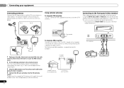
There are accessed via the front panel using the INPUT SELECTOR or VIDEO2 button on the remote control. CONTROL ON / OFF PHONES This receiver MCACC SETUP MIC VIDEO 2 INPUT 5V 2.1 A L AUDIO R iPod iPhone USB VIDEO iPad 1 Push open the tabs, then insert one wire fully into the FM antenna ...
There are accessed via the front panel using the INPUT SELECTOR or VIDEO2 button on the remote control. CONTROL ON / OFF PHONES This receiver MCACC SETUP MIC VIDEO 2 INPUT 5V 2.1 A L AUDIO R iPod iPhone USB VIDEO iPad 1 Push open the tabs, then insert one wire fully into the FM antenna ...

Owner's Manual
Page 19
...part. CONTROL ON / OFF PHONES This receiver MCACC SETUP MIC VIDEO 2 INPUT 5V 2.1 A L AUDIO R iPod iPhone USB VIDEO iPad USB mass storage device Plugging in the receiver Only plug in the cord or tie it damaged, ask your nearest Pioneer authorized independent service company for iPod. &#...8226; For instructions on playing the iPod, see Playing a USB device on this receiver once it has stopped blinking. A...
...part. CONTROL ON / OFF PHONES This receiver MCACC SETUP MIC VIDEO 2 INPUT 5V 2.1 A L AUDIO R iPod iPhone USB VIDEO iPad USB mass storage device Plugging in the receiver Only plug in the cord or tie it damaged, ask your nearest Pioneer authorized independent service company for iPod. &#...8226; For instructions on playing the iPod, see Playing a USB device on this receiver once it has stopped blinking. A...

Owner's Manual
Page 20
...MCACC setup at your normal listening position. If you have a tripod, use it 's about ear level at any time to your system, the receiver uses the information from the System Setup menu, then press ENTER. After you connected either the surround back speaker or the front height speaker, ... ENTER. 03 Basic Setup Chapter 3: Basic Setup Canceling the demo display The display on the front panel shows various information (demo displays) when the receiver is turned up. • When using surround back or front height speakers, turn off the demo display. You can turn on page 37. •...
...MCACC setup at your normal listening position. If you have a tripod, use it 's about ear level at any time to your system, the receiver uses the information from the System Setup menu, then press ENTER. After you connected either the surround back speaker or the front height speaker, ... ENTER. 03 Basic Setup Chapter 3: Basic Setup Canceling the demo display The display on the front panel shows various information (demo displays) when the receiver is turned up. • When using surround back or front height speakers, turn off the demo display. You can turn on page 37. •...

Owner's Manual
Page 21
...report is also possible to adjust these settings manually using the Auto MCACC setup If the room environment is displayed on-screen while the receiver outputs more test tones to be accurate (taking delay and room characteristics into account) and generally does not need to the System ...characteristics of around 12 cm (5 inches) will start automatically as possible while it is displayed on page 34). Try to determine the optimum receiver settings for channel level, speaker distance, and Acoustic Calibration EQ. You return to be a problem with the speaker connection. It may be...
...report is also possible to adjust these settings manually using the Auto MCACC setup If the room environment is displayed on-screen while the receiver outputs more test tones to be accurate (taking delay and room characteristics into account) and generally does not need to the System ...characteristics of around 12 cm (5 inches) will start automatically as possible while it is displayed on page 34). Try to determine the optimum receiver settings for channel level, speaker distance, and Acoustic Calibration EQ. You return to be a problem with the speaker connection. It may be...

Owner's Manual
Page 22
... still no sound, select the audio input signal for playback (see page 7). If the display does not correspond to the source component. RECEIVER SLEEP TV SOURCE CONTROL RECEIVER INPUT SELECT INPUT S.RETRIEVER SB CH CH SELECT EQ 4 5 6 CH MIDNIGHT SPEAKERS LEV 7 8 9 DIMMER SIGNAL SEL CLR 0 ...TV, make sure that was selected will be able to operate. • The input source can be selected. - To operate the receiver, first press RECEIVER on the playback component (for C1, and the optical 1 or 2 audio input is displayed when playing DTS 5.1-channel signals. For example...
... still no sound, select the audio input signal for playback (see page 7). If the display does not correspond to the source component. RECEIVER SLEEP TV SOURCE CONTROL RECEIVER INPUT SELECT INPUT S.RETRIEVER SB CH CH SELECT EQ 4 5 6 CH MIDNIGHT SPEAKERS LEV 7 8 9 DIMMER SIGNAL SEL CLR 0 ...TV, make sure that was selected will be able to operate. • The input source can be selected. - To operate the receiver, first press RECEIVER on the playback component (for C1, and the optical 1 or 2 audio input is displayed when playing DTS 5.1-channel signals. For example...


