Operating Instructions
Page 5
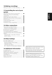
... Systems, Inc. 10 Making recordings Making an audio or a video recording . . . . . 47 11 Controlling the rest of your system Operating other Pioneer components . . . . . 48 Setting the remote to control other components 48 Selecting preset codes directly 49 Erasing all of the remote control presets . ...menu 59 Dynamic Range Control Setup 59 Dual Mono Setup 60 LFE Attenuator Setup 60 SR+ Setup for Pioneer plasma displays . . 60 14 Additional information Troubleshooting 61 Resetting the main unit 63 Switching the speaker impedance 63 Changing the TV format setting 63 Specifications ...
... Systems, Inc. 10 Making recordings Making an audio or a video recording . . . . . 47 11 Controlling the rest of your system Operating other Pioneer components . . . . . 48 Setting the remote to control other components 48 Selecting preset codes directly 49 Erasing all of the remote control presets . ...menu 59 Dynamic Range Control Setup 59 Dual Mono Setup 60 LFE Attenuator Setup 60 SR+ Setup for Pioneer plasma displays . . 60 14 Additional information Troubleshooting 61 Resetting the main unit 63 Switching the speaker impedance 63 Changing the TV format setting 63 Specifications ...
Operating Instructions
Page 34
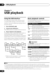
.../MP3/MPEG-4 AAC files (except files with all files are too high for this unit to a personal computer for USB playback. • Pioneer cannot guarantee compatibility (operation and/or bus power) with copy-protection or restricted playback). 2 • Compatible USB devices include external magnetic hard drives... the points below . 1 Press USB (SHIFT+AM). 2 Connect your USB device. USB ERR2 The USB device is incompatible USB ERR3 See Troubleshooting on page 61 for more on this receiver. • With large amounts of the USB USB ERR1 device are played before continuing to folders/...
.../MP3/MPEG-4 AAC files (except files with all files are too high for this unit to a personal computer for USB playback. • Pioneer cannot guarantee compatibility (operation and/or bus power) with copy-protection or restricted playback). 2 • Compatible USB devices include external magnetic hard drives... the points below . 1 Press USB (SHIFT+AM). 2 Connect your USB device. USB ERR2 The USB device is incompatible USB ERR3 See Troubleshooting on page 61 for more on this receiver. • With large amounts of the USB USB ERR1 device are played before continuing to folders/...
Operating Instructions
Page 61
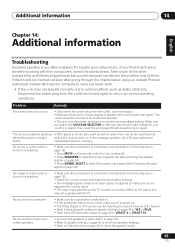
... points below , ask your country or region, then reset the unit (page 63) before switching on . If the message persists, call a Pioneer authorized blinks. Refer to normal operating conditions. No sound from the outlet and insert again to return to the instruction manual supplied with this time...through the checks below . Additional information 14 English Deutsch Français Italiano Nederlands Español Chapter 14: Additional information Troubleshooting Incorrect operations are no loose strands of speaker wire touching the rear panel. independent service company.
... points below , ask your country or region, then reset the unit (page 63) before switching on . If the message persists, call a Pioneer authorized blinks. Refer to normal operating conditions. No sound from the outlet and insert again to return to the instruction manual supplied with this time...through the checks below . Additional information 14 English Deutsch Français Italiano Nederlands Español Chapter 14: Additional information Troubleshooting Incorrect operations are no loose strands of speaker wire touching the rear panel. independent service company.
Service Manual
Page 131
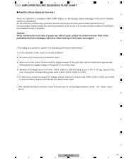
... there is the possibility that each channel of power pack IC600, IC601, IC602 and IC603 to the troubleshooting of fan motor is in normal condition? ↓ 2) Are there any Fuses and IC protectors open / short) D E F VSX-816-K 131 5 6 7 8 B • According to (VL-0.7V). If not (eg, equal to VH), then change the corresponding...
... there is the possibility that each channel of power pack IC600, IC601, IC602 and IC603 to the troubleshooting of fan motor is in normal condition? ↓ 2) Are there any Fuses and IC protectors open / short) D E F VSX-816-K 131 5 6 7 8 B • According to (VL-0.7V). If not (eg, equal to VH), then change the corresponding...
Service Manual
Page 133
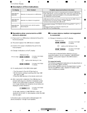
USB ERROR2 USB ERR2 Detection of Troubleshooting. USB ERR3 microcomputer • Defective connection (connectors) inside this unit • See STEP 3 of a medium not supported A USB device that this unit does not support (... will not start playback, press the USB play key is pressed while the error indication is displayed, power supply to the USB module is restored. E F VSX-816-K 133 5 6 7 8 USB ERR1 In a case of an 8-digit FL display (5) To supply power to the USB module again: • Turn the power to the unit...
USB ERROR2 USB ERR2 Detection of Troubleshooting. USB ERR3 microcomputer • Defective connection (connectors) inside this unit • See STEP 3 of a medium not supported A USB device that this unit does not support (... will not start playback, press the USB play key is pressed while the error indication is displayed, power supply to the USB module is restored. E F VSX-816-K 133 5 6 7 8 USB ERR1 In a case of an 8-digit FL display (5) To supply power to the USB module again: • Turn the power to the unit...

Service Manual
Page 134
... IC703. Yes No Check the parts and patterns in the path. Yes No Check the parts and patterns in the path. Yes Replace IC702. A F 134 VSX-816-K 1 2 3 4 Yes To STEP 2 No Insert the connectors securely. Yes 3 IC951 (pin 14) 3-5 Converter D 4 Is the voltage 5 V ?... the path between them . 7 IC762 (pins 37, 47) FLASH ROM Is the voltage 3.3 V ? The output and GND may be short-circuited. 1 2 7.3.4.3 Troubleshooting Step 1: Connectors A CN701, CN702 Are the connectors securely inserted ? No Check the patterns in the path. 3 4 6 IC703 (pin 1), IC702 (pin 7) 3.3 ...
... IC703. Yes No Check the parts and patterns in the path. Yes No Check the parts and patterns in the path. Yes Replace IC702. A F 134 VSX-816-K 1 2 3 4 Yes To STEP 2 No Insert the connectors securely. Yes 3 IC951 (pin 14) 3-5 Converter D 4 Is the voltage 5 V ?... the path between them . 7 IC762 (pins 37, 47) FLASH ROM Is the voltage 3.3 V ? The output and GND may be short-circuited. 1 2 7.3.4.3 Troubleshooting Step 1: Connectors A CN701, CN702 Are the connectors securely inserted ? No Check the patterns in the path. 3 4 6 IC703 (pin 1), IC702 (pin 7) 3.3 ...


