Service Manual
Page 1
Type Model PL-990 Power Requirement The voltage can be converted by the following method. 0 PIONEER. The Art of Entertainment Service Manual 60) STEREO TURNTABLE PL-990 ORDER NO. PCB PARTS LIST 10 5. SPECIFICATIONS 12 PIONEER ELECTRONIC CORPORATION 4-1, Meguro 1-Chome, Meguro-ku, Tokyo 153, Japan PIONEER ELECTRONICS SERVICE, INC. LTD. 501 Orchard Road, #10-00 Lane Crawford Place, Singapore 0923 © PIONEER ELECTRONIC CORPORATION 1996 T-FFB JUNE...
Type Model PL-990 Power Requirement The voltage can be converted by the following method. 0 PIONEER. The Art of Entertainment Service Manual 60) STEREO TURNTABLE PL-990 ORDER NO. PCB PARTS LIST 10 5. SPECIFICATIONS 12 PIONEER ELECTRONIC CORPORATION 4-1, Meguro 1-Chome, Meguro-ku, Tokyo 153, Japan PIONEER ELECTRONICS SERVICE, INC. LTD. 501 Orchard Road, #10-00 Lane Crawford Place, Singapore 0923 © PIONEER ELECTRONIC CORPORATION 1996 T-FFB JUNE...
Service Manual
Page 2
... harm (California Health & Safety Code, Section 25249.5). For the latest information, always consult the current PIONEER Service Manual. PL-990 1. If you should be obtained at a nominal charge from visual inspection nor the protection afforded by using replacement components rated for the continued protection of , PIONEER Service Manual may void the warranty. Device under review and new instructions are often not evident from PIONEER. 2 These are issued...
... harm (California Health & Safety Code, Section 25249.5). For the latest information, always consult the current PIONEER Service Manual. PL-990 1. If you should be obtained at a nominal charge from visual inspection nor the protection afforded by using replacement components rated for the continued protection of , PIONEER Service Manual may void the warranty. Device under review and new instructions are often not evident from PIONEER. 2 These are issued...
Service Manual
Page 3
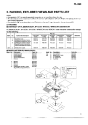
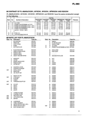
... 10 OPERATING INSTRUCTIONS (English/French/Spanish/Chinese) PZH1020 PZH1022 PZH1023 PZH1024 PZR1002 elo 13 Except RDXCN1 type c44 14 5 6 11 8 10 3 c, 1:t.. . 9 15 0 0 0- Therefore, when replacing, be sure to use parts of identical designation. • Parts marked by "NSP" are generally unavailable because they may be unavailable. 2.1 PACKING ■ CONTRAST OF PL-990/KUCXCN1, WYXCN1, WVXCN1, WPWXCN1 AND RDXCN1 PL-990...
... 10 OPERATING INSTRUCTIONS (English/French/Spanish/Chinese) PZH1020 PZH1022 PZH1023 PZH1024 PZR1002 elo 13 Except RDXCN1 type c44 14 5 6 11 8 10 3 c, 1:t.. . 9 15 0 0 0- Therefore, when replacing, be sure to use parts of identical designation. • Parts marked by "NSP" are generally unavailable because they may be unavailable. 2.1 PACKING ■ CONTRAST OF PL-990/KUCXCN1, WYXCN1, WVXCN1, WPWXCN1 AND RDXCN1 PL-990...
Service Manual
Page 4
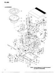
PL-990 2.2 EXTERIOR 83 CD CD O 40 0 O 23 85 18 141 100 , 54 139 82 33 93 34 ti 8 79 91 98 22 109 10 1 8 102 137 ... 61 6 101 24 32 27 89 111 O eo 89 lro RDXCN1 type only 47 ct) 13 62 39 52 59 95 99 28 74-' 51 FUSE(3A) 43 40 87 29 97 80 89 68 62 136 84 55 60 57 47 57 84 60 NOTE : Screws adjacent to V mark on...
PL-990 2.2 EXTERIOR 83 CD CD O 40 0 O 23 85 18 141 100 , 54 139 82 33 93 34 ti 8 79 91 98 22 109 10 1 8 102 137 ... 61 6 101 24 32 27 89 111 O eo 89 lro RDXCN1 type only 47 ct) 13 62 39 52 59 95 99 28 74-' 51 FUSE(3A) 43 40 87 29 97 80 89 68 62 136 84 55 60 57 47 57 84 60 NOTE : Screws adjacent to V mark on...
Service Manual
Page 5
... OF PL-990/KUCXCN1, WYXCN1, WVXCN1, WPWXCN1 AND RDXCN1 PL-990/KUCXCN1, WYXCN1, WVXCN1, WPWXCN1 and RDXCN1 have the same construction except for the following: Part No. Description Parts No. 41 SPRING PZB1006 42 P.C.BOARD ASSY PZX 1027 43 SIGNAL WIRE A 44 AC CORD PZKI006 PZKI007 45 POWER TRANSFORMER (ACI20V) PZT1001 6 PLAY,STOP KNOB 7 SPEED,CUEING KNOB 8 PENDULUM(L) 9 PENDULUM(M) 10 SELECT RECORD...
... OF PL-990/KUCXCN1, WYXCN1, WVXCN1, WPWXCN1 AND RDXCN1 PL-990/KUCXCN1, WYXCN1, WVXCN1, WPWXCN1 and RDXCN1 have the same construction except for the following: Part No. Description Parts No. 41 SPRING PZB1006 42 P.C.BOARD ASSY PZX 1027 43 SIGNAL WIRE A 44 AC CORD PZKI006 PZKI007 45 POWER TRANSFORMER (ACI20V) PZT1001 6 PLAY,STOP KNOB 7 SPEED,CUEING KNOB 8 PENDULUM(L) 9 PENDULUM(M) 10 SELECT RECORD...
Service Manual
Page 6
... NSP 112 HEADSHELL NSP 113 TONEARM SET NSP 114 ROTARY SHAFT ASSY NSP 115 PIN PZN1075 116 STYLUS COVER 117 STYLUS NSP 118 SCREW NSP 119 GROUND SHEET NSP 120 WIRE PZPI002 PZPI004 NSP 121 SCREW NSP 122 SPRING 123 NSP 124 SHIELD WIRE (WHITE) NSP 125 SHIELD WIRE (RED) 126 PLASTIC KNOB PZN1089 127... 138 SCREW 139 WASHER 140 MOTOR ASSY 141 T/T SHAFT ASSY 142 GEAR ASSY 143 TONEARM ASSY Parts No. PL-990 Mark No. Description 81 SPRING 82 RUBBER FOR DUSTCOVER 83 PLATTER MAT 84 RUBBER FOOT 85 BELT Parts No. RING WASHER(5mm) PZN1065 PZN1066 PZB1038 PZB1039 PZB1040 NSP 91 CS WASHER(3mm) 92 WASHER...
... NSP 112 HEADSHELL NSP 113 TONEARM SET NSP 114 ROTARY SHAFT ASSY NSP 115 PIN PZN1075 116 STYLUS COVER 117 STYLUS NSP 118 SCREW NSP 119 GROUND SHEET NSP 120 WIRE PZPI002 PZPI004 NSP 121 SCREW NSP 122 SPRING 123 NSP 124 SHIELD WIRE (WHITE) NSP 125 SHIELD WIRE (RED) 126 PLASTIC KNOB PZN1089 127... 138 SCREW 139 WASHER 140 MOTOR ASSY 141 T/T SHAFT ASSY 142 GEAR ASSY 143 TONEARM ASSY Parts No. PL-990 Mark No. Description 81 SPRING 82 RUBBER FOR DUSTCOVER 83 PLATTER MAT 84 RUBBER FOOT 85 BELT Parts No. RING WASHER(5mm) PZN1065 PZN1066 PZB1038 PZB1039 PZB1040 NSP 91 CS WASHER(3mm) 92 WASHER...
Service Manual
Page 7
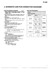
... some component parts indicates the im- Therefore, when re- Part numbers in PCB diagrams match those in Schematic Diagrams Part Name B C EB C E (o o o) B C E Transistor e(o o o) BCE (a a o) DG S B C EB C E Transistor with resistor DG SDG S Field effect transistor (a a oSSo a 6)1 0 0 0 Hil- Rated power: 1/4W, 1/6W, 1/8W, 1/10W unless otherwise noted. Rated voltage: 50V except for improve. placing, be changed for electrolytic capacitors. 5. When ordering service parts, be...
... some component parts indicates the im- Therefore, when re- Part numbers in PCB diagrams match those in Schematic Diagrams Part Name B C EB C E (o o o) B C E Transistor e(o o o) BCE (a a o) DG S B C EB C E Transistor with resistor DG SDG S Field effect transistor (a a oSSo a 6)1 0 0 0 Hil- Rated power: 1/4W, 1/6W, 1/8W, 1/10W unless otherwise noted. Rated voltage: 50V except for improve. placing, be changed for electrolytic capacitors. 5. When ordering service parts, be...

Service Manual
Page 8
...8226; O A POWER SW3 PZS1001 3 TRANSFORMER • O KUCXCN1 .PZT1001 SW2 PZS1001 WYXCN1,WVXCN1 PZT1002 WPWXCN1 PZT1004 ISW sw RED YEL AC C2 BLK: YEL AC 0.022 RED PLAY SW N N 0 0 O o 0 z z Y B 0Z 0N 00TsN z Z 727 BLK I RED SPEED MOTOR ASSY IPZX1025 ADJUST VR _ AV...,±0: 109 SW1 10K 2.2K A WHT P2S1002 33rpm B YEL 45r pm SW1 SPEED SELECT SW P.C.BOARD ASSY PZX1027 ...
...8226; O A POWER SW3 PZS1001 3 TRANSFORMER • O KUCXCN1 .PZT1001 SW2 PZS1001 WYXCN1,WVXCN1 PZT1002 WPWXCN1 PZT1004 ISW sw RED YEL AC C2 BLK: YEL AC 0.022 RED PLAY SW N N 0 0 O o 0 z z Y B 0Z 0N 00TsN z Z 727 BLK I RED SPEED MOTOR ASSY IPZX1025 ADJUST VR _ AV...,±0: 109 SW1 10K 2.2K A WHT P2S1002 33rpm B YEL 45r pm SW1 SPEED SELECT SW P.C.BOARD ASSY PZX1027 ...

Service Manual
Page 9
.... INI=1- 01 - Ca - D2 v - {=10-- PL-990 TO CARTRIDGE 014 EQ P.C.BOARD ASSY EQ AMP C202 r•o R203 •LY 194HB (-0 ,A0 2 rc?. D4 V TO POWER TRANSFORMER AC IN • This diagram is viewed from the mounted parts side. • The parts mounted on this PCB include all necessary parts for respective destinations, be sure to check with the schematic diagram. 9
.... INI=1- 01 - Ca - D2 v - {=10-- PL-990 TO CARTRIDGE 014 EQ P.C.BOARD ASSY EQ AMP C202 r•o R203 •LY 194HB (-0 ,A0 2 rc?. D4 V TO POWER TRANSFORMER AC IN • This diagram is viewed from the mounted parts side. • The parts mounted on this PCB include all necessary parts for respective destinations, be sure to check with the schematic diagram. 9
Service Manual
Page 10
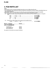
PL-990 4. P.C.BOARD ASSY LED P.C.BOARD ASSY EQ P.C.BOARD ASSY PZX1027 PZX1028 PZX1029 The components of identical designation. • Parts marked by "0" are not selected for maintenance. 1O Therefore, when replacing, be sure to use parts of each assembly are not always kept ...first convert resistance values into codeform as in our Master Spare Parts List. • The Lt. Description LIST OF ASSEMBLIES Parts No. markfound on some component parts indicates the importance of the safetyfactor of the part. PCB PARTS LIST NOTES: • Parts marked by J = 5%, and K = ...
PL-990 4. P.C.BOARD ASSY LED P.C.BOARD ASSY EQ P.C.BOARD ASSY PZX1027 PZX1028 PZX1029 The components of identical designation. • Parts marked by "0" are not selected for maintenance. 1O Therefore, when replacing, be sure to use parts of each assembly are not always kept ...first convert resistance values into codeform as in our Master Spare Parts List. • The Lt. Description LIST OF ASSEMBLIES Parts No. markfound on some component parts indicates the importance of the safetyfactor of the part. PCB PARTS LIST NOTES: • Parts marked by J = 5%, and K = ...
Service Manual
Page 11
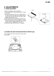
... again. 5. TOP VIEW PL-990 BOTTOM VIEW 0 00 5.2 CHANGE THE LINE VOLTAGE SELECTOR (for 33-1/3rpm of test record. (3) Insert your screwdriver into the H hole (45rpm) of the motor, adjust the VR to play the track for 45rpm of the test record. (5) Insert your screwdriver into the L hole (33-1/3rpm) of the mo- ADJUSTMENTS 5.1 SPEED ADJUSTMENT (1) Press the Cueing button to the...
... again. 5. TOP VIEW PL-990 BOTTOM VIEW 0 00 5.2 CHANGE THE LINE VOLTAGE SELECTOR (for 33-1/3rpm of test record. (3) Insert your screwdriver into the H hole (45rpm) of the motor, adjust the VR to play the track for 45rpm of the test record. (5) Insert your screwdriver into the L hole (33-1/3rpm) of the mo- ADJUSTMENTS 5.1 SPEED ADJUSTMENT (1) Press the Cueing button to the...
Service Manual
Page 12
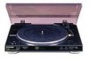
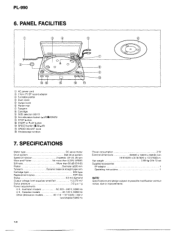
... 1 Operating instructions 1 NOTE: Specifications and design subject to possible modification without notice, due to improvements. 12 PANEL FACILITIES 0 F 11 • I= 0 6 CD O (=I 13 CD • AC power cord © 17cm IT) EP record adaptor C) Turntable platter 0 Dust cover C) Output cord 0 Platter mat (r) Tonearm ® Cartridge C) SIZE selector (30/17) § Arm-elevation button (...UP/IDOWN) # STOP button # START or PLAY button • SPEED button...
... 1 Operating instructions 1 NOTE: Specifications and design subject to possible modification without notice, due to improvements. 12 PANEL FACILITIES 0 F 11 • I= 0 6 CD O (=I 13 CD • AC power cord © 17cm IT) EP record adaptor C) Turntable platter 0 Dust cover C) Output cord 0 Platter mat (r) Tonearm ® Cartridge C) SIZE selector (30/17) § Arm-elevation button (...UP/IDOWN) # STOP button # START or PLAY button • SPEED button...


