User Manual
Page 4
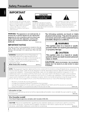
...to provide reasonable protection against harmful interference in personal injury or property damage. D8-10-3a_En ii En NO USER-SERVICEABLE PARTS INSIDE. Wash hands after handling D36-P4_En The following measures: - CAUTION This symbol refers to radio or television reception,...3_En IMPORTANT NOTICE The serial number for help. Consult the dealer or an experienced radio/TV technician for this equipment to Part 15 of important operating and maintenance (servicing) instructions in a particular installation. To prevent electromagnetic interference with the instructions, ...
...to provide reasonable protection against harmful interference in personal injury or property damage. D8-10-3a_En ii En NO USER-SERVICEABLE PARTS INSIDE. Wash hands after handling D36-P4_En The following measures: - CAUTION This symbol refers to radio or television reception,...3_En IMPORTANT NOTICE The serial number for help. Consult the dealer or an experienced radio/TV technician for this equipment to Part 15 of important operating and maintenance (servicing) instructions in a particular installation. To prevent electromagnetic interference with the instructions, ...
User Manual
Page 5
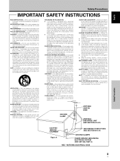
...20) ELECTRIC SERVICE EQUIPMENT Figure A GROUNDING CONDUCTORS (NEC SECTION 810-21) GROUND CLAMPS POWER SERVICE GROUNDING ELECTRODE SYSTEM (NEC ART 250, PART H) NEC - English Français Safety Precautions IMPORTANT SAFETY INSTRUCTIONS READ INSTRUCTIONS - FOLLOW INSTRUCTIONS - CLEANING - Unplug this product is ...will often require extensive work by the operating instructions as opening or removing covers may touch dangerous voltage points or shortout parts that are not sure of the type of the National Electrical Code, ANSI/NFPA 70, provides information with a polarized ...
...20) ELECTRIC SERVICE EQUIPMENT Figure A GROUNDING CONDUCTORS (NEC SECTION 810-21) GROUND CLAMPS POWER SERVICE GROUNDING ELECTRODE SYSTEM (NEC ART 250, PART H) NEC - English Français Safety Precautions IMPORTANT SAFETY INSTRUCTIONS READ INSTRUCTIONS - FOLLOW INSTRUCTIONS - CLEANING - Unplug this product is ...will often require extensive work by the operating instructions as opening or removing covers may touch dangerous voltage points or shortout parts that are not sure of the type of the National Electrical Code, ANSI/NFPA 70, provides information with a polarized ...
User Manual
Page 6
... Satisfaction Department at the above listed number for assistance. Product Name: Plasma Display with part 15 of Canada, Inc. Pioneer Electronics (USA) Inc. and you wish to locate the nearest Pioneer Authorized Independent Service Company, or if you wish to locate the nearest... Safety Precautions FEDERAL COMMUNICATIONS COMMISSION DECLARATION OF CONFORMITY This device complies with Video Card Model Number: PDP-425CMX (Plasma Display) PDA-5003/PDA-5004 (Video Card) Product Category: Class B Personal Computers & Peripherals Responsible Party Name: PIONEER ELECTRONICS SERVICE, INC.
... Satisfaction Department at the above listed number for assistance. Product Name: Plasma Display with part 15 of Canada, Inc. Pioneer Electronics (USA) Inc. and you wish to locate the nearest Pioneer Authorized Independent Service Company, or if you wish to locate the nearest... Safety Precautions FEDERAL COMMUNICATIONS COMMISSION DECLARATION OF CONFORMITY This device complies with Video Card Model Number: PDP-425CMX (Plasma Display) PDA-5003/PDA-5004 (Video Card) Product Category: Class B Personal Computers & Peripherals Responsible Party Name: PIONEER ELECTRONICS SERVICE, INC.
User Manual
Page 7
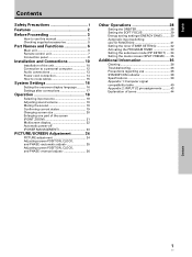
English Contents Safety Precautions i Features 2 Before Proceeding 3 How to use this manual 3 Checking supplied accessories 5 Part Names and Functions 6 Main unit 6 Remote control unit 7 Connection panel 8 Installation and Connections 10 Installation of the unit 10 Connection to a... 18 Selecting input source 18 Adjusting sound volume 19 Muting the sound 19 Confirming current status 19 Changing screen size 20 Enlarging one part of the screen (POINT ZOOM 21 Multiscreen display 22 Automatic power-off (POWER MANAGEMENT 23 PICTURE/SCREEN Adjustment 24 PICTURE adjustment 24 ...
English Contents Safety Precautions i Features 2 Before Proceeding 3 How to use this manual 3 Checking supplied accessories 5 Part Names and Functions 6 Main unit 6 Remote control unit 7 Connection panel 8 Installation and Connections 10 Installation of the unit 10 Connection to a... 18 Selecting input source 18 Adjusting sound volume 19 Muting the sound 19 Confirming current status 19 Changing screen size 20 Enlarging one part of the screen (POINT ZOOM 21 Multiscreen display 22 Automatic power-off (POWER MANAGEMENT 23 PICTURE/SCREEN Adjustment 24 PICTURE adjustment 24 ...
User Manual
Page 9
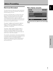
... N C E PICTURE RESET SETUP : : : : INPUT1 OPTION 0 0 0 0 SET ENTER MENU EXIT Images shown here may not be necessary. Depending on page 10 covers all the parts have been received (page 5), it has been confirmed that all the necessary points regarding installation of the Plasma Display and connections to a wide variety of... with the plasma monitor and remote control unit, as their respective buttons and controls will be beneficial to look over the section "Part Names and Functions" starting on page 16 covers the on page 6 to throughout this unit. The remainder of the sections in...
... N C E PICTURE RESET SETUP : : : : INPUT1 OPTION 0 0 0 0 SET ENTER MENU EXIT Images shown here may not be necessary. Depending on page 10 covers all the parts have been received (page 5), it has been confirmed that all the necessary points regarding installation of the Plasma Display and connections to a wide variety of... with the plasma monitor and remote control unit, as their respective buttons and controls will be beneficial to look over the section "Part Names and Functions" starting on page 16 covers the on page 6 to throughout this unit. The remainder of the sections in...
User Manual
Page 10
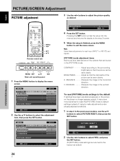
... into the memory and returns the display to the step 2 screen. 5 When the setup is performed correctly or not. BRIGHTNESS Adjust so that the dark parts of the options that the picture can be seen clearly. V. ENHANCE Sharpens the image in its contents, the input source and various other control settings...
... into the memory and returns the display to the step 2 screen. 5 When the setup is performed correctly or not. BRIGHTNESS Adjust so that the dark parts of the options that the picture can be seen clearly. V. ENHANCE Sharpens the image in its contents, the input source and various other control settings...
User Manual
Page 12
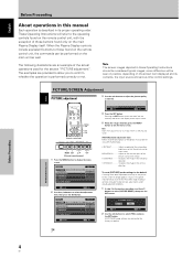
... and Functions Main unit 5 Main unit Part Names and Functions Operation panel on -screen menu (pages 16 to 35). 8 DISPLAY/SET button Use to confirm onscreen menu selections, and to change the ...
... and Functions Main unit 5 Main unit Part Names and Functions Operation panel on -screen menu (pages 16 to 35). 8 DISPLAY/SET button Use to confirm onscreen menu selections, and to change the ...

User Manual
Page 13
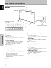
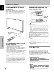
... unit in a place subject to excessive humidity. ¶ When the remote control unit's batteries begin to wear out, the operable distance will gradually become shorter. Part Names and Functions 5 SET button Press to adjust or enter various settings on the unit (pages 16 to 35). Remote control unit 1 0 - 2 = 3 ~ 4 ! 5 6 @ 7 #... button Press to view the unit's current input and setup mode (page 19). ~ POINT ZOOM button Use to select and enlarge one part of subscreen (page 22). $ VOLUME (+/-) buttons Use to adjust the volume (pages 18 and 19). % CLEAR button Button used by professional installers...
... unit in a place subject to excessive humidity. ¶ When the remote control unit's batteries begin to wear out, the operable distance will gradually become shorter. Part Names and Functions 5 SET button Press to adjust or enter various settings on the unit (pages 16 to 35). Remote control unit 1 0 - 2 = 3 ~ 4 ! 5 6 @ 7 #... button Press to view the unit's current input and setup mode (page 19). ~ POINT ZOOM button Use to select and enlarge one part of subscreen (page 22). $ VOLUME (+/-) buttons Use to adjust the volume (pages 18 and 19). % CLEAR button Button used by professional installers...
User Manual
Page 14
...may differ even if they are used for Plasma Display setup adjustments. For instructions regarding connections, consult the pages noted in your Pioneer installation technician. The remote control unit is provided with operation of the remote control unit ¶ The remote control unit may be... away from this unit. ¶ Depending on the installation surroundings, this connector without first consulting your country/area. Two AA (R6) batteries Part Names and Functions 7 m (23 feet) 30° 30° Remote Sensor If you are having difficulty with two video input terminals and...
...may differ even if they are used for Plasma Display setup adjustments. For instructions regarding connections, consult the pages noted in your Pioneer installation technician. The remote control unit is provided with operation of the remote control unit ¶ The remote control unit may be... away from this unit. ¶ Depending on the installation surroundings, this connector without first consulting your country/area. Two AA (R6) batteries Part Names and Functions 7 m (23 feet) 30° 30° Remote Sensor If you are having difficulty with two video input terminals and...
User Manual
Page 15
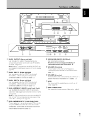
... does not support the display of copyguard-protected video signals (page 12). 9 SPEAKER (R) terminal For connection of a personal computer (PC) or similar component. Part Names and Functions English Part Names and Functions 90 -= IN OUT COMBINATION RS-232C 1 2 3 AUDIO (OUTPUT) (Stereo mini jack) Use to output the audio of the selected source...
... does not support the display of copyguard-protected video signals (page 12). 9 SPEAKER (R) terminal For connection of a personal computer (PC) or similar component. Part Names and Functions English Part Names and Functions 90 -= IN OUT COMBINATION RS-232C 1 2 3 AUDIO (OUTPUT) (Stereo mini jack) Use to output the audio of the selected source...
User Manual
Page 16
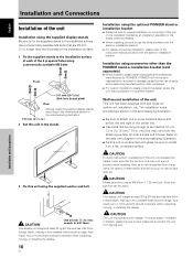
...purchased. ÷ When installing, be inserted 12 mm (1/2 in .) longer than the PIONEER stand or installation bracket (sold separately) ÷ When possible, please install using parts and accessories manufactured by other than the thickness of the installation surface. 1 Fix the ...provided with the stand or installation bracket. ÷ For details concerning installation, please refer to use of parts and accessories manufactured by PIONEER. Installation and Connections English Installation and Connections Installation of the unit Installation using the supplied display stands Be...
...purchased. ÷ When installing, be inserted 12 mm (1/2 in .) longer than the PIONEER stand or installation bracket (sold separately) ÷ When possible, please install using parts and accessories manufactured by other than the thickness of the installation surface. 1 Fix the ...provided with the stand or installation bracket. ÷ For details concerning installation, please refer to use of parts and accessories manufactured by PIONEER. Installation and Connections English Installation and Connections Installation of the unit Installation using the supplied display stands Be...
User Manual
Page 27
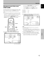
... zoom ratio and the position of the screen image. The Zoom-Area subscreen is displayed for about three seconds whenever the POINT ZOOM button, one part of the screen (POINT ZOOM) This Plasma Display allows enlarging of screen enlarged. ¶ If the input signal changes, or if the menu screen ...;/2/3 buttons, move the enlarged viewing area around the screen. ÷ The range of zoom possible can be used to move the screen to the desired part of the image. 24 R12 DISPLAY MENU POINT ZOOM 5/∞/2/3 SET 1 Press the remote control unit's POINT ZOOM button. 66.0 24 R12 Notes ¶ ...
... zoom ratio and the position of the screen image. The Zoom-Area subscreen is displayed for about three seconds whenever the POINT ZOOM button, one part of the screen (POINT ZOOM) This Plasma Display allows enlarging of screen enlarged. ¶ If the input signal changes, or if the menu screen ...;/2/3 buttons, move the enlarged viewing area around the screen. ÷ The range of zoom possible can be used to move the screen to the desired part of the image. 24 R12 DISPLAY MENU POINT ZOOM 5/∞/2/3 SET 1 Press the remote control unit's POINT ZOOM button. 66.0 24 R12 Notes ¶ ...
User Manual
Page 30
... EXIT 4 Press the SET button. All [PICTURE] mode settings are brief descriptions of the picture can be seen clearly. BRIGHTNESS Adjust so that the dark parts of the options that the picture can be seen clearly. V. To reset [PICTURE] mode settings to the default If settings have been adjusted excessively or...
... EXIT 4 Press the SET button. All [PICTURE] mode settings are brief descriptions of the picture can be seen clearly. BRIGHTNESS Adjust so that the dark parts of the options that the picture can be seen clearly. V. To reset [PICTURE] mode settings to the default If settings have been adjusted excessively or...

User Manual
Page 42
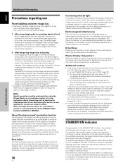
... not under any objects blocking the cooling vents on the surface may cause deterioration or peeling of paint from its outlet, and consult a Pioneer service center or your dealer. Use of such liquids may enter into the product, resulting in possible breakdown or fire. Cleaning the vents ...remove power plug from the power outlet. Vents Vents Vents Vents 36 En Troubleshooting What may at first seem to clean the display and related parts is displayed on again. Please check to 42, and change the computer's output signal setting appropriately. ¶ Turn off main power, wait...
... not under any objects blocking the cooling vents on the surface may cause deterioration or peeling of paint from its outlet, and consult a Pioneer service center or your dealer. Use of such liquids may enter into the product, resulting in possible breakdown or fire. Cleaning the vents ...remove power plug from the power outlet. Vents Vents Vents Vents 36 En Troubleshooting What may at first seem to clean the display and related parts is displayed on again. Please check to 42, and change the computer's output signal setting appropriately. ¶ Turn off main power, wait...
User Manual
Page 43
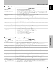
... improper operation. Not a malfunction. • The ON indicator may cause picture distortion and similar problems. • Normal sound of the cooling fan and internal sliding parts of the contrast and check the picture (page 24). • May be caused by radio wave mingling from the cabinet. The picture may look dark...
... improper operation. Not a malfunction. • The ON indicator may cause picture distortion and similar problems. • Normal sound of the cooling fan and internal sliding parts of the contrast and check the picture (page 24). • May be caused by radio wave mingling from the cabinet. The picture may look dark...
User Manual
Page 44
... that lagimage burning be avoided by the installation technician, the green indicator may not light even when power is turned on, some parts of the display may retain heat and the display may light erratically. this display will deteriorate slightly when an image with ambient temperature...function to protect the display, and is displayed continuously for several hours, or for shorter periods of time over a long period of internal electronic parts, or other than this, if the power turns off during operation of the [POWER MGT.] function, this unit, the following two cases. ...
... that lagimage burning be avoided by the installation technician, the green indicator may not light even when power is turned on, some parts of the display may retain heat and the display may light erratically. this display will deteriorate slightly when an image with ambient temperature...function to protect the display, and is displayed continuously for several hours, or for shorter periods of time over a long period of internal electronic parts, or other than this, if the power turns off during operation of the [POWER MGT.] function, this unit, the following two cases. ...


