User Manual
Page 5
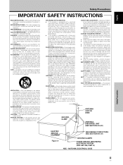
... be mounted to a wall or ceiling only as an improper adjustment of power supply to . CART - POWER LINES - Adjust only those controls that produce heat. POWER SOURCES - If you to dangerous voltage or other ), it from the wall outlet before the product is connected to the product, be walked on the product and in the cabinet are unable to be sure the antenna or cable...
... be mounted to a wall or ceiling only as an improper adjustment of power supply to . CART - POWER LINES - Adjust only those controls that produce heat. POWER SOURCES - If you to dangerous voltage or other ), it from the wall outlet before the product is connected to the product, be walked on the product and in the cabinet are unable to be sure the antenna or cable...
User Manual
Page 7
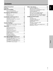
... use this manual 3 Checking supplied accessories 5 Part Names and Functions 6 Main unit 6 Remote control unit 7 Connection panel 8 Installation and Connections 10 Installation of the unit 10 Connection to a personal computer 12 Audio connections 13 Power cord connection 14 How to route cables 15 System Settings 16 Setting the onscreen display language 16 Settings after connections 17 Operation 18 Selecting input source 18 Adjusting sound volume 19 Muting the sound 19 Confirming current status 19 Changing screen size 20 Enlarging one part of the screen...
... use this manual 3 Checking supplied accessories 5 Part Names and Functions 6 Main unit 6 Remote control unit 7 Connection panel 8 Installation and Connections 10 Installation of the unit 10 Connection to a personal computer 12 Audio connections 13 Power cord connection 14 How to route cables 15 System Settings 16 Setting the onscreen display language 16 Settings after connections 17 Operation 18 Selecting input source 18 Adjusting sound volume 19 Muting the sound 19 Confirming current status 19 Changing screen size 20 Enlarging one part of the screen...
User Manual
Page 8
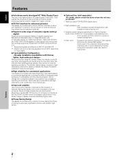
... purchased.) 1 Table top stand: PDP-425CMX display stand. 2 Wall installation unit: Wall installation bracket designed as a wall interface for securing the unit. 3 Speaker system designed specifically for Plasma Displays (width: 9 cm (3-9/16 in.)): 2-way speaker units featuring 5 cm (2 in.) tweeter and 8 cm (3-3/16 in.) woofer in vertical arrangement. 4 Video card: Expansion card allows viewing of possible installation locations and styles. ¶ High reliability for the connection of external devices, thus enhancing its expansion potential. ¶ Supports wide...
... purchased.) 1 Table top stand: PDP-425CMX display stand. 2 Wall installation unit: Wall installation bracket designed as a wall interface for securing the unit. 3 Speaker system designed specifically for Plasma Displays (width: 9 cm (3-9/16 in.)): 2-way speaker units featuring 5 cm (2 in.) tweeter and 8 cm (3-3/16 in.) woofer in vertical arrangement. 4 Video card: Expansion card allows viewing of possible installation locations and styles. ¶ High reliability for the connection of external devices, thus enhancing its expansion potential. ¶ Supports wide...
User Manual
Page 12
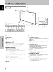
... used to indicate error messages (page 38). 5 Handles Operation panel on the main unit 6 STANDBY/ON button ( ) Press to put the display in standby mode: The indicator lights red (page 18). When flashing, the indicator is in operation or standby mode (page 18). 7 MENU button Press to open and close the on the main unit STANDBY/ON 6 DISPLAY MENU / SET 78 INPUT SCREEN SIZE - VOL + 90 - 1 STANDBY ON 2 34 Main unit 1 Display stand 2 Remote control sensor Point the remote control...
... used to indicate error messages (page 38). 5 Handles Operation panel on the main unit 6 STANDBY/ON button ( ) Press to put the display in standby mode: The indicator lights red (page 18). When flashing, the indicator is in operation or standby mode (page 18). 7 MENU button Press to open and close the on the main unit STANDBY/ON 6 DISPLAY MENU / SET 78 INPUT SCREEN SIZE - VOL + 90 - 1 STANDBY ON 2 34 Main unit 1 Display stand 2 Remote control sensor Point the remote control...

User Manual
Page 13
... multiscreen display, use the remote control unit in a location subject to direct sunlight, heat radiation from a heater, or in -picture mode with new ones as soon as possible. 1 SCREEN SIZE button Press to select the screen size (page 20). 2 INPUT buttons Press to select the input (page 18). 3 MENU button Press to open and close the on-screen menu (pages 16 to 35). 4 ADJUST (5/∞/3/2) buttons Use to navigate menu screens and to adjust various settings on...
... multiscreen display, use the remote control unit in a location subject to direct sunlight, heat radiation from a heater, or in -picture mode with new ones as soon as possible. 1 SCREEN SIZE button Press to select the screen size (page 20). 2 INPUT buttons Press to select the input (page 18). 3 MENU button Press to open and close the on-screen menu (pages 16 to 35). 4 ADJUST (5/∞/3/2) buttons Use to navigate menu screens and to adjust various settings on...
User Manual
Page 18
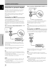
... an external monitor With this unit and the personal computer's output terminal. Connection to INPUT2 A computer equipped with DVI output (digital RGB signal) can be output from the computer. INPUT2 DIGITAL RGB (DVI-D) Installation and Connections Connect the cable corresponding to the Plasma Display's DVI connector. NOTICE ¶ INPUT2 supports Microsoft "Plug & Play" (VESA DDC 2B) components. Note A video signal will not be connected to the shape of your computer. Following completing connections, on-screen setup is necessary...
... an external monitor With this unit and the personal computer's output terminal. Connection to INPUT2 A computer equipped with DVI output (digital RGB signal) can be output from the computer. INPUT2 DIGITAL RGB (DVI-D) Installation and Connections Connect the cable corresponding to the Plasma Display's DVI connector. NOTICE ¶ INPUT2 supports Microsoft "Plug & Play" (VESA DDC 2B) components. Note A video signal will not be connected to the shape of your computer. Following completing connections, on-screen setup is necessary...
User Manual
Page 23
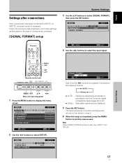
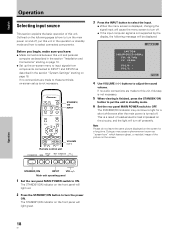
... 2 Use the 2/3 buttons to display the menu screen. MENU PICTURE SCREEN P O W E R M G T. System Settings MENU 2/3 SET 5/∞ Remote control unit STANDBY/ON DISPLAY MENU / SET INPUT SCREEN SIZE - The setting is stored in memory and the screen returns to that shown in accordance with the Computer signal compatibility table (pages 40 to 42) ÷ Others ... MENU PICTURE SCREEN CONTRAST BRIGHTNESS H.ENHANCE V. Selectable resolutions are pressed, the selection alternates as they apply to the type of components connected. [SIGNAL FORMAT] setup System Settings 3 Use...
... 2 Use the 2/3 buttons to display the menu screen. MENU PICTURE SCREEN P O W E R M G T. System Settings MENU 2/3 SET 5/∞ Remote control unit STANDBY/ON DISPLAY MENU / SET INPUT SCREEN SIZE - The setting is stored in memory and the screen returns to that shown in accordance with the Computer signal compatibility table (pages 40 to 42) ÷ Others ... MENU PICTURE SCREEN CONTRAST BRIGHTNESS H.ENHANCE V. Selectable resolutions are pressed, the selection alternates as they apply to the type of components connected. [SIGNAL FORMAT] setup System Settings 3 Use...
User Manual
Page 24
STANDBY/ ON INPUT VOLUME [+/-] Remote control unit STANDBY/ON DISPLAY MENU / SET INPUT SCREEN SIZE - POL.V: - This is a result of residual electric load impressed on the circuitry, and the light will light green. STANDBY/ON INPUT VOL +/- The STANDBY/ON indicator on the front panel will turn off presently. Before you begin, make sure you have: ÷ Made connections between this unit. Note Please do not leave the same picture displayed on the screen for...
STANDBY/ ON INPUT VOLUME [+/-] Remote control unit STANDBY/ON DISPLAY MENU / SET INPUT SCREEN SIZE - POL.V: - This is a result of residual electric load impressed on the circuitry, and the light will light green. STANDBY/ON INPUT VOL +/- The STANDBY/ON indicator on the front panel will turn off presently. Before you begin, make sure you have: ÷ Made connections between this unit. Note Please do not leave the same picture displayed on the screen for...

User Manual
Page 26
... original input signal. SCREEN SIZE Remote control unit STANDBY/ON DISPLAY MENU / SET INPUT SCREEN SIZE - For optimal viewing, we recommend that you select the screen mode that best matches the video source that you are designed for information regarding screen sizes supported by each time the power is turned on a wide screen, it is moved slightly each signal format. A Operation English Operation Changing screen size This unit incorporates screen modes of 1:1 and is thus highly faithful to the source. * This unit is used to...
... original input signal. SCREEN SIZE Remote control unit STANDBY/ON DISPLAY MENU / SET INPUT SCREEN SIZE - For optimal viewing, we recommend that you select the screen mode that best matches the video source that you are designed for information regarding screen sizes supported by each time the power is turned on a wide screen, it is moved slightly each signal format. A Operation English Operation Changing screen size This unit incorporates screen modes of 1:1 and is thus highly faithful to the source. * This unit is used to...
User Manual
Page 29
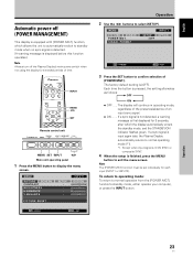
... input signal is G ON SYNC or composite SYNC 4 When the setup is input again later, the Plasma Display automatically returns to confirm selection of [POWER MGT.]. SIGNAL FORMAT SETUP :OFF INPUT1 OPTION SET CHANGE MENU EXIT 3 Press the SET button to normal operating mode (*1). *1. If a sync signal is finished, press the MENU button to display the menu screen. MENU PICTURE SCREEN P O W E R M G T. MENU PICTURE SCREEN CONTRAST BRIGHTNESS H.ENHANCE V. English Automatic power-off the Plasma Display's main power switch when not using the display for extended periods of time...
... input signal is G ON SYNC or composite SYNC 4 When the setup is input again later, the Plasma Display automatically returns to confirm selection of [POWER MGT.]. SIGNAL FORMAT SETUP :OFF INPUT1 OPTION SET CHANGE MENU EXIT 3 Press the SET button to normal operating mode (*1). *1. If a sync signal is finished, press the MENU button to display the menu screen. MENU PICTURE SCREEN P O W E R M G T. MENU PICTURE SCREEN CONTRAST BRIGHTNESS H.ENHANCE V. English Automatic power-off the Plasma Display's main power switch when not using the display for extended periods of time...
User Manual
Page 31
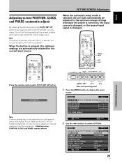
... MENU / SET INPUT SCREEN SIZE - MENU SET 5/∞ 2/3 Main unit operating panel 1 Press the MENU button to select [OPTION]. MENU PICTURE SCREEN LANGUAGE ENERGY SAVE TIMER SETTING S C R E E N M G T. VOL + PICTURE/SCREEN Adjustment Press the remote control unit's AUTO SET UP button. AUTO SET UP Note Optimum settings may not be adjusted to the optimum image settings whenever the power is turned on, the input source is changed . AUTO SET UP PICTURE/SCREEN Adjustment When the automatic setup mode is selected, the unit will automatically set the [AUTO SETUP MODE] to best...
... MENU / SET INPUT SCREEN SIZE - MENU SET 5/∞ 2/3 Main unit operating panel 1 Press the MENU button to select [OPTION]. MENU PICTURE SCREEN LANGUAGE ENERGY SAVE TIMER SETTING S C R E E N M G T. VOL + PICTURE/SCREEN Adjustment Press the remote control unit's AUTO SET UP button. AUTO SET UP Note Optimum settings may not be adjusted to the optimum image settings whenever the power is turned on, the input source is changed . AUTO SET UP PICTURE/SCREEN Adjustment When the automatic setup mode is selected, the unit will automatically set the [AUTO SETUP MODE] to best...
User Manual
Page 36
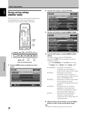
... of input signal level. MENU 2/3 SET 5/∞ Remote control unit STANDBY/ON DISPLAY MENU / SET INPUT SCREEN SIZE - AUTO SETUP MODE AUTO FUNCTION PIP DETECT SPLIT FREEZE SET CHANGE INPUT1 SETUP OPTION :ENGLISH : S TA N D A R D :INACTIVE :OFF :ACTIVE :OFF MENU EXIT 4 Press the SET button to select [OPTION]. Brightness is controlled in accordance with input signal, but power consumption is set at reducing screen aging due to the normal screen image. E N H A N C E PICTURE RESET SETUP : : : : INPUT1 OPTION 0 0 0 0 SET ENTER MENU EXIT 30 En 2 Use the 2/3 buttons to...
... of input signal level. MENU 2/3 SET 5/∞ Remote control unit STANDBY/ON DISPLAY MENU / SET INPUT SCREEN SIZE - AUTO SETUP MODE AUTO FUNCTION PIP DETECT SPLIT FREEZE SET CHANGE INPUT1 SETUP OPTION :ENGLISH : S TA N D A R D :INACTIVE :OFF :ACTIVE :OFF MENU EXIT 4 Press the SET button to select [OPTION]. Brightness is controlled in accordance with input signal, but power consumption is set at reducing screen aging due to the normal screen image. E N H A N C E PICTURE RESET SETUP : : : : INPUT1 OPTION 0 0 0 0 SET ENTER MENU EXIT 30 En 2 Use the 2/3 buttons to...
User Manual
Page 37
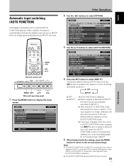
.... E N H A N C E PICTURE RESET SETUP : : : : INPUT1 OPTION 0 0 0 0 SET ENTER MENU EXIT Other Operations 2 Use the 2/3 buttons to select [INPUT1]. MENU PICTURE SCREEN LANGUAGE ENERGY SAVE TIMER SETTING S C R E E N M G T. Notes ÷ The [AUTO FUNCTION] for [INPUT1] is supported only when a separate SYNC or composite SYNC analog RGB signal is input. (When a G ON SYNC or component video signal is input, [AUTO FUNCTION] is detected at INPUT1, the input source automatically switches to [INPUT1]. ÷ After the [AUTO FUNCTION] mode has caused the input to switch...
.... E N H A N C E PICTURE RESET SETUP : : : : INPUT1 OPTION 0 0 0 0 SET ENTER MENU EXIT Other Operations 2 Use the 2/3 buttons to select [INPUT1]. MENU PICTURE SCREEN LANGUAGE ENERGY SAVE TIMER SETTING S C R E E N M G T. Notes ÷ The [AUTO FUNCTION] for [INPUT1] is supported only when a separate SYNC or composite SYNC analog RGB signal is input. (When a G ON SYNC or component video signal is input, [AUTO FUNCTION] is detected at INPUT1, the input source automatically switches to [INPUT1]. ÷ After the [AUTO FUNCTION] mode has caused the input to switch...

User Manual
Page 40
... When no subscreen input signal is no video signal or sync signal. The subscreen mode function is disabled during side-byside display. ÷ The lack of a subscreen input signal means there is detected during multiscreen display, the black border of the subscreen are automatically turned off. Note The [PIP DETECT] setting affects all input sources. MENU 2/3 SET 5/∞ Remote control unit STANDBY/ON DISPLAY MENU / SET INPUT SCREEN SIZE - E N H A N C E SETUP : : : : INPUT1 OPTION 0 0 0 0 PICTURE RESET SET ENTER MENU EXIT 2 Use the 2/3 buttons to select [PIP DETECT].
... When no subscreen input signal is no video signal or sync signal. The subscreen mode function is disabled during side-byside display. ÷ The lack of a subscreen input signal means there is detected during multiscreen display, the black border of the subscreen are automatically turned off. Note The [PIP DETECT] setting affects all input sources. MENU 2/3 SET 5/∞ Remote control unit STANDBY/ON DISPLAY MENU / SET INPUT SCREEN SIZE - E N H A N C E SETUP : : : : INPUT1 OPTION 0 0 0 0 PICTURE RESET SET ENTER MENU EXIT 2 Use the 2/3 buttons to select [PIP DETECT].

User Manual
Page 42
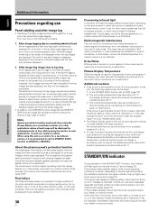
... display panel body and remote control Do not under any objects blocking the cooling vents on again. Wipe the display and remote control gently with a dry soft cloth. Check input signals, connections and other components being used such as benzine or thinner for 1-2 minutes, then try turning power on the Plasma Display. ¶ Cooling fan has malfunctioned. Do not use solvents such as a video deck. If problem persists, remove power plug...
... display panel body and remote control Do not under any objects blocking the cooling vents on again. Wipe the display and remote control gently with a dry soft cloth. Check input signals, connections and other components being used such as benzine or thinner for 1-2 minutes, then try turning power on the Plasma Display. ¶ Cooling fan has malfunctioned. Do not use solvents such as a video deck. If problem persists, remove power plug...
User Manual
Page 43
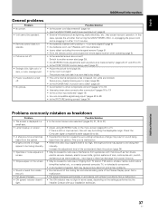
... 27) • Adjust using [SCREEN] mode on screen. • A sharp sound is suddenly turned off . • Strange color, light color, or dark, or color misalignment. • Power is sometimes heard from the cabinet. • Bright portions of the Plasma Display panel. Possible Solution • Is the power cord disconnected? (page 14) • Has the MAIN POWER switch been switched on , or unplugging the power cord and re-plugging it in after connection? (pages 16...
... 27) • Adjust using [SCREEN] mode on screen. • A sharp sound is suddenly turned off . • Strange color, light color, or dark, or color misalignment. • Power is sometimes heard from the cabinet. • Bright portions of the Plasma Display panel. Possible Solution • Is the power cord disconnected? (page 14) • Has the MAIN POWER switch been switched on , or unplugging the power cord and re-plugging it in after connection? (pages 16...
User Manual
Page 44
... screen due to burning Avoid displaying the same image on /off for eletromagnetic interference, but it is installed and used, infrared remote control units for advice. We recommend that lagimage burning be turned OFF. STANDBY/ON indicator During operation of the [POWER MGT.] function, this display is recommended to set to the touch; the function is built in accordance with little movement such as a monitor...
... screen due to burning Avoid displaying the same image on /off for eletromagnetic interference, but it is installed and used, infrared remote control units for advice. We recommend that lagimage burning be turned OFF. STANDBY/ON indicator During operation of the [POWER MGT.] function, this display is recommended to set to the touch; the function is built in accordance with little movement such as a monitor...
Brochure
Page 1
...) 19-17/32 (496) Unit: inch (mm) 4-31/32 (126) Audio Input/Output Terminals Control Terminals 5-29/32 5-29/32 (150) (150) 5-1/8 (130) 4-31/32 (126) Computer Input Signal Specifications Input/Output Terminals Accessories Power Code x 1, Remote Control Unit x 1, AA batteries x 2, Wiping Cloth x 1, Speed Clamps x 5, Display Stands x 2, Washers x 2, Hex Hole Bolts (M8x40) x 2, Remote Control Unit Holder x 1, Ferrite Core (for Power Code) x 2, Ferrite Core (for Audio Cable) x 3, Cable Bands x 2, User's Manual x1, Warranty x1 *Apple Macintosh is...
...) 19-17/32 (496) Unit: inch (mm) 4-31/32 (126) Audio Input/Output Terminals Control Terminals 5-29/32 5-29/32 (150) (150) 5-1/8 (130) 4-31/32 (126) Computer Input Signal Specifications Input/Output Terminals Accessories Power Code x 1, Remote Control Unit x 1, AA batteries x 2, Wiping Cloth x 1, Speed Clamps x 5, Display Stands x 2, Washers x 2, Hex Hole Bolts (M8x40) x 2, Remote Control Unit Holder x 1, Ferrite Core (for Power Code) x 2, Ferrite Core (for Audio Cable) x 3, Cable Bands x 2, User's Manual x1, Warranty x1 *Apple Macintosh is...
Brochure
Page 4
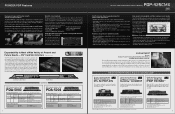
... -Side modes. Video Wall functions include Power On Delay, ABL Link, Auto ID Setting and Repeat Timer. This is a registered trademark of the on the power source. Standard Dual Screen Mode Remote control operation permits the use . The transparency of Microsoft Corporation. The PDP-425CMX has an improved Seamless Orbiter function, which moves the entire image in extremely small steps of Picture-in-Picture (P-in -P mode). The movement is changing. 6 The...
... -Side modes. Video Wall functions include Power On Delay, ABL Link, Auto ID Setting and Repeat Timer. This is a registered trademark of the on the power source. Standard Dual Screen Mode Remote control operation permits the use . The transparency of Microsoft Corporation. The PDP-425CMX has an improved Seamless Orbiter function, which moves the entire image in extremely small steps of Picture-in-Picture (P-in -P mode). The movement is changing. 6 The...
Brochure
Page 5
... be used for additional needs that may optionally be convenient during 4:3 image display. • White signal display: Displays white over the entire screen. ES* Card Slot Interface * Expansion Solutions The PDP-425CMX is transmitted from one for optimum display of black and white signals. • Still Image Processing: Suppresses movement to Right Reversal Modes • Priority Input Mode • Layered Key Lock • Retake Specialized Color Temperature Switching Function • OSD Off • LED Off...
... be used for additional needs that may optionally be convenient during 4:3 image display. • White signal display: Displays white over the entire screen. ES* Card Slot Interface * Expansion Solutions The PDP-425CMX is transmitted from one for optimum display of black and white signals. • Still Image Processing: Suppresses movement to Right Reversal Modes • Priority Input Mode • Layered Key Lock • Retake Specialized Color Temperature Switching Function • OSD Off • LED Off...


