User Manual
Page 3
...and set up the product. Notes on Installation Work: This product is marketed assuming that it useful in a safe place. Keep this manual in the future. i En Note for damage caused by qualified personnel with enough skill and competence. You will know how to operate... the Plasma Display properly. PIONEER cannot assume liabilities for Dealers: After installation, be sure to handle the product. English Français Safety Precautions Operating Instructions Thank ...
...and set up the product. Notes on Installation Work: This product is marketed assuming that it useful in a safe place. Keep this manual in the future. i En Note for damage caused by qualified personnel with enough skill and competence. You will know how to operate... the Plasma Display properly. PIONEER cannot assume liabilities for Dealers: After installation, be sure to handle the product. English Français Safety Precautions Operating Instructions Thank ...
User Manual
Page 6
...Limited Warranty sheet included with Video Card Model Number: PDP-425CMX (Plasma Display) PDA-5003/PDA-5004 (Video Card) Product Category: Class B Personal Computers & Peripherals Responsible Party Name: PIONEER ELECTRONICS SERVICE, INC. English Safety Precautions FEDERAL COMMUNICATIONS...with your product. Address: 1925E. Customer Support Division P.O. and you wish to locate the nearest Pioneer Authorized Independent Service Company, or if you wish to purchase replacement parts, operating instructions, service manuals, or accessories, please call the number shown below. 8 0 0 - 8 7 2 ...
...Limited Warranty sheet included with Video Card Model Number: PDP-425CMX (Plasma Display) PDA-5003/PDA-5004 (Video Card) Product Category: Class B Personal Computers & Peripherals Responsible Party Name: PIONEER ELECTRONICS SERVICE, INC. English Safety Precautions FEDERAL COMMUNICATIONS...with your product. Address: 1925E. Customer Support Division P.O. and you wish to locate the nearest Pioneer Authorized Independent Service Company, or if you wish to purchase replacement parts, operating instructions, service manuals, or accessories, please call the number shown below. 8 0 0 - 8 7 2 ...
User Manual
Page 7
English Contents Safety Precautions i Features 2 Before Proceeding 3 How to use this manual 3 Checking supplied accessories 5 Part Names and Functions 6 Main unit 6 Remote control unit 7 Connection panel 8 Installation and Connections 10 Installation of the unit 10 Connection to a ...
English Contents Safety Precautions i Features 2 Before Proceeding 3 How to use this manual 3 Checking supplied accessories 5 Part Names and Functions 6 Main unit 6 Remote control unit 7 Connection panel 8 Installation and Connections 10 Installation of the unit 10 Connection to a ...
User Manual
Page 9
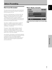
... remote control unit, as their respective buttons and controls will be referred to follow the course of actions and operations in this manual is set up to throughout this manual. E N H A N C E PICTURE RESET SETUP : : : : INPUT1 OPTION 0 0 0 0 SET ENTER MENU EXIT Images shown here may be necessary. ...been taken out of the box and it may differ from the actual display image. English Before Proceeding How to use this manual This manual is dedicated to the basic operations associated with selecting a source component up to the more complex operations associated with adjusting the ...
... remote control unit, as their respective buttons and controls will be referred to follow the course of actions and operations in this manual is set up to throughout this manual. E N H A N C E PICTURE RESET SETUP : : : : INPUT1 OPTION 0 0 0 0 SET ENTER MENU EXIT Images shown here may be necessary. ...been taken out of the box and it may differ from the actual display image. English Before Proceeding How to use this manual This manual is dedicated to the basic operations associated with selecting a source component up to the more complex operations associated with adjusting the ...
User Manual
Page 10
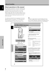
English Before Proceeding About operations in this manual Each operation is finished, press the MENU button to exit the menu screen. MENU 2/3 SET 5/∞ Remote control unit STANDBY/ON DISPLAY MENU / SET INPUT ...
English Before Proceeding About operations in this manual Each operation is finished, press the MENU button to exit the menu screen. MENU 2/3 SET 5/∞ Remote control unit STANDBY/ON DISPLAY MENU / SET INPUT ...
User Manual
Page 16
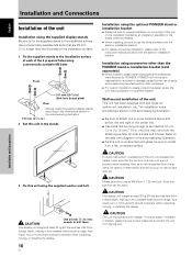
...back depth, making it very unstable when stood on edge. Also, as hot air is constructed with glass, be sure to the instruction manual provided with bolt holes for wall-mount installation, etc. Installation using accessories other companies. ÷ For custom installation, please consult the ...front- As a result, two or more persons should cooperate when unpacking, moving , or installing the display. 10 En Installation using the optional PIONEER stand or installation bracket ÷ Please be sure to -back depth, making it on the main unit are not blocked when installing. The ...
...back depth, making it very unstable when stood on edge. Also, as hot air is constructed with glass, be sure to the instruction manual provided with bolt holes for wall-mount installation, etc. Installation using accessories other companies. ÷ For custom installation, please consult the ...front- As a result, two or more persons should cooperate when unpacking, moving , or installing the display. 10 En Installation using the optional PIONEER stand or installation bracket ÷ Please be sure to -back depth, making it on the main unit are not blocked when installing. The ...
User Manual
Page 18
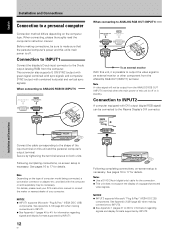
.... See pages 16 to 17 for details. Secure by tightening the terminal screws on this unit is off . For details, please read the computer's instruction manual. Connection to INPUT1 Connect the display's D-sub input connector to an external monitor or other component from the computer. Note A video signal will not be... output the video signal to the D-sub output (analog RGB) from the ANALOG RGB OUT (INPUT1) terminal. When connecting, please thoroughly read your PC's instruction manual or consult the maker or nearest dealer of your computer.
.... See pages 16 to 17 for details. Secure by tightening the terminal screws on this unit is off . For details, please read the computer's instruction manual. Connection to INPUT1 Connect the display's D-sub input connector to an external monitor or other component from the computer. Note A video signal will not be... output the video signal to the D-sub output (analog RGB) from the ANALOG RGB OUT (INPUT1) terminal. When connecting, please thoroughly read your PC's instruction manual or consult the maker or nearest dealer of your computer.
User Manual
Page 31
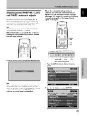
... the [AUTO SETUP MODE] to best match the current image input. In such cases, set the screen position and clock to [INACTIVE], and use the manual adjustment methods explained in the following section, "Adjusting screen POSITION, CLOCK, and PHASE ". MENU PICTURE SCREEN CONTRAST BRIGHTNESS H.ENHANCE V. AUTO SETUP MODE AUTO FUNCTION PIP...
... the [AUTO SETUP MODE] to best match the current image input. In such cases, set the screen position and clock to [INACTIVE], and use the manual adjustment methods explained in the following section, "Adjusting screen POSITION, CLOCK, and PHASE ". MENU PICTURE SCREEN CONTRAST BRIGHTNESS H.ENHANCE V. AUTO SETUP MODE AUTO FUNCTION PIP...

User Manual
Page 32
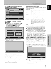
... is pressed, the setting alternates as follows: 3 INACTIVE ACTIVE 2 5 When finished with the setting, press the MENU button to return to [INACTIVE], and use the manual adjustment methods explained in the following section, "Adjusting screen POSITION, CLOCK, and PHASE ". VOL + MENU SET 5/∞ 2/3 Main unit operating panel 1 Press the MENU button...
... is pressed, the setting alternates as follows: 3 INACTIVE ACTIVE 2 5 When finished with the setting, press the MENU button to return to [INACTIVE], and use the manual adjustment methods explained in the following section, "Adjusting screen POSITION, CLOCK, and PHASE ". VOL + MENU SET 5/∞ 2/3 Main unit operating panel 1 Press the MENU button...
User Manual
Page 33
...; buttons to select the desired value. ÷ When the [POSITION] item is minimum flicker of screen letters or color misalignment. If you wish to record a manually set adjustment value, set in the Vertical direction (V). SCREEN RESET ? V Adjust the picture's position upward or downward. YES NO SET SET MENU EXIT 2 Use the...
...; buttons to select the desired value. ÷ When the [POSITION] item is minimum flicker of screen letters or color misalignment. If you wish to record a manually set adjustment value, set in the Vertical direction (V). SCREEN RESET ? V Adjust the picture's position upward or downward. YES NO SET SET MENU EXIT 2 Use the...
Brochure
Page 1
... FAX : 310-952-2639 http://www.pioneerelectronics.com/ http://www.pioneerindustrialav.com Pioneer Corporation and Pioneer Display Products Corporation where PDP products are registered trademarks of Pioneer Corporation. Printed on Recycled Paper 3147E AD-FC(F)01-06 Printed in may ...M8x40) x 2, Remote Control Unit Holder x 1, Ferrite Core (for Power Code) x 2, Ferrite Core (for Audio Cable) x 3, Cable Bands x 2, User's Manual x1, Warranty x1 *Apple Macintosh is a registered trademark of Apple Computer, Inc. *IBM PC/AT is a registered trademark of IBM Corporation. *Microsoft is a registered ...
... FAX : 310-952-2639 http://www.pioneerelectronics.com/ http://www.pioneerindustrialav.com Pioneer Corporation and Pioneer Display Products Corporation where PDP products are registered trademarks of Pioneer Corporation. Printed on Recycled Paper 3147E AD-FC(F)01-06 Printed in may ...M8x40) x 2, Remote Control Unit Holder x 1, Ferrite Core (for Power Code) x 2, Ferrite Core (for Audio Cable) x 3, Cable Bands x 2, User's Manual x1, Warranty x1 *Apple Macintosh is a registered trademark of Apple Computer, Inc. *IBM PC/AT is a registered trademark of IBM Corporation. *Microsoft is a registered ...


