
Service Manual
Page 1
Component CD MD TUNER CD TUNER DECK STEREO POWER AMPLIFIER SPEAKER SYSTEM System IS-21MD IS-21T XC-IS21MD --- --- SAFETY INFORMATION 2 2. PCB CONNECTION DIAGRAM 8 5. P.O. GENERAL INFORMATION 17 7.1 SINGLE OPERATION METHOD 17 8. Box 1760, Long Beach, CA 90801-1760, U.S.A. Haven 1087, Keetberglaan 1, 9120 Melsele, Belgium PIONEER ELECTRONICS ASIACENTRE PTE. Type Model M-IS21 Power Requirement Remarks MYXJ AC220-230V NVXJ AC230V This product is a component of a system. PCB PARTS LIST...
Component CD MD TUNER CD TUNER DECK STEREO POWER AMPLIFIER SPEAKER SYSTEM System IS-21MD IS-21T XC-IS21MD --- --- SAFETY INFORMATION 2 2. PCB CONNECTION DIAGRAM 8 5. P.O. GENERAL INFORMATION 17 7.1 SINGLE OPERATION METHOD 17 8. Box 1760, Long Beach, CA 90801-1760, U.S.A. Haven 1087, Keetberglaan 1, 9120 Melsele, Belgium PIONEER ELECTRONICS ASIACENTRE PTE. Type Model M-IS21 Power Requirement Remarks MYXJ AC220-230V NVXJ AC230V This product is a component of a system. PCB PARTS LIST...
Service Manual
Page 2
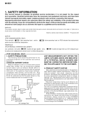
... CANADIAN MODEL ONLY) Fuse symbols (fast operating fuse) and/or parts must not exceed 0.5 mA. Plug the AC line cord of identical designation. (slow operating fuse) on . These are not qualified to a known earth ground (water pipe, conduit, etc.) by using replacement components rated for qualified service technicians; For the latest information, always consult the current PIONEER Service Manual. Qualified technicians have the necessary test equipment and...
... CANADIAN MODEL ONLY) Fuse symbols (fast operating fuse) and/or parts must not exceed 0.5 mA. Plug the AC line cord of identical designation. (slow operating fuse) on . These are not qualified to a known earth ground (water pipe, conduit, etc.) by using replacement components rated for qualified service technicians; For the latest information, always consult the current PIONEER Service Manual. Qualified technicians have the necessary test equipment and...
Service Manual
Page 3
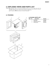
Screws adjacent to use parts of the part. AHA7238 AHA7239 AHD7747 AHG7053 3 3 The mark found on product are not in our Master Spare Parts List. Description 1 Side Pad AL 2 Side Pad AR 3 Packing Case AMP MY 4 Packing Sheet Part No. EXPLODED VIEWS AND PARTS LIST NOTES: Parts marked by "NSP" are generally unavailable because they are used for disassembly. 2.1 PACKING 4 1 2 ¶ PACKING PARTS LIST Mark No. M-IS21 2. Therefore, when replacing, be sure to mark on some component parts indicates the importance of the safety factor of identical designation.
Screws adjacent to use parts of the part. AHA7238 AHA7239 AHD7747 AHG7053 3 3 The mark found on product are not in our Master Spare Parts List. Description 1 Side Pad AL 2 Side Pad AR 3 Packing Case AMP MY 4 Packing Sheet Part No. EXPLODED VIEWS AND PARTS LIST NOTES: Parts marked by "NSP" are generally unavailable because they are used for disassembly. 2.1 PACKING 4 1 2 ¶ PACKING PARTS LIST Mark No. M-IS21 2. Therefore, when replacing, be sure to mark on some component parts indicates the importance of the safety factor of identical designation.
Service Manual
Page 5
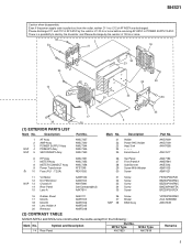
...Part No. Please discharge C11 and C12 of AF ASSY by the resistor of 100 Ω or more before removing AF ASSY or POWER SUPPLY ASSY. MYXJ Type 14 Rear Panel ANC7823 NVXJ Type ANC7839 VPZ30P080FMC ZCA-SKB90BK AWU7349 Remarks 5 ANG7009 ANG7109 ANH7058 AAK7617 6 HP Assy 7 METER Assy 8 METER CONNECT Assy 9 Power Transformer 10 Fuse...33 3 (1) EXTERIOR PARTS LIST Mark No. AWU7337 AWU7340 AWU7344 AWU7345 AWU7350 Mark No. 21 22 23 24 25 Description Holder Power PAC Holder Heat Sink Escutcheon A Part No. Description 1 2 3 NSP 4 NSP 5 AF Assy AMP Assy POWER SUPPLY Assy PRIMARY ...
...Part No. Please discharge C11 and C12 of AF ASSY by the resistor of 100 Ω or more before removing AF ASSY or POWER SUPPLY ASSY. MYXJ Type 14 Rear Panel ANC7823 NVXJ Type ANC7839 VPZ30P080FMC ZCA-SKB90BK AWU7349 Remarks 5 ANG7009 ANG7109 ANH7058 AAK7617 6 HP Assy 7 METER Assy 8 METER CONNECT Assy 9 Power Transformer 10 Fuse...33 3 (1) EXTERIOR PARTS LIST Mark No. AWU7337 AWU7340 AWU7344 AWU7345 AWU7350 Mark No. 21 22 23 24 25 Description Holder Power PAC Holder Heat Sink Escutcheon A Part No. Description 1 2 3 NSP 4 NSP 5 AF Assy AMP Assy POWER SUPPLY Assy PRIMARY ...
Service Manual
Page 6
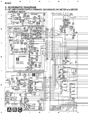
SCHEMATIC DIAGRAM 3.1 AF, AMP, POWER SUPPLY, PRIMARY, SECONDARY, HP, METER and METER CONNECT ASSYS A B B AMP ASSY (AWU7340) C C POWER SUPPLY ASSY (AWU7344) D 6ABC 1 2 3 4 1 2 3 4 M-IS21 3.
SCHEMATIC DIAGRAM 3.1 AF, AMP, POWER SUPPLY, PRIMARY, SECONDARY, HP, METER and METER CONNECT ASSYS A B B AMP ASSY (AWU7340) C C POWER SUPPLY ASSY (AWU7344) D 6ABC 1 2 3 4 1 2 3 4 M-IS21 3.
Service Manual
Page 7
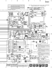
...AUDIO SIGNAL ROUTE 7 8 M-IS21 Note : When ordering service parts, be sure to refer to "EXPLODED VIEWS and PARTS LIST" or "PCB PARTS LIST" A B F HP ASSY (AWU7351) G METER ASSY (AWU7353) H METER CONNECT ASSY (AWU7356) D PRIMARY ASSY (AWU7345) C E SECONDARY ASSY (AWU7350) CAUTION : FOR CONTINUED PROTECTION AGAINST RISK OF FIRE, REPLACE...AC POWER CORD MYXJ TYPE : XDG3001 NVXJ TYPE : ADG1156 D AC220-230V A AF ASSY (AWU7337) • NOTE FOR FUSE REPLACEMENT CAUTION -FOR CONTINUED PROTECTION AGAINST RISK OF FIRE. CAUTION : FOR CONTINUED PROTECTION AGAINST RISK OF FIRE, REPLACE ONLY...
...AUDIO SIGNAL ROUTE 7 8 M-IS21 Note : When ordering service parts, be sure to refer to "EXPLODED VIEWS and PARTS LIST" or "PCB PARTS LIST" A B F HP ASSY (AWU7351) G METER ASSY (AWU7353) H METER CONNECT ASSY (AWU7356) D PRIMARY ASSY (AWU7345) C E SECONDARY ASSY (AWU7350) CAUTION : FOR CONTINUED PROTECTION AGAINST RISK OF FIRE, REPLACE...AC POWER CORD MYXJ TYPE : XDG3001 NVXJ TYPE : ADG1156 D AC220-230V A AF ASSY (AWU7337) • NOTE FOR FUSE REPLACEMENT CAUTION -FOR CONTINUED PROTECTION AGAINST RISK OF FIRE. CAUTION : FOR CONTINUED PROTECTION AGAINST RISK OF FIRE, REPLACE ONLY...
Service Manual
Page 8
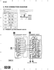
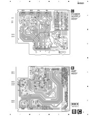
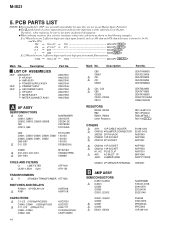
A comparison between the main parts of PCB diagrams Connector Capacitor SIDE A BCE B C EB C E Transistor with the schematic diagram. Part numbers in PCB diagrams match those in Schematic Diagrams B C EB C E Part Name Transistor 4. PCB CONNECTION DIAGRAM A NOTE FOR PCB DIAGRAMS: 1. Viewpoint of PCB and schematic For further information for several destination. 2. The parts mounted on this PCB include all necessary parts diagrams. for respective destinations, be sure diagrams is shown below...
A comparison between the main parts of PCB diagrams Connector Capacitor SIDE A BCE B C EB C E Transistor with the schematic diagram. Part numbers in PCB diagrams match those in Schematic Diagrams B C EB C E Part Name Transistor 4. PCB CONNECTION DIAGRAM A NOTE FOR PCB DIAGRAMS: 1. Viewpoint of PCB and schematic For further information for several destination. 2. The parts mounted on this PCB include all necessary parts diagrams. for respective destinations, be sure diagrams is shown below...
Service Manual
Page 9
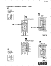
1 2 3 4.2 HP, METER and METER CONNECT ASSYS H METER CONNECT ASSY G METER ASSY 4 M-IS21 A F HP ASSY A CN3105 B A CN3104 (ANP7300-C) H METER CONNECT ASSY 1 POWER METER G METER ASSY Q5604 IC5601 Q5601 Q5602 Q5603 SIDE A F C HP ASSY D (ANP7300-C) SIDE B FGH9 2 3 4
1 2 3 4.2 HP, METER and METER CONNECT ASSYS H METER CONNECT ASSY G METER ASSY 4 M-IS21 A F HP ASSY A CN3105 B A CN3104 (ANP7300-C) H METER CONNECT ASSY 1 POWER METER G METER ASSY Q5604 IC5601 Q5601 Q5602 Q5603 SIDE A F C HP ASSY D (ANP7300-C) SIDE B FGH9 2 3 4
Service Manual
Page 13
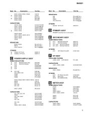
1 2 3 4 M-IS21 C POWER SUPPLY A IC32 ASSY Q31 Q41 Q3652 Q3653 B Q3311 Q3312 Q3503 IC3502 IC3501 B AMP C ASSY Q3353 Q3354 D SIDE B (ANP7300-C) B C 13 1 2 3 4
1 2 3 4 M-IS21 C POWER SUPPLY A IC32 ASSY Q31 Q41 Q3652 Q3653 B Q3311 Q3312 Q3503 IC3502 IC3501 B AMP C ASSY Q3353 Q3354 D SIDE B (ANP7300-C) B C 13 1 2 3 4
Service Manual
Page 14
...replacing, be sure to use parts of the part. Ex.1 When there are 2 effective digits (any digit apart from 0), such as 560 ohm and 47k ohm (tolerance is shown by "NSP" are generally unavailable because they are 3 effective digits... T1 STANDBY TRANSFORMER ATT7050 SWITCHES AND ...CABLE HOLDER CN3105 4PJUMPER CONNECTOR JA3333 2P PIN JACK CN3332 10P SOCKET CN3103 5P SOCKET 51048-1200 52151-0410 AKB7043 AKP7048 AKP7051 CN3106 11P SOCKET CN3102 14P SOCKET H1, H2 FUSE CLIP AN1 AC INLET 1P J3001 JUMPER WIRE AKP7052 AKP7053 AKR7001 BKP1046 D20PYY1220E CN3331 4P SPEAKER TERMINAL XKE3001 B AMP...
...replacing, be sure to use parts of the part. Ex.1 When there are 2 effective digits (any digit apart from 0), such as 560 ohm and 47k ohm (tolerance is shown by "NSP" are generally unavailable because they are 3 effective digits... T1 STANDBY TRANSFORMER ATT7050 SWITCHES AND ...CABLE HOLDER CN3105 4PJUMPER CONNECTOR JA3333 2P PIN JACK CN3332 10P SOCKET CN3103 5P SOCKET 51048-1200 52151-0410 AKB7043 AKP7048 AKP7051 CN3106 11P SOCKET CN3102 14P SOCKET H1, H2 FUSE CLIP AN1 AC INLET 1P J3001 JUMPER WIRE AKP7052 AKP7053 AKR7001 BKP1046 D20PYY1220E CN3331 4P SPEAKER TERMINAL XKE3001 B AMP...
Service Manual
Page 15
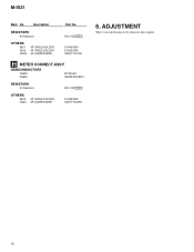
...PLUG Part No. E SECONDARY ASSY SEMICONDUCTORS IC41 PROTECTOR(3.5A) IC31 PROTECTOR(4A) IC21, IC22 PROTECTOR(5A) IC11, IC12 PROTECTOR(7A) OTHERS 3001 12P CABLE HOLDER F HP ASSY COILS AND FILTERS L3992-L3994 CHIP BEADS CAPACITORS C3991, C3995, C3996 RESISTORS R3991, R3992 OTHERS 3004 3991 J3004 5P CABLE HOLDER MINI JACK 5P JUMPER WIRE...no service part. ...PLUG Part No. 1SS133 LT2A03 MTZJ10C MTZJ18B MTZJ39C CCSQCH100D50 CCSQCH680J50 CEANP100M35 CEANP2R2M50 CEAT101M50 CEAT1R0M50 CEAT470M25 CKSQYB332K50 CKSQYB682K50 CKSQYB822K50 RD1/4PU101J RD1/4PU104J RS1/10S J AKM7010 AKM7011 C POWER...
...PLUG Part No. E SECONDARY ASSY SEMICONDUCTORS IC41 PROTECTOR(3.5A) IC31 PROTECTOR(4A) IC21, IC22 PROTECTOR(5A) IC11, IC12 PROTECTOR(7A) OTHERS 3001 12P CABLE HOLDER F HP ASSY COILS AND FILTERS L3992-L3994 CHIP BEADS CAPACITORS C3991, C3995, C3996 RESISTORS R3991, R3992 OTHERS 3004 3991 J3004 5P CABLE HOLDER MINI JACK 5P JUMPER WIRE...no service part. ...PLUG Part No. 1SS133 LT2A03 MTZJ10C MTZJ18B MTZJ39C CCSQCH100D50 CCSQCH680J50 CEANP100M35 CEANP2R2M50 CEAT101M50 CEAT1R0M50 CEAT470M25 CKSQYB332K50 CKSQYB682K50 CKSQYB822K50 RD1/4PU101J RD1/4PU104J RS1/10S J AKM7010 AKM7011 C POWER...
Service Manual
Page 16
ADJUSTMENT There is no information to be shown in this chapter. 16 M-IS21 Mark No. Description RESISTORS All Resistors OTHERS 5601 3005 J3005 3P CABLE HOLDER 4P CABLE HOLDER 4P JUMPER WIRE Part No. RS1/10S J 51048-0300 51048-0400 D20PYY0410E H METER CONNECT ASSY SEMICONDUCTORS D5603 D5602 MTZJ5.6C NSPBF50S-8451 RESISTORS All Resistors RS1/10S J OTHERS 5602 J5601 3P CABLE HOLDER 3P JUMPER WIRE 51048-0300 D20PYY0315E 6.
ADJUSTMENT There is no information to be shown in this chapter. 16 M-IS21 Mark No. Description RESISTORS All Resistors OTHERS 5601 3005 J3005 3P CABLE HOLDER 4P CABLE HOLDER 4P JUMPER WIRE Part No. RS1/10S J 51048-0300 51048-0400 D20PYY0410E H METER CONNECT ASSY SEMICONDUCTORS D5603 D5602 MTZJ5.6C NSPBF50S-8451 RESISTORS All Resistors RS1/10S J OTHERS 5602 J5601 3P CABLE HOLDER 3P JUMPER WIRE 51048-0300 D20PYY0315E 6.
Service Manual
Page 17
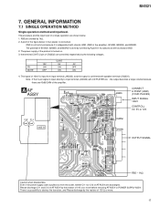
...) INPUT SIGNAL 10mV CONTROLL 0V, 5V or 12V SIDE B OUTPUT SIGNAL R85 - 1kΩ Caution when disassemble. Note : If the music signal is connected. There is done by the resistor of 100 Ω or more before removing AF ASSY or POWER SUPPLY ASSY. RY MUTE 12V ON OFF CONT 5V ON ON 0V OFF ON 4. M-IS21 7. The procedure and the input level...
...) INPUT SIGNAL 10mV CONTROLL 0V, 5V or 12V SIDE B OUTPUT SIGNAL R85 - 1kΩ Caution when disassemble. Note : If the music signal is connected. There is done by the resistor of 100 Ω or more before removing AF ASSY or POWER SUPPLY ASSY. RY MUTE 12V ON OFF CONT 5V ON ON 0V OFF ON 4. M-IS21 7. The procedure and the input level...
Service Manual
Page 18
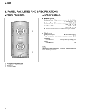
PANEL FACILITIES AND SPECIFICATIONS ¶ PANEL FACILITIES ¶ SPECIFICATIONS 7 Amplifier Section Continuous Power (RMS 100 W + 100 Wz (1 kHz, THD 10%, 6 Ω) Continuous Power (DIN 65 W + 65 W (1 kHz, THD 1%, 6 Ω) Music Power (DIN 150 W + 150 W (1 kHz, THD 1%, 6 Ω) ¶ Above specifications are for when the power supply is 230 V. ¶ 7 Micellaneous Power Requirements AC220-230 V, 50/60 Hz Power Consumption 120 W Power Consumption in standby mode 1 W Dimensions: Power Amplifier 150...
PANEL FACILITIES AND SPECIFICATIONS ¶ PANEL FACILITIES ¶ SPECIFICATIONS 7 Amplifier Section Continuous Power (RMS 100 W + 100 Wz (1 kHz, THD 10%, 6 Ω) Continuous Power (DIN 65 W + 65 W (1 kHz, THD 1%, 6 Ω) Music Power (DIN 150 W + 150 W (1 kHz, THD 1%, 6 Ω) ¶ Above specifications are for when the power supply is 230 V. ¶ 7 Micellaneous Power Requirements AC220-230 V, 50/60 Hz Power Consumption 120 W Power Consumption in standby mode 1 W Dimensions: Power Amplifier 150...


