Service Manual
Page 5
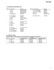
... ES are constructed the same except for the following: Part No. Description GM-X552/X1R/UC GM-X552/X1R/EW GM-X552/X1R/ES 9 Panel HNB0124 HNB0141 HNB0124 11 Panel HNB0137 HNB0145 HNB0137 13 Heat Sink HNR0180 HNR0188 HNR0180 16 Amp Unit HWH0142 HWH0141 HWH0143 5 GM-X552 (1) EXTERIOR SECTION PARTS LIST Mark No. BBZ30P050FMC BBZ30P060FMC BBZ30P080FMC BSZ30P050FZK CBA1323 6 Screw...
... ES are constructed the same except for the following: Part No. Description GM-X552/X1R/UC GM-X552/X1R/EW GM-X552/X1R/ES 9 Panel HNB0124 HNB0141 HNB0124 11 Panel HNB0137 HNB0145 HNB0137 13 Heat Sink HNR0180 HNR0188 HNR0180 16 Amp Unit HWH0142 HWH0141 HWH0143 5 GM-X552 (1) EXTERIOR SECTION PARTS LIST Mark No. BBZ30P050FMC BBZ30P060FMC BBZ30P080FMC BSZ30P050FZK CBA1323 6 Screw...
Service Manual
Page 6
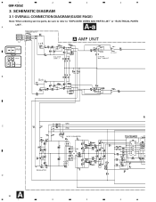
1 2 3 4 GM-X552 3. A A-a SPEAKER INPUT L+ R+ L- A AMP UNIT Large size A-a A-b SCH diagram A-a A-b Guide page A-a A-b Detailed page ISOLATOR GAIN = 1 LPF SELECT LP FILTER 80Hz - 12dB/OCT B C DC/DC CONVERTER REGULATOR D A 6 1 2 3 BFC (EW,ES mo 4 SCHEMATIC DIAGRAM 3.1 OVERALL CONNECTION DIAGRAM(GUIDE PAGE) Note: When ordering service parts, be sure to refer to "EXPLODED VIEWS AND PARTS LIST" or "ELECTRICAL PARTS LIST". R-
1 2 3 4 GM-X552 3. A A-a SPEAKER INPUT L+ R+ L- A AMP UNIT Large size A-a A-b SCH diagram A-a A-b Guide page A-a A-b Detailed page ISOLATOR GAIN = 1 LPF SELECT LP FILTER 80Hz - 12dB/OCT B C DC/DC CONVERTER REGULATOR D A 6 1 2 3 BFC (EW,ES mo 4 SCHEMATIC DIAGRAM 3.1 OVERALL CONNECTION DIAGRAM(GUIDE PAGE) Note: When ordering service parts, be sure to refer to "EXPLODED VIEWS AND PARTS LIST" or "ELECTRICAL PARTS LIST". R-
Service Manual
Page 8
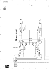
SPEAKER INPUT ISOLATOR GAIN = 1 A AMP UNIT LPF SELECT LP FILTER 80Hz - 12dB/OCT C B A A-a A-b 1 2 3 GM-X552 4 3 2 1 4 3 2 1 8 A-a D L+ R+ L- R-
SPEAKER INPUT ISOLATOR GAIN = 1 A AMP UNIT LPF SELECT LP FILTER 80Hz - 12dB/OCT C B A A-a A-b 1 2 3 GM-X552 4 3 2 1 4 3 2 1 8 A-a D L+ R+ L- R-
Service Manual
Page 12
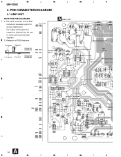
INPUT LR C GAIN LPF D A 12 1 2 3 4 For further information for several destination. The parts mounted on this PCB include all necessary parts for respective destinations, be sure to check with the schematic diagram. 2. Viewpoint of PCB diagrams A AMP UNIT Connector Capacitor SIDE A P.C.Board Chip Part B SIDE B SPEAKER R+ RINPUT L+ L- PCB CONNECTION DIAGRAM 4.1 AMP UNIT NOTE FOR PCB DIAGRAMS A 1. 1 2 3 4 GM-X552 4.
INPUT LR C GAIN LPF D A 12 1 2 3 4 For further information for several destination. The parts mounted on this PCB include all necessary parts for respective destinations, be sure to check with the schematic diagram. 2. Viewpoint of PCB diagrams A AMP UNIT Connector Capacitor SIDE A P.C.Board Chip Part B SIDE B SPEAKER R+ RINPUT L+ L- PCB CONNECTION DIAGRAM 4.1 AMP UNIT NOTE FOR PCB DIAGRAMS A 1. 1 2 3 4 GM-X552 4.
Service Manual
Page 16
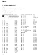
.../__S___J Chip Capacitor (except for CQS.....) CKS....., CCS....., CSZS..... =====Circuit Symbol and No.===Part Name Part No A Unit Number : HWH0142(GM-X552/X1R/UC) : HWH0141(GM-X552/X1R/EW) : HWH0143(GM-X552/X1R/ES) Unit Name : Amp Unit MISCELLANEOUS IC 101 IC IC 651 IC IC 851 IC IC 852 IC IC 901 IC NJM4558L PA2027A NJM2068D.../4PU681J RD1/4PU681J RD1/4PU511J RD1/4PU511J RD1/4PU333J RD1/4PU333J RD1/4PU681J RD1/4PU681J RD1/4PU223J RD1/4PU223J RD1/4PU101J ELECTRICAL PARTS LIST NOTE: - GM-X552 5. Parts whose parts numbers are omitted are subject to being not supplied. -
.../__S___J Chip Capacitor (except for CQS.....) CKS....., CCS....., CSZS..... =====Circuit Symbol and No.===Part Name Part No A Unit Number : HWH0142(GM-X552/X1R/UC) : HWH0141(GM-X552/X1R/EW) : HWH0143(GM-X552/X1R/ES) Unit Name : Amp Unit MISCELLANEOUS IC 101 IC IC 651 IC IC 851 IC IC 852 IC IC 901 IC NJM4558L PA2027A NJM2068D.../4PU681J RD1/4PU681J RD1/4PU511J RD1/4PU511J RD1/4PU333J RD1/4PU333J RD1/4PU681J RD1/4PU681J RD1/4PU223J RD1/4PU223J RD1/4PU101J ELECTRICAL PARTS LIST NOTE: - GM-X552 5. Parts whose parts numbers are omitted are subject to being not supplied. -
Service Manual
Page 19
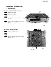
GENERAL INFORMATION 7.1 DISASSEMBLY - Remove the twelve screws and then remove the Amp Unit. GM-X552 Case Panel Fig.1 Amp Unit Fig.2 19 7. Remove the two screws. Remove the three screws and then remove the Case. Removing the Case and the Panel (Fig.1) Remove the four screws. Removing the Amp Unit (Fig.2) Remove the fourteen screws. Remove the six screws and then remove the Panel. - Remove the screw.
GENERAL INFORMATION 7.1 DISASSEMBLY - Remove the twelve screws and then remove the Amp Unit. GM-X552 Case Panel Fig.1 Amp Unit Fig.2 19 7. Remove the two screws. Remove the three screws and then remove the Case. Removing the Case and the Panel (Fig.1) Remove the four screws. Removing the Amp Unit (Fig.2) Remove the fourteen screws. Remove the six screws and then remove the Panel. - Remove the screw.


