Service Manual
Page 1
Service GM-X552/X1R/EW Manual BRIDGEABLE POWER AMPLIFIER GM-X552 GM-X552 X1R/EW GM-X552 X1R/ES ORDER NO. CRT2616 X1R/UC CONTENTS 1. OPERATIONS AND SPECIFICATIONS 20 PIONEER CORPORATION 4-1, Meguro 1-Chome, Meguro-ku, Tokyo 153-8654, Japan PIONEER ELECTRONICS SERVICE INC. P.O.Box 1760, Long Beach, CA 90801-1760 U.S.A. NOV. 2000 Printed in Japan PIONEER EUROPE N.V. PCB CONNECTION DIAGRAM 12 5. ADJUSTMENT 18 7. SAFETY INFORMATION 2 2. GENERAL INFORMATION 19 7.1 DISASSEMBLY 19 8. SCHEMATIC DIAGRAM 6 4. ELECTRICAL PARTS LIST 16...
Service GM-X552/X1R/EW Manual BRIDGEABLE POWER AMPLIFIER GM-X552 GM-X552 X1R/EW GM-X552 X1R/ES ORDER NO. CRT2616 X1R/UC CONTENTS 1. OPERATIONS AND SPECIFICATIONS 20 PIONEER CORPORATION 4-1, Meguro 1-Chome, Meguro-ku, Tokyo 153-8654, Japan PIONEER ELECTRONICS SERVICE INC. P.O.Box 1760, Long Beach, CA 90801-1760 U.S.A. NOV. 2000 Printed in Japan PIONEER EUROPE N.V. PCB CONNECTION DIAGRAM 12 5. ADJUSTMENT 18 7. SAFETY INFORMATION 2 2. GENERAL INFORMATION 19 7.1 DISASSEMBLY 19 8. SCHEMATIC DIAGRAM 6 4. ELECTRICAL PARTS LIST 16...
Service Manual
Page 2
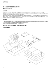
... and refer the repair to a qualified service technician. EXPLODED VIEWS AND PARTS LIST 2.1 PACKING 2 GM-X552 1. GM-X552/X1R/UC CAUTION This service manual is not meant for qualified service technicians; Improperly performed repairs can adversely affect the safety and reliability of this manual. If you should not risk trying to cause cancer, birth defects or other reproductive harm. Health & Safety Code Section 25249...
... and refer the repair to a qualified service technician. EXPLODED VIEWS AND PARTS LIST 2.1 PACKING 2 GM-X552 1. GM-X552/X1R/UC CAUTION This service manual is not meant for qualified service technicians; Improperly performed repairs can adversely affect the safety and reliability of this manual. If you should not risk trying to cause cancer, birth defects or other reproductive harm. Health & Safety Code Section 25249...
Service Manual
Page 3
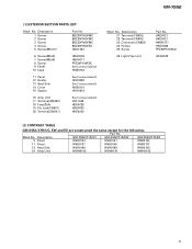
... HDE0036 HNS0101 - Owner's Manual Model GM-X552/X1R/UC GM-X552/X1R/EW GM-X552/X1R/ES Part No. HRD0165 HRD0157 HRD0166 HRD0172 Language English, French English, Spanish, German, French, Italian, Dutch English, Spanish Portuguese(B), Arabic 3 GM-X552 NOTE: - Parts marked by "*" are generally unavailable because they are used for disassembly. - Screws adjacent to ∇ mark on the product are not in our Master Spare Parts List. -
... HDE0036 HNS0101 - Owner's Manual Model GM-X552/X1R/UC GM-X552/X1R/EW GM-X552/X1R/ES Part No. HRD0165 HRD0157 HRD0166 HRD0172 Language English, French English, Spanish, German, French, Italian, Dutch English, Spanish Portuguese(B), Arabic 3 GM-X552 NOTE: - Parts marked by "*" are generally unavailable because they are used for disassembly. - Screws adjacent to ∇ mark on the product are not in our Master Spare Parts List. -
Service Manual
Page 5
...: Part No. GM-X552 (1) EXTERIOR SECTION PARTS LIST Mark No. Description 1 Screw 2 Screw 3 Screw 4 Screw 5 Screw(M3x12) Part No. BBZ30P050FMC BBZ30P060FMC BBZ30P080FMC BSZ30P050FZK CBA1323 6 Screw(M3x5) 7 Screw(M3x8) 8 Screw 9 Panel 10 Case HBA0006 HBA0011 PPZ30P100FZK See Contrast table(2) HNB0133 11 Panel 12 Holder 13 Heat Sink 14 Cover 15 Spacer See Contrast table(2) HNC0080 See Contrast table(2) HNS0101 HNV0016 16 Amp Unit 17 Terminal(CN999) 18 Fuse(25A...
...: Part No. GM-X552 (1) EXTERIOR SECTION PARTS LIST Mark No. Description 1 Screw 2 Screw 3 Screw 4 Screw 5 Screw(M3x12) Part No. BBZ30P050FMC BBZ30P060FMC BBZ30P080FMC BSZ30P050FZK CBA1323 6 Screw(M3x5) 7 Screw(M3x8) 8 Screw 9 Panel 10 Case HBA0006 HBA0011 PPZ30P100FZK See Contrast table(2) HNB0133 11 Panel 12 Holder 13 Heat Sink 14 Cover 15 Spacer See Contrast table(2) HNC0080 See Contrast table(2) HNS0101 HNV0016 16 Amp Unit 17 Terminal(CN999) 18 Fuse(25A...
Service Manual
Page 6
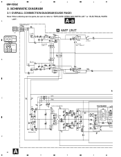
R- A A-a SPEAKER INPUT L+ R+ L- A AMP UNIT Large size A-a A-b SCH diagram A-a A-b Guide page A-a A-b Detailed page ISOLATOR GAIN = 1 LPF SELECT LP FILTER 80Hz - 12dB/OCT B C DC/DC CONVERTER REGULATOR D A 6 1 2 3 BFC (EW,ES mo 4 1 2 3 4 GM-X552 3. SCHEMATIC DIAGRAM 3.1 OVERALL CONNECTION DIAGRAM(GUIDE PAGE) Note: When ordering service parts, be sure to refer to "EXPLODED VIEWS AND PARTS LIST" or "ELECTRICAL PARTS LIST".
R- A A-a SPEAKER INPUT L+ R+ L- A AMP UNIT Large size A-a A-b SCH diagram A-a A-b Guide page A-a A-b Detailed page ISOLATOR GAIN = 1 LPF SELECT LP FILTER 80Hz - 12dB/OCT B C DC/DC CONVERTER REGULATOR D A 6 1 2 3 BFC (EW,ES mo 4 1 2 3 4 GM-X552 3. SCHEMATIC DIAGRAM 3.1 OVERALL CONNECTION DIAGRAM(GUIDE PAGE) Note: When ordering service parts, be sure to refer to "EXPLODED VIEWS AND PARTS LIST" or "ELECTRICAL PARTS LIST".
Service Manual
Page 8
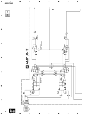
SPEAKER INPUT ISOLATOR GAIN = 1 A AMP UNIT LPF SELECT LP FILTER 80Hz - 12dB/OCT C B A A-a A-b 1 2 3 GM-X552 4 3 2 1 R- 4 3 2 1 8 A-a D L+ R+ L-
SPEAKER INPUT ISOLATOR GAIN = 1 A AMP UNIT LPF SELECT LP FILTER 80Hz - 12dB/OCT C B A A-a A-b 1 2 3 GM-X552 4 3 2 1 R- 4 3 2 1 8 A-a D L+ R+ L-
Service Manual
Page 12
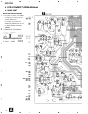
For further information for several destination. The parts mounted on this PCB include all necessary parts for respective destinations, be sure to check with the schematic diagram. 2. INPUT LR C GAIN LPF D A 12 1 2 3 4 Viewpoint of PCB diagrams A AMP UNIT Connector Capacitor SIDE A P.C.Board Chip Part B SIDE B SPEAKER R+ RINPUT L+ L- 1 2 3 4 GM-X552 4. PCB CONNECTION DIAGRAM 4.1 AMP UNIT NOTE FOR PCB DIAGRAMS A 1.
For further information for several destination. The parts mounted on this PCB include all necessary parts for respective destinations, be sure to check with the schematic diagram. 2. INPUT LR C GAIN LPF D A 12 1 2 3 4 Viewpoint of PCB diagrams A AMP UNIT Connector Capacitor SIDE A P.C.Board Chip Part B SIDE B SPEAKER R+ RINPUT L+ L- 1 2 3 4 GM-X552 4. PCB CONNECTION DIAGRAM 4.1 AMP UNIT NOTE FOR PCB DIAGRAMS A 1.
Service Manual
Page 16
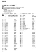
...PARTS LIST NOTE: - The part numbers shown below indicate chip components. GM-X552 5. Parts whose parts numbers are omitted are subject to being not supplied. - Chip Resistor RS1/_S___J,RS1/__S___J Chip Capacitor (except for CQS.....) CKS....., CCS....., CSZS..... =====Circuit Symbol and No.===Part Name Part No A Unit Number : HWH0142(GM-X552/X1R/UC) : HWH0141(GM-X552/X1R/EW) : HWH0143(GM-X552/X1R/ES) Unit Name : Amp Unit... Thermistor TH 903 S 101 S 901 VR 453 Thermistor Switch(LPF SELECT) Switch(BFC)(EW,ES model) Volume 10kΩ(A) Fuse 25A RESISTORS R 123 R 124 R 203 R 204 ...
...PARTS LIST NOTE: - The part numbers shown below indicate chip components. GM-X552 5. Parts whose parts numbers are omitted are subject to being not supplied. - Chip Resistor RS1/_S___J,RS1/__S___J Chip Capacitor (except for CQS.....) CKS....., CCS....., CSZS..... =====Circuit Symbol and No.===Part Name Part No A Unit Number : HWH0142(GM-X552/X1R/UC) : HWH0141(GM-X552/X1R/EW) : HWH0143(GM-X552/X1R/ES) Unit Name : Amp Unit... Thermistor TH 903 S 101 S 901 VR 453 Thermistor Switch(LPF SELECT) Switch(BFC)(EW,ES model) Volume 10kΩ(A) Fuse 25A RESISTORS R 123 R 124 R 203 R 204 ...
Service Manual
Page 18
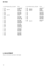
ADJUSTMENT There is no information to be shown in this chapter. 18 GM-X552 =====Circuit Symbol and No.===Part Name C 573 C 574 C 651 220µF/10V C 652 C 653 C 654 C 655 C 656 C 658 C 659 470µF/16V C 661 C 662 C 671 C 851 C 852 C 853 C 854 C 859 C... 860 C 866 C 867 C 868 C 869 C 870 C 871 C 872 C 873 C 876 C 877 C 878 C 879 C 902 C 903 C 904 C 905 Part No CCCCH330J100 CCCCH330J100...
ADJUSTMENT There is no information to be shown in this chapter. 18 GM-X552 =====Circuit Symbol and No.===Part Name C 573 C 574 C 651 220µF/10V C 652 C 653 C 654 C 655 C 656 C 658 C 659 470µF/16V C 661 C 662 C 671 C 851 C 852 C 853 C 854 C 859 C... 860 C 866 C 867 C 868 C 869 C 870 C 871 C 872 C 873 C 876 C 877 C 878 C 879 C 902 C 903 C 904 C 905 Part No CCCCH330J100 CCCCH330J100...
Service Manual
Page 19
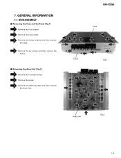
7. GENERAL INFORMATION 7.1 DISASSEMBLY - Remove the two screws. Removing the Amp Unit (Fig.2) Remove the fourteen screws. Removing the Case and the Panel (Fig.1) Remove the four screws. GM-X552 Case Panel Fig.1 Amp Unit Fig.2 19 Remove the three screws and then remove the Case. Remove the six screws and then remove the Panel. - Remove the twelve screws and then remove the Amp Unit. Remove the screw.
7. GENERAL INFORMATION 7.1 DISASSEMBLY - Remove the two screws. Removing the Amp Unit (Fig.2) Remove the fourteen screws. Removing the Case and the Panel (Fig.1) Remove the four screws. GM-X552 Case Panel Fig.1 Amp Unit Fig.2 19 Remove the three screws and then remove the Case. Remove the six screws and then remove the Panel. - Remove the twelve screws and then remove the Amp Unit. Remove the screw.
Service Manual
Page 20
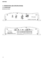
GM-X552/X1R/EW 20 GM-X552 8. OPERATIONS AND SPECIFICATIONS 8.1 OPERATIONS -
GM-X552/X1R/EW 20 GM-X552 8. OPERATIONS AND SPECIFICATIONS 8.1 OPERATIONS -
Service Manual
Page 21
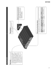
Power Indicator The power indicator lights when the power is turned up , turn gain control on . output of speaker that is connected to the speaker output connector and the car stereo system: LPF Select Switch LPF (left) OFF (right) Audio frequency range to an MW/LW broadcast with your car stereo, change the BFC switch using with max. GM-X552 21 Setting the Unit Gain Control If the sound level is too low, even when the volume of the car stereo used along with this power amplifier is turned up , turn the gain control counter-clockwise. When...
Power Indicator The power indicator lights when the power is turned up , turn gain control on . output of speaker that is connected to the speaker output connector and the car stereo system: LPF Select Switch LPF (left) OFF (right) Audio frequency range to an MW/LW broadcast with your car stereo, change the BFC switch using with max. GM-X552 21 Setting the Unit Gain Control If the sound level is too low, even when the volume of the car stereo used along with this power amplifier is turned up , turn the gain control counter-clockwise. When...
Service Manual
Page 22
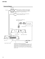
... terminal of this wire to the system remote control terminal of the battery. Front side Connecting wires with RCA output jacks External Output RCA input jack Speaker input terminal Fuse (25 A) Speaker output terminal Back side System remote control wire (sold separately). Ground wire (black) [RD-223] (sold separately) After making all other connections at the amplifier, connect the battery wire terminal of the amplifier to the positive (+) terminal of the car stereo (SYSTEM REMOTE CONTROL). GM-X552 Connection Diagram Fuse (30 A) Grommet Fuse (30 A) Special red battery wire...
... terminal of this wire to the system remote control terminal of the battery. Front side Connecting wires with RCA output jacks External Output RCA input jack Speaker input terminal Fuse (25 A) Speaker output terminal Back side System remote control wire (sold separately). Ground wire (black) [RD-223] (sold separately) After making all other connections at the amplifier, connect the battery wire terminal of the amplifier to the positive (+) terminal of the car stereo (SYSTEM REMOTE CONTROL). GM-X552 Connection Diagram Fuse (30 A) Grommet Fuse (30 A) Special red battery wire...
Service Manual
Page 23
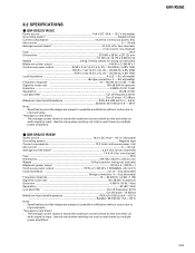
... input. Use this unit when an audio signal is input. GM-X552/X1R/EW Power source 14.4 V DC (10.8 - 15.1 V allowable) Grounding system ...Negative type Current consumption 13.2 A (at continuous power, 4 Ω) Idle current ...5 - 30 mA Average current drawn 4.4 A (4 Ω for two channels) ...7.4 A (4 Ω for one channel) Fuse ...25 A Dimensions 279 (W) x 58 (H) x 237 (D) mm 11 (W) x 2-1/4 (H) x 9-3/8 (D) in] Weight 3.6 kg (7.9 lbs) (Leads for wiring not included) Maximum power output...
... input. Use this unit when an audio signal is input. GM-X552/X1R/EW Power source 14.4 V DC (10.8 - 15.1 V allowable) Grounding system ...Negative type Current consumption 13.2 A (at continuous power, 4 Ω) Idle current ...5 - 30 mA Average current drawn 4.4 A (4 Ω for two channels) ...7.4 A (4 Ω for one channel) Fuse ...25 A Dimensions 279 (W) x 58 (H) x 237 (D) mm 11 (W) x 2-1/4 (H) x 9-3/8 (D) in] Weight 3.6 kg (7.9 lbs) (Leads for wiring not included) Maximum power output...
Service Manual
Page 24
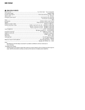
...; (2 - 8 Ω allowable) ...(Bridge connection: 4 - 8 Ω allowable) Frequency response 10 - 50,000 Hz (+0 dB, -1 dB) Signal-to-noise ratio ...100 dB (IEC-A network) Distortion ...0.008% (10 W, 1 kHz) Separation ...60 dB (1 kHz) Low pass filter ...Cut off frequency: 80 Hz ...Cut off slope: -12 dB/oct Maximum input level/impedance RCA: 6.5 V/22 kΩ (0.4 - 6.5 V) ...Speaker: 26 V/40 kΩ (1.6 - 26 V) Note: • Specifications and the design...
...; (2 - 8 Ω allowable) ...(Bridge connection: 4 - 8 Ω allowable) Frequency response 10 - 50,000 Hz (+0 dB, -1 dB) Signal-to-noise ratio ...100 dB (IEC-A network) Distortion ...0.008% (10 W, 1 kHz) Separation ...60 dB (1 kHz) Low pass filter ...Cut off frequency: 80 Hz ...Cut off slope: -12 dB/oct Maximum input level/impedance RCA: 6.5 V/22 kΩ (0.4 - 6.5 V) ...Speaker: 26 V/40 kΩ (1.6 - 26 V) Note: • Specifications and the design...


