
Owner's Manual
Page 1
... ground wire to excessive noise. BRIDGEABLE FOUR-CHANNEL POWER AMPLIFIER AMPLIFICATEUR DE PUISSANCE PONTABLE A QUATRE VOIES Owner's Manual GM-X364 Mode d'emploi PIONEER CORPORATION 4-1, MEGURO 1-CHOME, MEGURO-KU, TOKYO 153-8654, JAPAN PIONEER ELECTRONICS (USA) INC. P.O. C.P. 03100 TEL: 5-688-52-90 Published by Pioneer Corporation. Copyright © 2001 Pioneer Corporation. Before Using This Product Thank you for...
... ground wire to excessive noise. BRIDGEABLE FOUR-CHANNEL POWER AMPLIFIER AMPLIFICATEUR DE PUISSANCE PONTABLE A QUATRE VOIES Owner's Manual GM-X364 Mode d'emploi PIONEER CORPORATION 4-1, MEGURO 1-CHOME, MEGURO-KU, TOKYO 153-8654, JAPAN PIONEER ELECTRONICS (USA) INC. P.O. C.P. 03100 TEL: 5-688-52-90 Published by Pioneer Corporation. Copyright © 2001 Pioneer Corporation. Before Using This Product Thank you for...
Owner's Manual
Page 2
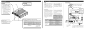
...unit. • Secure the wiring with RCA output jacks Front side Speaker input terminal See the "Using the Speaker Input" section. Amplifier with the standards listed below. When using the speaker input terminals, turn the gain control counter-clockwise. Connecting the Unit CAUTION •...8226; Make sure that have the same function. Otherwise the protection circuit may go dead if the engine is connected to the Pioneer amplifier. Install and route the separately sold separately) Connect the male terminal of the car stereo to the speaker output connector and ...
...unit. • Secure the wiring with RCA output jacks Front side Speaker input terminal See the "Using the Speaker Input" section. Amplifier with the standards listed below. When using the speaker input terminals, turn the gain control counter-clockwise. Connecting the Unit CAUTION •...8226; Make sure that have the same function. Otherwise the protection circuit may go dead if the engine is connected to the Pioneer amplifier. Install and route the separately sold separately) Connect the male terminal of the car stereo to the speaker output connector and ...
Owner's Manual
Page 3
... from the engine compartment to the interior of the vehicle. • After making all other connections to the amplifier, connect the battery wire terminal of the amplifier to speaker wire ends. GND terminal Power terminal System remote control terminal System remote control wire Ground wire Battery ...the speaker wires, passing them through the terminal cover. • Fix the speaker wires securely with the terminal screws. Attach lugs to the amplifier using the supplied speaker input connector. • Do not connect both the RCA input and the speaker input at the same time. 7 ...
... from the engine compartment to the interior of the vehicle. • After making all other connections to the amplifier, connect the battery wire terminal of the amplifier to speaker wire ends. GND terminal Power terminal System remote control terminal System remote control wire Ground wire Battery ...the speaker wires, passing them through the terminal cover. • Fix the speaker wires securely with the terminal screws. Attach lugs to the amplifier using the supplied speaker input connector. • Do not connect both the RCA input and the speaker input at the same time. 7 ...

Owner's Manual
Page 4
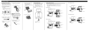
... The average current drawn is nearly the maximum current drawn by this value when working out total current drawn by multiple power amplifiers. This is important to prevent wires from damage. • Install tapping screws in the manner specified. Push on the screws...Power source ...14.4 V DC (10.8 - 15.1 V allowable) Grounding system ...Negative type Current consumption ...18.1 A (at the point marked, and install the amplifier, either on the chassis 1. Insert the supplied tapping screws (4 × 18 mm) into the screw holes. Drill 2.5 mm (1/8 inch) diameter holes at continuous...
... The average current drawn is nearly the maximum current drawn by this value when working out total current drawn by multiple power amplifiers. This is important to prevent wires from damage. • Install tapping screws in the manner specified. Push on the screws...Power source ...14.4 V DC (10.8 - 15.1 V allowable) Grounding system ...Negative type Current consumption ...18.1 A (at the point marked, and install the amplifier, either on the chassis 1. Insert the supplied tapping screws (4 × 18 mm) into the screw holes. Drill 2.5 mm (1/8 inch) diameter holes at continuous...

