
Service Manual
Page 5
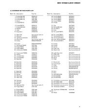
Description 46 Cord(CN502) 47 Cord(CN552) 48 Cord(CN854) 49 Cord(CN855) 50 Holder Part No. GM-X1024,GM-X924 (1) EXTERIOR SECTION PARTS LIST Mark No. HDE5501 HDE5501 HDE5501 HDE5501 HNC0029 51 Clip 52 Screw(M3×25) 53 Fan Motor 54 Fuse 55 ... HBA0006 6 Screw(M3×8) 7 Screw(M2.6×6) 8 Washer 9 Case 10 Separator HBA0011 HBA0012 HBF0005 HNB0036 HNM0046 11 Heat Sink 12 Window 13 Lighting Conductor 14 Amp Unit 15 Screw See Contrast table (2) HNS0053 HNV0012 See Contrast table (2) BMS30P060FZK 16 Screw 17 Terminal(CN905) 18 Plug(CN503) 19 Plug(CN553) 20 Connector...
Description 46 Cord(CN502) 47 Cord(CN552) 48 Cord(CN854) 49 Cord(CN855) 50 Holder Part No. GM-X1024,GM-X924 (1) EXTERIOR SECTION PARTS LIST Mark No. HDE5501 HDE5501 HDE5501 HDE5501 HNC0029 51 Clip 52 Screw(M3×25) 53 Fan Motor 54 Fuse 55 ... HBA0006 6 Screw(M3×8) 7 Screw(M2.6×6) 8 Washer 9 Case 10 Separator HBA0011 HBA0012 HBF0005 HNB0036 HNM0046 11 Heat Sink 12 Window 13 Lighting Conductor 14 Amp Unit 15 Screw See Contrast table (2) HNS0053 HNV0012 See Contrast table (2) BMS30P060FZK 16 Screw 17 Terminal(CN905) 18 Plug(CN503) 19 Plug(CN553) 20 Connector...
Service Manual
Page 6
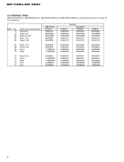
... CNM5856 CNM5853 HXA0247 HNB0043 HNS0046 CNM5949 CNM5948 HXA0247 HNB0043 HNS0046 CNM5949 CNM5948 HXA0247 HNB0043 HNS0046 CNM5949 CNM5948 6 GM-X1024,GM-X924 (2) CONTRAST TABLE GM-X1024/X1R/UC, GM-X924/X1R/UC, GM-X924/X1R/EW and GM-X924/X1R/ES are constructed the same except for the following: Mark No. 11 14 39 64 ...65 Symbol and Description Heat Sink Amp Unit Network Unit Plate Unit Sheet Unit GM-X1024 X1R/UC HNR0073 HWH0066...
... CNM5856 CNM5853 HXA0247 HNB0043 HNS0046 CNM5949 CNM5948 HXA0247 HNB0043 HNS0046 CNM5949 CNM5948 HXA0247 HNB0043 HNS0046 CNM5949 CNM5948 6 GM-X1024,GM-X924 (2) CONTRAST TABLE GM-X1024/X1R/UC, GM-X924/X1R/UC, GM-X924/X1R/EW and GM-X924/X1R/ES are constructed the same except for the following: Mark No. 11 14 39 64 ...65 Symbol and Description Heat Sink Amp Unit Network Unit Plate Unit Sheet Unit GM-X1024 X1R/UC HNR0073 HWH0066...
Service Manual
Page 14
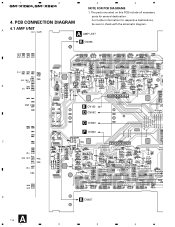
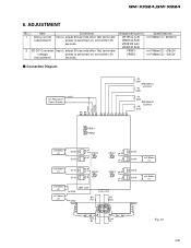
A 4.1 AMP UNIT A AMP UNIT B CN856 B C D A 14 1 OUTPUT INPUT 2CH/4CH B E CN102 D CN552 C CN502 F CN302 B CN857 2 3 A 4 PCB CONNECTION DIAGRAM For further information for several destination. 4. The parts mounted on this PCB include all necessary parts for respective destinations, be sure to check with the schematic diagram. 1 2 GM-X1024,GM-X924 3 4 NOTE FOR PCB DIAGRAMS 1.
A 4.1 AMP UNIT A AMP UNIT B CN856 B C D A 14 1 OUTPUT INPUT 2CH/4CH B E CN102 D CN552 C CN502 F CN302 B CN857 2 3 A 4 PCB CONNECTION DIAGRAM For further information for several destination. 4. The parts mounted on this PCB include all necessary parts for respective destinations, be sure to check with the schematic diagram. 1 2 GM-X1024,GM-X924 3 4 NOTE FOR PCB DIAGRAMS 1.
Service Manual
Page 24
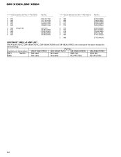
GM-X1024,GM-X924 =====Circuit Symbol and No.===Part Name C 957 C 959 C 960 C 961 C 962 C 963 4700µF/16V C 964 C 965 C 966 C 967 Part No CFTLA474J50 CFTLA104J50 CFTLA104J50 ... CEKA471M50 CEKA471M50 CQPA102J2A CFTLA104J50 CFTLA104J50 CONTRAST TABLE of AMP UNIT GM-X1024/X1R/UC, GM-X924/X1R/UC, GM-X924/X1R/EW and GM-X924/X1R/ES are constructed the same except for the following: Part No. Symbol and Description GM-X1024/X1R/UC GM-X924/X1R/UC GM-X924/X1R/EW GM-X924/X1R/ES S901 Switch Not used Not...
GM-X1024,GM-X924 =====Circuit Symbol and No.===Part Name C 957 C 959 C 960 C 961 C 962 C 963 4700µF/16V C 964 C 965 C 966 C 967 Part No CFTLA474J50 CFTLA104J50 CFTLA104J50 ... CEKA471M50 CEKA471M50 CQPA102J2A CFTLA104J50 CFTLA104J50 CONTRAST TABLE of AMP UNIT GM-X1024/X1R/UC, GM-X924/X1R/UC, GM-X924/X1R/EW and GM-X924/X1R/ES are constructed the same except for the following: Part No. Symbol and Description GM-X1024/X1R/UC GM-X924/X1R/UC GM-X924/X1R/EW GM-X924/X1R/ES S901 Switch Not used Not...
Service Manual
Page 25
...; (2W) SPEAKER B OUTPUT 4Ω (2W) POWER GND SYSTEM CONTROL VR951 VR952 mV Meter (1) Q215 Q216 E C VR201 E mV Meter (1) Q115 Q116 E C VR101 E C mV Meter + (3) mV Meter + (2) AMP UNIT GND BR GND 1kΩ VR401 E E VR301 E E Q415 Q416 mV Meter (1) Q315 Q316 mV Meter (1) AR 1kΩ 1kΩ 1kΩ BL AL...
...; (2W) SPEAKER B OUTPUT 4Ω (2W) POWER GND SYSTEM CONTROL VR951 VR952 mV Meter (1) Q215 Q216 E C VR201 E mV Meter (1) Q115 Q116 E C VR101 E C mV Meter + (3) mV Meter + (2) AMP UNIT GND BR GND 1kΩ VR401 E E VR301 E E Q415 Q416 mV Meter (1) Q315 Q316 mV Meter (1) AR 1kΩ 1kΩ 1kΩ BL AL...
Service Manual
Page 27
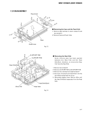
... B LPF/HPF PCB. 3. D B LPF/HPF PCB A LPF/HPF PCB F D F Heat Sink(Sub) F E E F F F E E F F Amp Unit Heat Sink(Sub) Heat Sink Fig. 14 - therefore, to remove the Amp Unit from the Heat Sink. 27 Remove eight screws A, seven screws B and two screws C. 2. GM-X1024,GM-X924 7.2 DISASSEMBLY A Panel Unit A A BB BB A B C B A A A BC Panel Unit A Case Fig. 13...
... B LPF/HPF PCB. 3. D B LPF/HPF PCB A LPF/HPF PCB F D F Heat Sink(Sub) F E E F F F E E F F Amp Unit Heat Sink(Sub) Heat Sink Fig. 14 - therefore, to remove the Amp Unit from the Heat Sink. 27 Remove eight screws A, seven screws B and two screws C. 2. GM-X1024,GM-X924 7.2 DISASSEMBLY A Panel Unit A A BB BB A B C B A A A BC Panel Unit A Case Fig. 13...


