Owner's Manual
Page 3
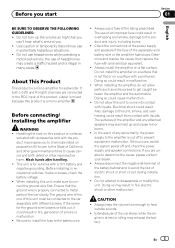
.... En 3 Use caution or temporarily discontinue use of this occurs, switch the system power off to prevent equipment malfunction. Before connecting/ installing the amplifier WARNING ! Wash hands after handling. ! If the screw for the ground wire loosens or falls out, it could result from contact with the ... allow parts such as - This unit is not flat or on this unit to come into contact with different screws. Do not install the amplifier on a surface that you can't hear what's around you to chemicals listed on a flat surface. If you start Section 01 English BE ...
.... En 3 Use caution or temporarily discontinue use of this occurs, switch the system power off to prevent equipment malfunction. Before connecting/ installing the amplifier WARNING ! Wash hands after handling. ! If the screw for the ground wire loosens or falls out, it could result from contact with the ... allow parts such as - This unit is not flat or on this unit to come into contact with different screws. Do not install the amplifier on a surface that you can't hear what's around you to chemicals listed on a flat surface. If you start Section 01 English BE ...
Owner's Manual
Page 4
... POWER/PROTECT indicator will turn red and the amplifier will operate to the amplifier; 1: a subwoofer with a 300 W (GMD8601) / 500 W (GM-D9601) or larger nominal input and an impedance 4 W, 2: a subwoofer with a 500 W (GM-D8601) / 800 W (GM-D9601) or larger nominal input and an impedance 2 W or 3: a subwoofer with a 800 W (GM-D8601) / 1 200 W (GM-D9601) or larger nominal input and an impedance...
... POWER/PROTECT indicator will turn red and the amplifier will operate to the amplifier; 1: a subwoofer with a 300 W (GMD8601) / 500 W (GM-D9601) or larger nominal input and an impedance 4 W, 2: a subwoofer with a 500 W (GM-D8601) / 800 W (GM-D9601) or larger nominal input and an impedance 2 W or 3: a subwoofer with a 800 W (GM-D8601) / 1 200 W (GM-D9601) or larger nominal input and an impedance...
Owner's Manual
Page 5
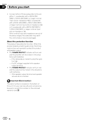
For use with an RCA equipped Pioneer car stereo, with maximum output of connecting the bass boost remote control to the amplifier, see the Connection diagram on the main unit, you hear too much noise when using the speaker input terminals, turn the gain control to ...outputting high volume sound etc., this function cuts off frequency from 0 dB to 18 dB. Setting the unit Section 02 English What's what GM-D8601 Front side 1 23 4 Rear side GM-D9601 Front side 1 23 4 Rear side stereo volume is turned up, turn these controls to excessive output, improper use or improper connection...
For use with an RCA equipped Pioneer car stereo, with maximum output of connecting the bass boost remote control to the amplifier, see the Connection diagram on the main unit, you hear too much noise when using the speaker input terminals, turn the gain control to ...outputting high volume sound etc., this function cuts off frequency from 0 dB to 18 dB. Setting the unit Section 02 English What's what GM-D8601 Front side 1 23 4 Rear side GM-D9601 Front side 1 23 4 Rear side stereo volume is turned up, turn these controls to excessive output, improper use or improper connection...
Owner's Manual
Page 6
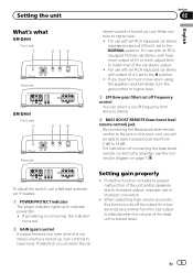
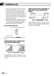
...and gain settings, the unit sound still cuts out periodically. To ensure continuous sound output with the head unit at high volume using amplifier gain control Signal waveform distorted with little increase in sound output may indicate improper setting of the gain control. Preout level: 4 V... Above illustration shows NORMAL gain setting. In such cases, please contact the nearest authorized Pioneer Service Station. Gain control of this will simply increase distortion, with high output, if you raise the gain of the head unit, ...
...and gain settings, the unit sound still cuts out periodically. To ensure continuous sound output with the head unit at high volume using amplifier gain control Signal waveform distorted with little increase in sound output may indicate improper setting of the gain control. Preout level: 4 V... Above illustration shows NORMAL gain setting. In such cases, please contact the nearest authorized Pioneer Service Station. Gain control of this will simply increase distortion, with high output, if you raise the gain of the head unit, ...
Owner's Manual
Page 7
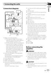
...positive + terminal of the battery. 2 Fuse 100 A (GM-D8601) / 150 A (GM-D9601) (sold separately) Each amplifier must be same size. parately) a Amplifier with RCA pin plugs (sold separately) The ground wires must be separately fused at 100 A (GM-D8601) / 150 A (GM-D9601). 3 Positive (+) terminal 4 Negative (*) terminal 5 ...- to the power terminal via the ignition switch. h Fuse 40 A × 2 (GM-D8601) / 40 A × 3 (GMD9601) i Front side j Rear side Before connecting the amplifier WARNING ! To protect the wiring, wrap sections in adhesive tape. ! Never cut the insulation...
...positive + terminal of the battery. 2 Fuse 100 A (GM-D8601) / 150 A (GM-D9601) (sold separately) Each amplifier must be same size. parately) a Amplifier with RCA pin plugs (sold separately) The ground wires must be separately fused at 100 A (GM-D8601) / 150 A (GM-D9601). 3 Positive (+) terminal 4 Negative (*) terminal 5 ...- to the power terminal via the ignition switch. h Fuse 40 A × 2 (GM-D8601) / 40 A × 3 (GMD9601) i Front side j Rear side Before connecting the amplifier WARNING ! To protect the wiring, wrap sections in adhesive tape. ! Never cut the insulation...
Owner's Manual
Page 8
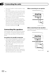
...if outputting high volume sound. Connect the speaker leads to suit the mode according to the power terminal via the ignition switch (12 V DC), the amplifier will remain on with the synthetic impedance less than 1 W, as possible from the antenna, antenna cable and tuner. Precautions for parallel connection ! When ... be set on or off, which may exhaust battery if the engine is canceled. When wiring two speakers in parallel, make sure that of the amplifier is the same as possible from 1 W to 8 W to one speaker. Turn down the volume until the mute function is at rest or idling. !...
...if outputting high volume sound. Connect the speaker leads to suit the mode according to the power terminal via the ignition switch (12 V DC), the amplifier will remain on with the synthetic impedance less than 1 W, as possible from the antenna, antenna cable and tuner. Precautions for parallel connection ! When ... be set on or off, which may exhaust battery if the engine is canceled. When wiring two speakers in parallel, make sure that of the amplifier is the same as possible from 1 W to 8 W to one speaker. Turn down the volume until the mute function is at rest or idling. !...
Owner's Manual
Page 9
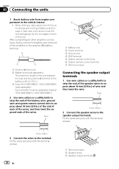
... jack of this unit Notes ! Since the wire will automatically turn on . Be careful to be connected together synchronously, connect the head unit and all amplifiers via the system remote control wire. ! The battery wire, the ground wire and the optional direct ground wire must be same size. ! Use a wire ..., including minor burns. ! Fasten while making sure to not to only turn on when the headunit is turned on the car stereo, not the amplifier. ! Connecting the units Section 03 English Connections when using the speaker input wire Connect the car stereo speaker output wires to this...
... jack of this unit Notes ! Since the wire will automatically turn on . Be careful to be connected together synchronously, connect the head unit and all amplifiers via the system remote control wire. ! The battery wire, the ground wire and the optional direct ground wire must be same size. ! Use a wire ..., including minor burns. ! Fasten while making sure to not to only turn on when the headunit is turned on the car stereo, not the amplifier. ! Connecting the units Section 03 English Connections when using the speaker input wire Connect the car stereo speaker output wires to this...
Owner's Manual
Page 10
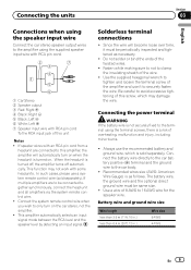
... the wire between the fuse and the positive + terminal of the battery is 30 cm (12 in.). 3 Fuse 100 A (GM-D8601) / 150 A (GM-D9601) (sold separately) Each amplifier must be separately fused at 100 A (GM-D8601) / 150 A (GM-D9601). 2 Use wire cutters or a utility knife to strip the end of the battery wire, ground wire and system...
... the wire between the fuse and the positive + terminal of the battery is 30 cm (12 in.). 3 Fuse 100 A (GM-D8601) / 150 A (GM-D9601) (sold separately) Each amplifier must be separately fused at 100 A (GM-D8601) / 150 A (GM-D9601). 2 Use wire cutters or a utility knife to strip the end of the battery wire, ground wire and system...
Owner's Manual
Page 11
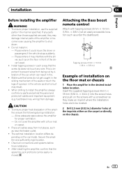
... optimal installation location differs de- Installation Section 04 English Before installing the amplifier WARNING ! If any wire. Places where it may damage internal parts of the amplifier, or become loose causing the amplifier to prevent wires from being cut by vibration of installation on the screws... result in .) diameter holes at a sufficiently rigid location. ! To ensure proper heat dissipation of the driver's seat. ! Do not cover the amplifier with tapping screws (3 mm × 10 mm (1/8 in. × 3/8 in front of the ampli- Place all connections and systems before final...
... optimal installation location differs de- Installation Section 04 English Before installing the amplifier WARNING ! If any wire. Places where it may damage internal parts of the amplifier, or become loose causing the amplifier to prevent wires from being cut by vibration of installation on the screws... result in .) diameter holes at a sufficiently rigid location. ! To ensure proper heat dissipation of the driver's seat. ! Do not cover the amplifier with tapping screws (3 mm × 10 mm (1/8 in. × 3/8 in front of the ampli- Place all connections and systems before final...
Owner's Manual
Page 12
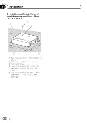
Section 04 Installation 3 Install the amplifier with the use of supplied tapping screws (4 mm × 18 mm ( 5/32 in. × 3/4 in.)). 1 3 2 4 5 1 Tapping-screws (4 mm × 18 mm (5/32 in. × 3/4 in.)) 2 Drill a 2.5 mm (3/32 in.) diameter hole. 3 Floor mat or chassis 4 Hole-to-hole distance: 257 mm (10-1/8 in.) (GM-D8601) / 307 mm (12-1/8 in.) (GMD9601) 5 Hole-to-hole distance: 181 mm (7-1/8 in.) (GM-D8601) / 181 mm (7-1/8 in.) (GMD9601) 12 En
Section 04 Installation 3 Install the amplifier with the use of supplied tapping screws (4 mm × 18 mm ( 5/32 in. × 3/4 in.)). 1 3 2 4 5 1 Tapping-screws (4 mm × 18 mm (5/32 in. × 3/4 in.)) 2 Drill a 2.5 mm (3/32 in.) diameter hole. 3 Floor mat or chassis 4 Hole-to-hole distance: 257 mm (10-1/8 in.) (GM-D8601) / 307 mm (12-1/8 in.) (GMD9601) 5 Hole-to-hole distance: 181 mm (7-1/8 in.) (GM-D8601) / 181 mm (7-1/8 in.) (GMD9601) 12 En
Owner's Manual
Page 14
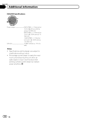
The average current drawn is input. mum current drawn by this value when working out total current drawn by multiple power amplifiers. 14 En Specifications and the design are subject to 240 Hz and ≦ 1 % THD+N) 800 W RMS × 1 Channel (at 14.4 V, 2 W, 100 Hz and ≦ 1 % THD+N) 1 ...
The average current drawn is input. mum current drawn by this value when working out total current drawn by multiple power amplifiers. 14 En Specifications and the design are subject to 240 Hz and ≦ 1 % THD+N) 800 W RMS × 1 Channel (at 14.4 V, 2 W, 100 Hz and ≦ 1 % THD+N) 1 ...

