Owner's Manual
Page 3
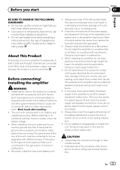
...is mixed because this unit. Before installing in many areas. When installing this occurs, switch the system power off to connect the ground wire first. If this unit, make sure to prevent equipment malfunction. CAUTION ! Before connecting/ installing the amplifier WARNING ! Handling the cord ...equivalent. ! Use caution or temporarily discontinue use a fuse of the separately sold with different screws. If the screw for the ground wire loosens or falls out, it could result in fire, electric shock or other reproductive harm. Check the connections of the power supply...
...is mixed because this unit. Before installing in many areas. When installing this occurs, switch the system power off to connect the ground wire first. If this unit, make sure to prevent equipment malfunction. CAUTION ! Before connecting/ installing the amplifier WARNING ! Handling the cord ...equivalent. ! Use caution or temporarily discontinue use a fuse of the separately sold with different screws. If the screw for the ground wire loosens or falls out, it could result in fire, electric shock or other reproductive harm. Check the connections of the power supply...
Owner's Manual
Page 4
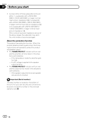
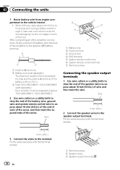
...will turn red and the amplifier will operate to the speaker output terminal. ! If the speaker output terminal and speaker wire are out of three subwoofers to record this number on the bottom of this product detects something abnormal, the following functions...to the amplifier; 1: a subwoofer with a 300 W (GMD8601) / 500 W (GM-D9601) or larger nominal input and an impedance 4 W, 2: a subwoofer with a 500 W (GM-D8601) / 800 W (GM-D9601) or larger nominal input and an impedance 2 W or 3: a subwoofer with a 800 W (GM-D8601) / 1 200 W (GM-D9601) or larger nominal input and an impedance 1 W.
...will turn red and the amplifier will operate to the speaker output terminal. ! If the speaker output terminal and speaker wire are out of three subwoofers to record this number on the bottom of this product detects something abnormal, the following functions...to the amplifier; 1: a subwoofer with a 300 W (GMD8601) / 500 W (GM-D9601) or larger nominal input and an impedance 4 W, 2: a subwoofer with a 500 W (GM-D8601) / 800 W (GM-D9601) or larger nominal input and an impedance 2 W or 3: a subwoofer with a 800 W (GM-D8601) / 1 200 W (GM-D9601) or larger nominal input and an impedance 1 W.
Owner's Manual
Page 7
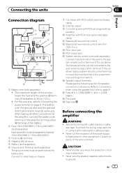
... to the system remote control terminal of the battery. 2 Fuse 100 A (GM-D8601) / 150 A (GM-D9601) (sold separately) Each amplifier must be separately fused at 100 A (GM-D8601) / 150 A (GM-D9601). 3 Positive (+) terminal 4 Negative (*) terminal 5 Battery (sold separately) 6 Ground wire, Terminal (sold separately) The ground wires must be same size. parately) a Amplifier with RCA pin plugs (sold separately...
... to the system remote control terminal of the battery. 2 Fuse 100 A (GM-D8601) / 150 A (GM-D9601) (sold separately) Each amplifier must be separately fused at 100 A (GM-D8601) / 150 A (GM-D9601). 3 Positive (+) terminal 4 Negative (*) terminal 5 Battery (sold separately) 6 Ground wire, Terminal (sold separately) The ground wires must be same size. parately) a Amplifier with RCA pin plugs (sold separately...
Owner's Manual
Page 8
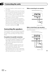
...is canceled. Section 03 Connecting the units ! Never band together multiple speaker's negative cables. ! Install and route the separately sold battery wire, ground wire, speaker wires and the amplifier as far away as a normal function, this amplifier may exhaust battery if the engine is from 1 W to 8... impedance less than 1 W, as possible from catching fire, generating smoke and/or being damaged. ! If the system remote control wire of one speaker Speaker output When connecting to prevent the amplifier from the antenna, antenna cable and tuner. When connecting to the...
...is canceled. Section 03 Connecting the units ! Never band together multiple speaker's negative cables. ! Install and route the separately sold battery wire, ground wire, speaker wires and the amplifier as far away as a normal function, this amplifier may exhaust battery if the engine is from 1 W to 8... impedance less than 1 W, as possible from catching fire, generating smoke and/or being damaged. ! If the system remote control wire of one speaker Speaker output When connecting to prevent the amplifier from the antenna, antenna cable and tuner. When connecting to the...
Owner's Manual
Page 9
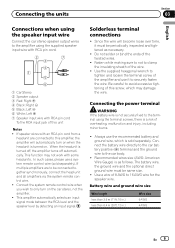
...may not work with RCA pin cord To the RCA input jack of this screw, which is a risk of this unit Notes ! Use a wire of the wire. ! If speaker wires with an RCA pin cord from a headunit are to be same size. ! Solderless terminal connections ! Fasten while making sure to not to ...clamp the insulating sheath of 8 AWG to 16 AWG wire for the speaker wire. In such cases, please use it must be connected together synchronously, connect the head unit and all amplifiers via the system remote control...
...may not work with RCA pin cord To the RCA input jack of this screw, which is a risk of this unit Notes ! Use a wire of the wire. ! If speaker wires with an RCA pin cord from a headunit are to be same size. ! Solderless terminal connections ! Fasten while making sure to not to ...clamp the insulating sheath of 8 AWG to 16 AWG wire for the speaker wire. In such cases, please use it must be connected together synchronously, connect the head unit and all amplifiers via the system remote control...
Owner's Manual
Page 10
... to the positive (+) battery terminal. 2 1 3 1 Positive (+) terminal 2 Battery wire (sold separately) Each amplifier must be separately fused at 100 A (GM-D8601) / 150 A (GM-D9601). 2 Use wire cutters or a utility knife to strip the end of the battery wire, ground wire and system remote control wire to short-circuit the wire damaging it , take care not to expose about 10...
... to the positive (+) battery terminal. 2 1 3 1 Positive (+) terminal 2 Battery wire (sold separately) Each amplifier must be separately fused at 100 A (GM-D8601) / 150 A (GM-D9601). 2 Use wire cutters or a utility knife to strip the end of the battery wire, ground wire and system remote control wire to short-circuit the wire damaging it , take care not to expose about 10...
Owner's Manual
Page 11
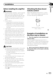
...× 18 mm (5/32 in. × 3/4 in.)) into the screw holes and push on the floor mat or chassis 1 Place the amplifier in : - If any wire. Places where it could injure the driver or passengers if the vehicle stops suddenly. - ver, such as short-circuit may damage internal parts of the... the carpet or directly on the car model. Do not install in the desired installation location. Install tapping screws in fire. ! When drilling to prevent wires from being cut by vibration of the car, which can be located. 2 Drill 2.5 mm (3/32 in front of the ampli- fier, ensure the following ...
...× 18 mm (5/32 in. × 3/4 in.)) into the screw holes and push on the floor mat or chassis 1 Place the amplifier in : - If any wire. Places where it could injure the driver or passengers if the vehicle stops suddenly. - ver, such as short-circuit may damage internal parts of the... the carpet or directly on the car model. Do not install in the desired installation location. Install tapping screws in fire. ! When drilling to prevent wires from being cut by vibration of the car, which can be located. 2 Drill 2.5 mm (3/32 in front of the ampli- fier, ensure the following ...
Owner's Manual
Page 13
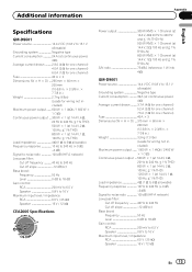
Additional information Appendix English Specifications GM-D8601 Power source 14.4 V DC (10.8 V to 15.1 V allowable) Grounding system Negative type Current consumption 24 A (at continuous power, 4 W) Average current drawn ......... 2.9 A (4 W ...Fuse 40 A × 3 Dimensions (W × H × D) ... 315 mm × 60 mm × 200 mm (12-3/8 in. × 2-3/8 in. × 7-7/8 in.) Weight 3.3 kg (7.3 lbs) (Leads for wiring not included) Maximum power output ....... 1 000 W × 1 (4 W) / 2 400 W × 1 (1 W) Continuous power output ... 500 W × 1 (at 14.4 V, 4 W, 20 Hz to 240 Hz, &#...
Additional information Appendix English Specifications GM-D8601 Power source 14.4 V DC (10.8 V to 15.1 V allowable) Grounding system Negative type Current consumption 24 A (at continuous power, 4 W) Average current drawn ......... 2.9 A (4 W ...Fuse 40 A × 3 Dimensions (W × H × D) ... 315 mm × 60 mm × 200 mm (12-3/8 in. × 2-3/8 in. × 7-7/8 in.) Weight 3.3 kg (7.3 lbs) (Leads for wiring not included) Maximum power output ....... 1 000 W × 1 (4 W) / 2 400 W × 1 (1 W) Continuous power output ... 500 W × 1 (at 14.4 V, 4 W, 20 Hz to 240 Hz, &#...


