Service Manual
Page 1
CRT3371 For details, refer to "Important check points for good servicing". DEC. 2004 Printed in Japan PIONEER CORPORATION 4-1, Meguro 1-Chome, Meguro-ku, Tokyo 153-8654, Japan PIONEER ELECTRONICS (USA) INC. PIONEER EUROPE NV Haven 1087 Keetberglaan 1, 9120 Melsele, Belgium PIONEER ELECTRONICS ASIACENTRE PTE.LTD. 253 Alexandra Road, #04-01, Singapore 159936 C PIONEER CORPORATION 2004 K-ZZB. Service Manual GM-7100M/XU/EW MONO POWER AMPLIFIER GM-7100M/XU/EW GM-7100M/XU/UC GM-7100M/XU/ES GM-7100M/XU/CN GM-7150M/XU/UC ORDER NO. P.O.Box 1760, Long Beach, CA 90801-1760 U.S.A.
CRT3371 For details, refer to "Important check points for good servicing". DEC. 2004 Printed in Japan PIONEER CORPORATION 4-1, Meguro 1-Chome, Meguro-ku, Tokyo 153-8654, Japan PIONEER ELECTRONICS (USA) INC. PIONEER EUROPE NV Haven 1087 Keetberglaan 1, 9120 Melsele, Belgium PIONEER ELECTRONICS ASIACENTRE PTE.LTD. 253 Alexandra Road, #04-01, Singapore 159936 C PIONEER CORPORATION 2004 K-ZZB. Service Manual GM-7100M/XU/EW MONO POWER AMPLIFIER GM-7100M/XU/EW GM-7100M/XU/UC GM-7100M/XU/ES GM-7100M/XU/CN GM-7150M/XU/UC ORDER NO. P.O.Box 1760, Long Beach, CA 90801-1760 U.S.A.

Service Manual
Page 2
... product contains lead in this manual. Improperly performed repairs can adversely affect the safety and reliability of California to perform the repair of this manual. C D E F 2 GM-7100M/XU/EW 1 2 3 4 If you should keep the safety during servicing by this product properly and safely, you are known to do -it-yourselfer. Service Precaution...
... product contains lead in this manual. Improperly performed repairs can adversely affect the safety and reliability of California to perform the repair of this manual. C D E F 2 GM-7100M/XU/EW 1 2 3 4 If you should keep the safety during servicing by this product properly and safely, you are known to do -it-yourselfer. Service Precaution...
Service Manual
Page 3
.... 6 Make sure the wiring cables are equal to follow this method especially if it with the below symbol. Please be sure to the specified substance. F GM-7100M/XU/EW 3 5 6 7 8 5 6 7 8 [Important Check Points for Good Servicing] A In this manual, procedures that must be performed during transit, the shipping mode should be set to...
.... 6 Make sure the wiring cables are equal to follow this method especially if it with the below symbol. Please be sure to the specified substance. F GM-7100M/XU/EW 3 5 6 7 8 5 6 7 8 [Important Check Points for Good Servicing] A In this manual, procedures that must be performed during transit, the shipping mode should be set to...
Service Manual
Page 4
1 2 3 4 A CONTENTS SAFETY INFORMATION 2 1. PCB CONNECTION DIAGRAM 20 4.1 AMP UNIT 20 4.2 REMOTE CONTROL UNIT 24 5. EXPLODED VIEWS AND PARTS LIST 6 2.1 PACKING 6 2.2 EXTERIOR 8 3. SPECIFICATIONS 5 2. ADJUSTMENT 28 7. SCHEMATIC DIAGRAM 12 3.1 OVERALL CONNECTION DIAGRAM(GUIDE PAGE) ....12 3.2 REMOTE CONTROL UNIT 18 B 4. GENERAL INFORMATION 29 7.1 DIAGNOSIS 29 7.1.1 DISASSEMBLY 29 7.1.2 CONNECTOR FUNCTION DESCRIPTION ......31 8. OPERATIONS 32 C D E F 4 GM-7100M/XU/EW 1 2 3 4 ELECTRICAL PARTS LIST 25 6.
1 2 3 4 A CONTENTS SAFETY INFORMATION 2 1. PCB CONNECTION DIAGRAM 20 4.1 AMP UNIT 20 4.2 REMOTE CONTROL UNIT 24 5. EXPLODED VIEWS AND PARTS LIST 6 2.1 PACKING 6 2.2 EXTERIOR 8 3. SPECIFICATIONS 5 2. ADJUSTMENT 28 7. SCHEMATIC DIAGRAM 12 3.1 OVERALL CONNECTION DIAGRAM(GUIDE PAGE) ....12 3.2 REMOTE CONTROL UNIT 18 B 4. GENERAL INFORMATION 29 7.1 DIAGNOSIS 29 7.1.1 DISASSEMBLY 29 7.1.2 CONNECTOR FUNCTION DESCRIPTION ......31 8. OPERATIONS 32 C D E F 4 GM-7100M/XU/EW 1 2 3 4 ELECTRICAL PARTS LIST 25 6.
Service Manual
Page 5
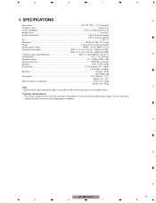
... this value when working out total current drawn by this unit when an audio signal is nearly the maximum current drawn by multiple power amplifiers. D E F GM-7100M/XU/EW 5 5 6 7 8 SPECIFICATIONS A Power source ...14.4 V DC (10.8 - 15.1 V allowable) Grounding system ...Negative type Current consumption ...33.0 A (at continuous power, 4 Ω) Backup current ...3 mA or...
... this value when working out total current drawn by this unit when an audio signal is nearly the maximum current drawn by multiple power amplifiers. D E F GM-7100M/XU/EW 5 5 6 7 8 SPECIFICATIONS A Power source ...14.4 V DC (10.8 - 15.1 V allowable) Grounding system ...Negative type Current consumption ...33.0 A (at continuous power, 4 Ω) Backup current ...3 mA or...
Service Manual
Page 6
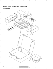
1 2 3 4 A 2. EXPLODED VIEWS AND PARTS LIST 2.1 PACKING B 8 1 C 11 3 6 5 54 7 2 12 8 D 9 E F 6 1 10 GM-7100M/XU/EW 2 3 4
1 2 3 4 A 2. EXPLODED VIEWS AND PARTS LIST 2.1 PACKING B 8 1 C 11 3 6 5 54 7 2 12 8 D 9 E F 6 1 10 GM-7100M/XU/EW 2 3 4
Service Manual
Page 7
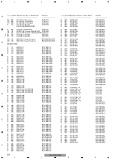
...the instructions in our Master Spare Parts List. - For the applying amount of the part. Owner's Manual Part No. A - Description GM-7150M/XU/UC 1 Cord Assy CDE7736 2 Cord Assy CDE7804 3 Screw Assy CEA4836 4 Screw BYC30P100FZK D 5 Screw BYC40P180FZK * 6 Polyethylene Sheet...Spanish CRD3923 English, Spanish CRD3924 Arabic, Portuguese(B) F CRB2042 Traditional Chinese GM-7100M/XU/EW 7 5 6 7 8 PACKING SECTION PARTS LIST Mark No. GM-7100M/XU/EW GM-7100M/XU/UC GM-7100M/XU/ES GM-7100M/XU/CN CDE7736 CDE7736 CDE7736 CDE7736 CDE7804 Not used Not used Not ...
...the instructions in our Master Spare Parts List. - For the applying amount of the part. Owner's Manual Part No. A - Description GM-7150M/XU/UC 1 Cord Assy CDE7736 2 Cord Assy CDE7804 3 Screw Assy CEA4836 4 Screw BYC30P100FZK D 5 Screw BYC40P180FZK * 6 Polyethylene Sheet...Spanish CRD3923 English, Spanish CRD3924 Arabic, Portuguese(B) F CRB2042 Traditional Chinese GM-7100M/XU/EW 7 5 6 7 8 PACKING SECTION PARTS LIST Mark No. GM-7100M/XU/EW GM-7100M/XU/UC GM-7100M/XU/ES GM-7100M/XU/CN CDE7736 CDE7736 CDE7736 CDE7736 CDE7804 Not used Not used Not ...
Service Manual
Page 9
... Cover See Contrast table(2) 46 Knob Unit 47 Spring 48 Remote Control Assy 49 Sheet See Contrast table(2) See Contrast table(2) See Contrast table(2) CNM9571 D E F GM-7100M/XU/EW 9 5 6 7 8 Description Part No. 1 Screw 2 Screw 3 Screw 4 Screw 5 Screw BBZ30P060FTC BBZ30P080FZK BBZ30P100FZK BBZ30P120FTC BSZ30P050FZK * 6 Badge 7 Screw 8 Case 9 Panel 10 Panel See Contrast table(2) CBA1810...
... Cover See Contrast table(2) 46 Knob Unit 47 Spring 48 Remote Control Assy 49 Sheet See Contrast table(2) See Contrast table(2) See Contrast table(2) CNM9571 D E F GM-7100M/XU/EW 9 5 6 7 8 Description Part No. 1 Screw 2 Screw 3 Screw 4 Screw 5 Screw BBZ30P060FTC BBZ30P080FZK BBZ30P100FZK BBZ30P120FTC BSZ30P050FZK * 6 Badge 7 Screw 8 Case 9 Panel 10 Panel See Contrast table(2) CBA1810...
Service Manual
Page 10
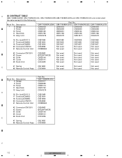
... Spring CBL1692 Not used Not used Not used 48 Remote Control Assy CXC4064 Not used Not used Not used Mark No. Mark No. 1 2 3 4 A (2) CONTRAST TABLE GM-7100M/XU/EW, GM-7100M/XU/UC, GM-7100M/XU/ES,GM-7100M/XU/CN and GM-7150M/XU/UC are constructed the same except for the following: Part No.
... Spring CBL1692 Not used Not used Not used 48 Remote Control Assy CXC4064 Not used Not used Not used Mark No. Mark No. 1 2 3 4 A (2) CONTRAST TABLE GM-7100M/XU/EW, GM-7100M/XU/UC, GM-7100M/XU/ES,GM-7100M/XU/CN and GM-7150M/XU/UC are constructed the same except for the following: Part No.
Service Manual
Page 12
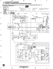
...) 0dB +18.3dBs +17.5dBs LPF 0dB -1.7dB ~ -32.0dB 0dB or +12dB or +6dB ( or +9 +17.5dBs -15dBs B GAIN A BASS BOOST A B CN1351 C -0.8dB D E F A 12 GM-7100M/XU/EW 1 2 3 4 Therefore, when replacing, be sure to refer to use parts of the part. 1 2 3 4 3. Symbol indicates a capacitor. No differentiation is made between chip resistors...
...) 0dB +18.3dBs +17.5dBs LPF 0dB -1.7dB ~ -32.0dB 0dB or +12dB or +6dB ( or +9 +17.5dBs -15dBs B GAIN A BASS BOOST A B CN1351 C -0.8dB D E F A 12 GM-7100M/XU/EW 1 2 3 4 Therefore, when replacing, be sure to refer to use parts of the part. 1 2 3 4 3. Symbol indicates a capacitor. No differentiation is made between chip resistors...
Service Manual
Page 14
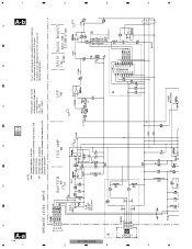
... MAX) A 0dB +18.3dBs +17.5dBs 0dB LPF A -1.7dB ~ -32.0dB 0dB or +12dB or +6dB ( or +9dB) +17.5dBs -15dBs -2.6dBs B GAIN BASS BOOST GM-7100M/XU/EW 3 3 B CN1351 1 4 4 -0.8dB
... MAX) A 0dB +18.3dBs +17.5dBs 0dB LPF A -1.7dB ~ -32.0dB 0dB or +12dB or +6dB ( or +9dB) +17.5dBs -15dBs -2.6dBs B GAIN BASS BOOST GM-7100M/XU/EW 3 3 B CN1351 1 4 4 -0.8dB

Service Manual
Page 20
gram. 2.Viewpoint of PCB diagrams Connector Capacitor SIDE A B SIDE B P.C.Board Chip Part SPEAKER OUTPUT SPEAKER OUTPUT C POWER SUPPLY D E F A 20 1 3 2 1 3 2 1 3 2 1 3 2 1 3 2 1 3 2 1 GM-7100M/XU/EW 2 3 4 1 2 3 4 4. PCB CONNECTION DIAGRAM 4.1 AMP UNIT A NOTE FOR PCB DIAGRAMS 1.The parts mounted on this PCB A AMP UNIT include all necessary parts for respective destinations, be sure to check with the schematic dia- For further information for several destination.
gram. 2.Viewpoint of PCB diagrams Connector Capacitor SIDE A B SIDE B P.C.Board Chip Part SPEAKER OUTPUT SPEAKER OUTPUT C POWER SUPPLY D E F A 20 1 3 2 1 3 2 1 3 2 1 3 2 1 3 2 1 3 2 1 GM-7100M/XU/EW 2 3 4 1 2 3 4 4. PCB CONNECTION DIAGRAM 4.1 AMP UNIT A NOTE FOR PCB DIAGRAMS 1.The parts mounted on this PCB A AMP UNIT include all necessary parts for respective destinations, be sure to check with the schematic dia- For further information for several destination.
Service Manual
Page 25
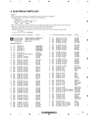
...IC (B,274,173) IC NJM4558MD NJM4558MD NJM4558MD NJM4558MD NJM4558MD IC 651 IC 701 IC 901 Q 201 Q 202 (A,168,99) IC (B,271,142) IC(EW,7150M/UC) (B,159,67) IC (B,249,140) Transistor (B,252,137) Transistor PA2027A MAX309ESE UPC494GS 2SC4081 2SC4081 Q 203 Q 551 Q 552 Q 553 Q 554 (B,... 50µH CTH1323 L 951 (A,69,166) Choke Coil 320µH CTH1326 L 952 (A,41,166) Choke Coil 320µH T 901 (A,101,86) Transformer CTH1326 CTT1123 F GM-7100M/XU/EW 25 5 6 7 8 Meaning of the corresponding PC board. 5 6 7 8 5. The > mark found on the point (face A, 91 of x-axis, and...
...IC (B,274,173) IC NJM4558MD NJM4558MD NJM4558MD NJM4558MD NJM4558MD IC 651 IC 701 IC 901 Q 201 Q 202 (A,168,99) IC (B,271,142) IC(EW,7150M/UC) (B,159,67) IC (B,249,140) Transistor (B,252,137) Transistor PA2027A MAX309ESE UPC494GS 2SC4081 2SC4081 Q 203 Q 551 Q 552 Q 553 Q 554 (B,... 50µH CTH1323 L 951 (A,69,166) Choke Coil 320µH CTH1326 L 952 (A,41,166) Choke Coil 320µH T 901 (A,101,86) Transformer CTH1326 CTT1123 F GM-7100M/XU/EW 25 5 6 7 8 Meaning of the corresponding PC board. 5 6 7 8 5. The > mark found on the point (face A, 91 of x-axis, and...
Service Manual
Page 26
... RS1/16S472J RS1/16S682J RS1/16S682J RS1/16S103J RS1/16S222J RS1/16S472J RS1/16S103J RS1/16S103J RS1/16S473J RD1/4PU222J RS1/16S1R0J RS1/16S104J 26 GM-7100M/XU/EW 1 2 3 4 1 2 3 4 =====Circuit Symbol and No.===Part Name Part No.
... RS1/16S472J RS1/16S682J RS1/16S682J RS1/16S103J RS1/16S222J RS1/16S472J RS1/16S103J RS1/16S103J RS1/16S473J RD1/4PU222J RS1/16S1R0J RS1/16S104J 26 GM-7100M/XU/EW 1 2 3 4 1 2 3 4 =====Circuit Symbol and No.===Part Name Part No.
Service Manual
Page 28
E F 28 GM-7100M/XU/EW 1 2 3 4 ADJUSTMENT There is no information to be shown in this chapter. 1 2 3 4 =====Circuit Symbol and No.===Part Name Part No. A C 955 (A,134,194) C 956 (A,... (A,146,182) CQHA102J2A CEAT221M16 CEANP470M16 CFTNA103J50 CEAT471M50(P45) C 992 (A,121,180) C 993 (A,136,176) C 994 (A,130,176) CEAT471M50(P45) CQHA102J2A CQHA102J2A B Unit Number : CWM9848(EW,7150M/UC) Unit Name : Remote Control Unit MISCELLANEOUS Q 1351 (B,21,23) Transistor Q 1352 (B,22,6) Transistor C D 1351 (B,12,25) Diode D 1352 (B,16,6) Diode D 1366 (B,21,11) Diode...
E F 28 GM-7100M/XU/EW 1 2 3 4 ADJUSTMENT There is no information to be shown in this chapter. 1 2 3 4 =====Circuit Symbol and No.===Part Name Part No. A C 955 (A,134,194) C 956 (A,... (A,146,182) CQHA102J2A CEAT221M16 CEANP470M16 CFTNA103J50 CEAT471M50(P45) C 992 (A,121,180) C 993 (A,136,176) C 994 (A,130,176) CEAT471M50(P45) CQHA102J2A CQHA102J2A B Unit Number : CWM9848(EW,7150M/UC) Unit Name : Remote Control Unit MISCELLANEOUS Q 1351 (B,21,23) Transistor Q 1352 (B,22,6) Transistor C D 1351 (B,12,25) Diode D 1352 (B,16,6) Diode D 1366 (B,21,11) Diode...
Service Manual
Page 29
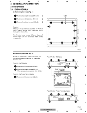
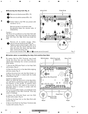
... Removing the Panel (Fig. 2) Panels are used for two sides individually, one for the RCA side and the other for the Power Terminal side 3 3 3 3 3 3 F Fig. 2 GM-7100M/XU/EW 29 5 6 7 8 Case 2 Remove six white screws (M3 x 6). 3 Remove four black screws (M3 x 5). 2 2 2 Caution) 3 When you disassemble/re-assemble the Product with it placed...
... Removing the Panel (Fig. 2) Panels are used for two sides individually, one for the RCA side and the other for the Power Terminal side 3 3 3 3 3 3 F Fig. 2 GM-7100M/XU/EW 29 5 6 7 8 Case 2 Remove six white screws (M3 x 6). 3 Remove four black screws (M3 x 5). 2 2 2 Caution) 3 When you disassemble/re-assemble the Product with it placed...
Service Manual
Page 30
... Holder with screws. (Fig. 2) 5) Secure the Amp Unit on the Heat Sink with screws. (Fig. 3) F 6) Secure the Panel for the RCA side Stud Fig. 4 30 GM-7100M/XU/EW 1 2 3 4 1 2 3 4 Removing the Amp Unit (Fig. 3) A 1 Remove six black screws (M3 x 10). 2 Remove six white screws (M3 x 12). This means forcibly removing the Amp...
... Holder with screws. (Fig. 2) 5) Secure the Amp Unit on the Heat Sink with screws. (Fig. 3) F 6) Secure the Panel for the RCA side Stud Fig. 4 30 GM-7100M/XU/EW 1 2 3 4 1 2 3 4 Removing the Amp Unit (Fig. 3) A 1 Remove six black screws (M3 x 10). 2 Remove six white screws (M3 x 12). This means forcibly removing the Amp...
Service Manual
Page 32
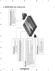
...to the NORMAL position. A 8. When using with an RCA equipped Pioneer car stereo with this power amplifier is switched on the front of 4 V or more, adjust level to the amplifier, see the "Connection Diagram" section. 4 3 2 1 GM-7100M/XU/EW 32 F E Power Indicator The power indicator lights when...select a bass boost level from 40 to 240 Hz. Bass Boost Control You can select a cut off frequency from 0, 6, 9 and 12 dB. OPERATIONS (GM-7100M/XU/EW) 4 3 2 1 If the sound distorts when the volume is turned up , turn gain control on . D C B BFC (Beat Frequency Control...
...to the NORMAL position. A 8. When using with an RCA equipped Pioneer car stereo with this power amplifier is switched on the front of 4 V or more, adjust level to the amplifier, see the "Connection Diagram" section. 4 3 2 1 GM-7100M/XU/EW 32 F E Power Indicator The power indicator lights when...select a bass boost level from 40 to 240 Hz. Bass Boost Control You can select a cut off frequency from 0, 6, 9 and 12 dB. OPERATIONS (GM-7100M/XU/EW) 4 3 2 1 If the sound distorts when the volume is turned up , turn gain control on . D C B BFC (Beat Frequency Control...


