Service Manual
Page 4
ELECTRICAL PARTS LIST 25 6. ADJUSTMENT 28 7. PCB CONNECTION DIAGRAM 20 4.1 AMP UNIT 20 4.2 REMOTE CONTROL UNIT 24 5. GENERAL INFORMATION 29 7.1 DIAGNOSIS 29 7.1.1 DISASSEMBLY 29 7.1.2 CONNECTOR FUNCTION DESCRIPTION ......31 8. SPECIFICATIONS 5 2. EXPLODED VIEWS AND PARTS LIST 6 2.1 PACKING 6 2.2 EXTERIOR 8 3. OPERATIONS 32 C D E F 4 GM-7100M/XU/EW 1 2 3 4 SCHEMATIC DIAGRAM 12 3.1 OVERALL CONNECTION DIAGRAM(GUIDE PAGE) ....12 3.2 REMOTE CONTROL UNIT 18 B 4. 1 2 3 4 A CONTENTS SAFETY INFORMATION 2 1.
ELECTRICAL PARTS LIST 25 6. ADJUSTMENT 28 7. PCB CONNECTION DIAGRAM 20 4.1 AMP UNIT 20 4.2 REMOTE CONTROL UNIT 24 5. GENERAL INFORMATION 29 7.1 DIAGNOSIS 29 7.1.1 DISASSEMBLY 29 7.1.2 CONNECTOR FUNCTION DESCRIPTION ......31 8. SPECIFICATIONS 5 2. EXPLODED VIEWS AND PARTS LIST 6 2.1 PACKING 6 2.2 EXTERIOR 8 3. OPERATIONS 32 C D E F 4 GM-7100M/XU/EW 1 2 3 4 SCHEMATIC DIAGRAM 12 3.1 OVERALL CONNECTION DIAGRAM(GUIDE PAGE) ....12 3.2 REMOTE CONTROL UNIT 18 B 4. 1 2 3 4 A CONTENTS SAFETY INFORMATION 2 1.
Service Manual
Page 9
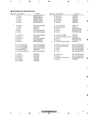
...Screw 8 Case 9 Panel 10 Panel See Contrast table(2) CBA1810 CNB3072 See Contrast table(2) See Contrast table(2) 11 Heat Sink 12 Spacer 13 Amp Unit 14 Screw 15 Screw See Contrast table(2) CNV8256 See Contrast table(2) BBZ30P060FZK BBZ30P080FZK 16 Pin Jack(CN111) 17 Terminal(CN853) 18 Terminal(CN855... See Contrast table(2) 46 Knob Unit 47 Spring 48 Remote Control Assy 49 Sheet See Contrast table(2) See Contrast table(2) See Contrast table(2) CNM9571 D E F GM-7100M/XU/EW 9 5 6 7 8 5 6 7 8 - EXTERIOR SECTION PARTS LIST Mark No. Description 26 Buss Bar 27 Buss Bar 28 Buss Bar...
...Screw 8 Case 9 Panel 10 Panel See Contrast table(2) CBA1810 CNB3072 See Contrast table(2) See Contrast table(2) 11 Heat Sink 12 Spacer 13 Amp Unit 14 Screw 15 Screw See Contrast table(2) CNV8256 See Contrast table(2) BBZ30P060FZK BBZ30P080FZK 16 Pin Jack(CN111) 17 Terminal(CN853) 18 Terminal(CN855... See Contrast table(2) 46 Knob Unit 47 Spring 48 Remote Control Assy 49 Sheet See Contrast table(2) See Contrast table(2) See Contrast table(2) CNM9571 D E F GM-7100M/XU/EW 9 5 6 7 8 5 6 7 8 - EXTERIOR SECTION PARTS LIST Mark No. Description 26 Buss Bar 27 Buss Bar 28 Buss Bar...
Service Manual
Page 10
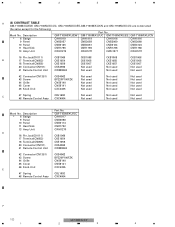
.../XU/EW 1 2 3 4 1 2 3 4 A (2) CONTRAST TABLE GM-7100M/XU/EW, GM-7100M/XU/UC, GM-7100M/XU/ES,GM-7100M/XU/CN and GM-7150M/XU/UC are constructed the same except for the following: Part No. Description * 6 Badge 9 Panel 10 Panel 11 Heat Sink 13 Amp Unit D 16 Pin Jack(CN111) 17 Terminal(CN853) 18 Terminal(CN855) 20...
.../XU/EW 1 2 3 4 1 2 3 4 A (2) CONTRAST TABLE GM-7100M/XU/EW, GM-7100M/XU/UC, GM-7100M/XU/ES,GM-7100M/XU/CN and GM-7150M/XU/UC are constructed the same except for the following: Part No. Description * 6 Badge 9 Panel 10 Panel 11 Heat Sink 13 Amp Unit D 16 Pin Jack(CN111) 17 Terminal(CN853) 18 Terminal(CN855) 20...

Service Manual
Page 20
1 2 3 4 4. For further information for several destination. PCB CONNECTION DIAGRAM 4.1 AMP UNIT A NOTE FOR PCB DIAGRAMS 1.The parts mounted on this PCB A AMP UNIT include all necessary parts for respective destinations, be sure to check with the schematic dia- gram. 2.Viewpoint of PCB diagrams Connector Capacitor SIDE A B SIDE B P.C.Board Chip Part SPEAKER OUTPUT SPEAKER OUTPUT C POWER SUPPLY D E F A 20 1 3 2 1 3 2 1 3 2 1 3 2 1 3 2 1 3 2 1 GM-7100M/XU/EW 2 3 4
1 2 3 4 4. For further information for several destination. PCB CONNECTION DIAGRAM 4.1 AMP UNIT A NOTE FOR PCB DIAGRAMS 1.The parts mounted on this PCB A AMP UNIT include all necessary parts for respective destinations, be sure to check with the schematic dia- gram. 2.Viewpoint of PCB diagrams Connector Capacitor SIDE A B SIDE B P.C.Board Chip Part SPEAKER OUTPUT SPEAKER OUTPUT C POWER SUPPLY D E F A 20 1 3 2 1 3 2 1 3 2 1 3 2 1 3 2 1 3 2 1 GM-7100M/XU/EW 2 3 4
Service Manual
Page 25
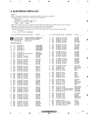
..., 111) IC NJM2068V =====Circuit Symbol and No.===Part Name Part No A Unit Number : CWH1270(EW,7150M/UC) Unit Number : CWH1271(UC,ES,CN) Unit Name : Amp Unit MISCELLANEOUS IC 111 IC 112 IC 141 IC 171 IC 191 (B,294,54) IC (B,275,81)...(A,157,108) Diode ERA15-02VH E D 682 (A,162,111) Diode ERA15-02VH D 701 (B,292,138) Diode(EW,7150M/UC) UDZS16(B) D 703 (B,298,134) Diode(EW,7150M/UC) UDZS16(B) D 951 (B,145,195) Diode UDZS16(B) D 952 (B,123,195) Diode D 957 (A,89,203) ...(A,41,166) Choke Coil 320µH T 901 (A,101,86) Transformer CTH1326 CTT1123 F GM-7100M/XU/EW 25 5 6 7 8
..., 111) IC NJM2068V =====Circuit Symbol and No.===Part Name Part No A Unit Number : CWH1270(EW,7150M/UC) Unit Number : CWH1271(UC,ES,CN) Unit Name : Amp Unit MISCELLANEOUS IC 111 IC 112 IC 141 IC 171 IC 191 (B,294,54) IC (B,275,81)...(A,157,108) Diode ERA15-02VH E D 682 (A,162,111) Diode ERA15-02VH D 701 (B,292,138) Diode(EW,7150M/UC) UDZS16(B) D 703 (B,298,134) Diode(EW,7150M/UC) UDZS16(B) D 951 (B,145,195) Diode UDZS16(B) D 952 (B,123,195) Diode D 957 (A,89,203) ...(A,41,166) Choke Coil 320µH T 901 (A,101,86) Transformer CTH1326 CTT1123 F GM-7100M/XU/EW 25 5 6 7 8
Service Manual
Page 30
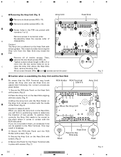
... 8 or more into the two screw holes so as to determine the direction of twelve screws. Re-assembly takes the reverse order of B disassembly. Amp Unit 1 A Screw holes in numerical order. Tighten screws whose length is adhered on the Heat Sink with screws. (Fig. 3) F 6) Secure the... Panel for the RCA side Stud Fig. 4 30 GM-7100M/XU/EW 1 2 3 4 This may break unless the Amp Unit and the Heat Sink are printed with screws. (Fig. 2) RCA Holder RCA Terminal (CN111) Amp Unit Move the Amp Unit Stud Heat Sink Panel for the Power Terminal side in place...
... 8 or more into the two screw holes so as to determine the direction of twelve screws. Re-assembly takes the reverse order of B disassembly. Amp Unit 1 A Screw holes in numerical order. Tighten screws whose length is adhered on the Heat Sink with screws. (Fig. 3) F 6) Secure the... Panel for the RCA side Stud Fig. 4 30 GM-7100M/XU/EW 1 2 3 4 This may break unless the Amp Unit and the Heat Sink are printed with screws. (Fig. 2) RCA Holder RCA Terminal (CN111) Amp Unit Move the Amp Unit Stud Heat Sink Panel for the Power Terminal side in place...


