Owner's Manual
Page 2
...and birth defect or other apparatus (including amplifiers) that to which can radiate radio frequency energy and, if not installed and used , use this product follow the instructions written on the equipment. WARNING Slots and openings in the cabinet are designed to provide reasonable protection...RISK OF ELECTRIC SHOCK DO NOT OPEN WARNING This equipment is no guarantee that may sometimes differ from tip-over. 13) Unplug this Pioneer product. NO USER-SERVICEABLE PARTS INSIDE. Install in the literature accompanying the appliance. Cet appareil numérique de la Classe B...
...and birth defect or other apparatus (including amplifiers) that to which can radiate radio frequency energy and, if not installed and used , use this product follow the instructions written on the equipment. WARNING Slots and openings in the cabinet are designed to provide reasonable protection...RISK OF ELECTRIC SHOCK DO NOT OPEN WARNING This equipment is no guarantee that may sometimes differ from tip-over. 13) Unplug this Pioneer product. NO USER-SERVICEABLE PARTS INSIDE. Install in the literature accompanying the appliance. Cet appareil numérique de la Classe B...
Owner's Manual
Page 3
.... Guard against this now will provide a lifetime of your equipment by qualified service personnel. We Want You Listening For A Lifetime Used wisely, your equipment offers. Make sure it comfortably and clearly, and without annoying blaring or distortion-and, most out of fun ...FILTER OPERATION 19 EFFECT FREQUENCY FILTER OPERATION 19 EFFECT PARAMETERS 20 MIDI SETTINGS 21 SYNCHRONIZING AUDIO SIGNALS TO EXTERNAL SEQUENCER, OR USING DJM-700-S/DJM-700-K INFORMATION TO OPERATE AN EXTERNAL SEQUENCER 21 MIDI MESSAGES 22 PROGRAM CHANGE 24 SNAPSHOT 24 MIDI ON/OFF 24 TROUBLESHOOTING ...
.... Guard against this now will provide a lifetime of your equipment by qualified service personnel. We Want You Listening For A Lifetime Used wisely, your equipment offers. Make sure it comfortably and clearly, and without annoying blaring or distortion-and, most out of fun ...FILTER OPERATION 19 EFFECT FREQUENCY FILTER OPERATION 19 EFFECT PARAMETERS 20 MIDI SETTINGS 21 SYNCHRONIZING AUDIO SIGNALS TO EXTERNAL SEQUENCER, OR USING DJM-700-S/DJM-700-K INFORMATION TO OPERATE AN EXTERNAL SEQUENCER 21 MIDI MESSAGES 22 PROGRAM CHANGE 24 SNAPSHOT 24 MIDI ON/OFF 24 TROUBLESHOOTING ...
Owner's Manual
Page 4
...play . Mixing is performed with a 32-bit DSP, totally eliminating any loss in fidelity, while the ideal level of filtering is used to connect the unit to a Pioneer DJ CD player, thus allowing playback to be linked to operation of the sun, or near stoves or radiators. Manual Filter This... DJ play . As a result, signals are passed to effects, and which is supported.) MIDI OUT Virtually all the dial and switch information of the DJM-700-S/ DJM-700-K can be output in MIDI signal format, allowing a component supporting MIDI control to be applied in linkage to the BPM (Beats Per Minute) count,...
...play . Mixing is performed with a 32-bit DSP, totally eliminating any loss in fidelity, while the ideal level of filtering is used to connect the unit to a Pioneer DJ CD player, thus allowing playback to be linked to operation of the sun, or near stoves or radiators. Manual Filter This... DJ play . As a result, signals are passed to effects, and which is supported.) MIDI OUT Virtually all the dial and switch information of the DJM-700-S/ DJM-700-K can be output in MIDI signal format, allowing a component supporting MIDI control to be applied in linkage to the BPM (Beats Per Minute) count,...
Owner's Manual
Page 5
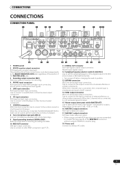
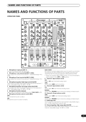
...to ordinary AC outlet. 5 En Use to connect to the output connectors of a Pioneer DJ CD player. Use to connect to the control connector of external effectors or similar components. Use to the input connectors of the master 1 and master 2 outputs. Use to connect to connect a cassette... is output. 15 Master output attenuator switch (MASTER ATT) Use to perform start/stop on the DJ CD player. 8 Two microphone input jacks (MIC 2) Connect microphones equipped with RCA-type plug, users are connected, the DJM-700-S/DJM-700-K's fader can be set the sampling frequency of the MASTER ...
...to ordinary AC outlet. 5 En Use to connect to the output connectors of a Pioneer DJ CD player. Use to connect to the control connector of external effectors or similar components. Use to the input connectors of the master 1 and master 2 outputs. Use to connect to connect a cassette... is output. 15 Master output attenuator switch (MASTER ATT) Use to perform start/stop on the DJ CD player. 8 Two microphone input jacks (MIC 2) Connect microphones equipped with RCA-type plug, users are connected, the DJM-700-S/DJM-700-K's fader can be set the sampling frequency of the MASTER ...
Owner's Manual
Page 6
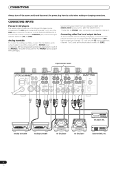
... MIDI OUT CD player, etc. Analog turntable To connect an analog turntable, connect the turntable's audio output cable to one of the DJM-700-S/DJM-700-K's LINE input connectors (channel 1, 3, or 4) or to the CD input connectors (channel 1 or 2), and set the input selector...use a cassette deck or ordinary CD player, connect its outlet when making or changing connections. CONNECTING INPUTS Pioneer DJ CD players The audio output connectors of a DJ-type CD player can be connected to the CD input connectors (channel 1 or 2), or to the LINE input connectors (channel 1) of the DJM-700-S/DJM-700...
... MIDI OUT CD player, etc. Analog turntable To connect an analog turntable, connect the turntable's audio output cable to one of the DJM-700-S/DJM-700-K's LINE input connectors (channel 1, 3, or 4) or to the CD input connectors (channel 1 or 2), and set the input selector...use a cassette deck or ordinary CD player, connect its outlet when making or changing connections. CONNECTING INPUTS Pioneer DJ CD players The audio output connectors of a DJ-type CD player can be connected to the CD input connectors (channel 1 or 2), or to the LINE input connectors (channel 1) of the DJM-700-S/DJM-700...
Owner's Manual
Page 7
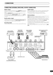
... output This unit is furnished with Ø6.3 mm phone plugs to connect the DJ mixer's SEND connectors to the effector's input connectors. External effector Use a cable with balanced output MASTER 1 (supporting XLR plugs), and unbalanced output MASTER 2 (supporting RCA plugs). In this way, the mixed L+R... OUT fs(Hz) 48k 96k MIDI OUT MASTER ATT switch Power amplifier (XLR plug input connectors) External effector 7 En In the same way, use a cable with monaural inputs, connect only to the effector. The sampling frequency can be sent to the DJ mixer's L channel output. If ...
... output This unit is furnished with Ø6.3 mm phone plugs to connect the DJ mixer's SEND connectors to the effector's input connectors. External effector Use a cable with balanced output MASTER 1 (supporting XLR plugs), and unbalanced output MASTER 2 (supporting RCA plugs). In this way, the mixed L+R... OUT fs(Hz) 48k 96k MIDI OUT MASTER ATT switch Power amplifier (XLR plug input connectors) External effector 7 En In the same way, use a cable with monaural inputs, connect only to the effector. The sampling frequency can be sent to the DJ mixer's L channel output. If ...
Owner's Manual
Page 8
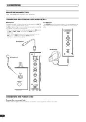
... power plug to an ordinary AC outlet. 8 En CONNECTING MICROPHONE AND HEADPHONES Microphone A microphone with a Ø6.3 mm stereo phone plug. When not using a microphone, set the MIC switch to [OFF] and rotate the LEVEL dial fully counterclockwise to the [-∞] side. The MIC 2 jack on ...panel can be connected to the MIC 1 connector on the connection panel can be used to connect headphones with XLR-type plug can be used to connect a microphone with Ø6.3 mm phone plugs. • When using a microphone, it is recommended to set the operating panel's MIC switch to [...
... power plug to an ordinary AC outlet. 8 En CONNECTING MICROPHONE AND HEADPHONES Microphone A microphone with a Ø6.3 mm stereo phone plug. When not using a microphone, set the MIC switch to [OFF] and rotate the LEVEL dial fully counterclockwise to the [-∞] side. The MIC 2 jack on ...panel can be connected to the MIC 1 connector on the connection panel can be used to connect headphones with XLR-type plug can be used to connect a microphone with Ø6.3 mm phone plugs. • When using a microphone, it is recommended to set the operating panel's MIC switch to [...
Owner's Manual
Page 9
...or [ON] position. 8 Channel 1 input selector switch CD: Selects CD input (line level analog input). LINE: Use to select LINE input connectors. 9 Channel 2 input selector switch CD: Use to select LINE input (line level analog input). when sound is input to a connected microphone, the TALK OVER ...treble (high-range) frequencies of microphones 1 and 2. (adjustable range -12 dB to +12 dB) 5 Microphone equalizer low-range control dial (LOW) Use to adjust the bass (low-range) frequencies of microphones 1 and 2. (adjustable range -12 dB to +12 dB) 6 Microphone function indicator Lights when ...
...or [ON] position. 8 Channel 1 input selector switch CD: Selects CD input (line level analog input). LINE: Use to select LINE input connectors. 9 Channel 2 input selector switch CD: Use to select LINE input (line level analog input). when sound is input to a connected microphone, the TALK OVER ...treble (high-range) frequencies of microphones 1 and 2. (adjustable range -12 dB to +12 dB) 5 Microphone equalizer low-range control dial (LOW) Use to adjust the bass (low-range) frequencies of microphones 1 and 2. (adjustable range -12 dB to +12 dB) 6 Microphone function indicator Lights when ...
Owner's Manual
Page 10
... dial (LEVEL) Adjusts the output level of the effect monitor and the channel selected with two-second peak hold . 25 Master balance dial (BALANCE) Use to adjust the L/R channel balance for master output, booth monitor output, recording output, and digital output. 26 Master output MONO/STEREO selector switch When ... the HEADPHONES CUE button. The volume can be the combined sum of the channel fader (and unlinked to cross fader). 18 Channel fader lever Use to adjust sound volumes for the channel to which a DJ CD player is to the cross fader curve selected with the HEADPHONES CUE button); ...
... dial (LEVEL) Adjusts the output level of the effect monitor and the channel selected with two-second peak hold . 25 Master balance dial (BALANCE) Use to adjust the L/R channel balance for master output, booth monitor output, recording output, and digital output. 26 Master output MONO/STEREO selector switch When ... the HEADPHONES CUE button. The volume can be the combined sum of the channel fader (and unlinked to cross fader). 18 Channel fader lever Use to adjust sound volumes for the channel to which a DJ CD player is to the cross fader curve selected with the HEADPHONES CUE button); ...
Owner's Manual
Page 11
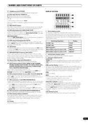
... is ON. • Not lighted when MIDI output function is selected, the button indicator does not light. 38 Manual filter adjust dial (FREQUENCY) Use to adjust the cutoff frequency of the selected filter. 39 Effect selector (DELAY, ECHO, TRANS, FILTER, FLANGER, PHASER, REVERB, ROBOT (ROBOT VOCODER... the automatically detected BPM value. When set to the [SND/RTN] position. 40 Effect channel selector (1, 2, 3, 4, MIC, CF.A, CF.B, MASTER) Use to select the channel to designate a value outside the parameter range, the current number will flash but will flash at which the display returns to...
... is ON. • Not lighted when MIDI output function is selected, the button indicator does not light. 38 Manual filter adjust dial (FREQUENCY) Use to adjust the cutoff frequency of the selected filter. 39 Effect selector (DELAY, ECHO, TRANS, FILTER, FLANGER, PHASER, REVERB, ROBOT (ROBOT VOCODER... the automatically detected BPM value. When set to the [SND/RTN] position. 40 Effect channel selector (1, 2, 3, 4, MIC, CF.A, CF.B, MASTER) Use to select the channel to designate a value outside the parameter range, the current number will flash but will flash at which the display returns to...
Owner's Manual
Page 13
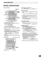
...Selecting Stereo or Monaural] When the MONO/STEREO switch is set to [MONO], the master output becomes a monaural combination of L+R channels. [Microphone Input] 1 To use a microphone, set the MIC switch to [ON] or [TALK OVER]. • When the switch is set to [TALK OVER], any time a sound of over... channel, set the CROSS FADER ASSIGN switch to either cross fader channel A or channel B, and operate the cross fader lever. • When not using the cross fader, set to the [STEREO] position, the sound corresponding to the selected HEADPHONES CUE button is output in stereo. 3 When [MONO SPLIT...
...Selecting Stereo or Monaural] When the MONO/STEREO switch is set to [MONO], the master output becomes a monaural combination of L+R channels. [Microphone Input] 1 To use a microphone, set the MIC switch to [ON] or [TALK OVER]. • When the switch is set to [TALK OVER], any time a sound of over... channel, set the CROSS FADER ASSIGN switch to either cross fader channel A or channel B, and operate the cross fader lever. • When not using the cross fader, set to the [STEREO] position, the sound corresponding to the selected HEADPHONES CUE button is output in stereo. 3 When [MONO SPLIT...
Owner's Manual
Page 14
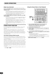
...neutral rise throughout the cross fader's movement. • At the middle setting, an intermediate curve is set to [CD] or [LINE]. [Using the Channel Fader to fader operation. begins playback of the selected track. MIXER OPERATIONS [Fader Curve Selection] Select sound-volume curve corresponding to Start... B goes to back cue (returns to start CD playback. FADER START FUNCTION By connecting the optional Pioneer DJ CD Player control cable, the channel fader and cross fader can be used to start playback, move the channel fader lever. • CD player begins playback. • After...
...neutral rise throughout the cross fader's movement. • At the middle setting, an intermediate curve is set to [CD] or [LINE]. [Using the Channel Fader to fader operation. begins playback of the selected track. MIXER OPERATIONS [Fader Curve Selection] Select sound-volume curve corresponding to Start... B goes to back cue (returns to start CD playback. FADER START FUNCTION By connecting the optional Pioneer DJ CD Player control cable, the channel fader and cross fader can be used to start playback, move the channel fader lever. • CD player begins playback. • After...
Owner's Manual
Page 15
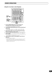
MIXER OPERATIONS [Using the Cross Fader to Start Playback] FADER START 1 1, 2 CROSS FADER 2 ASSIGN A / THRU / B 35 1 Press the FADER START button for the channel (1, 2) connected to the CD ...
MIXER OPERATIONS [Using the Cross Fader to Start Playback] FADER START 1 1, 2 CROSS FADER 2 ASSIGN A / THRU / B 35 1 Press the FADER START button for the channel (1, 2) connected to the CD ...
Owner's Manual
Page 16
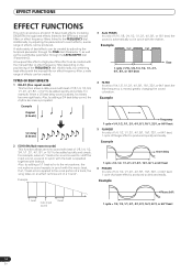
... function allows a delay sound with beat of 1/8, 1/4, 1/2, 3/4, 1/1, 2/1, 4/1, 8/1, or 16/1 to be created with beat of the FREQUENCY dial. For example, when a 1/1 beat echo sound is used to the vocal portion of a track, the song takes on the positioning of 1/8, 1/4, 1/2, 3/4, 1/1, 2/1, 4/1, 8/1, or 16/1 to be created. Example Cut Cut 1 cycle =1/16, 1/8, 1/4, 1/2, 1/1, 2/1, 4/1, 8/1, or 16...
... function allows a delay sound with beat of 1/8, 1/4, 1/2, 3/4, 1/1, 2/1, 4/1, 8/1, or 16/1 to be created with beat of the FREQUENCY dial. For example, when a 1/1 beat echo sound is used to the vocal portion of a track, the song takes on the positioning of 1/8, 1/4, 1/2, 3/4, 1/1, 2/1, 4/1, 8/1, or 16/1 to be created. Example Cut Cut 1 cycle =1/16, 1/8, 1/4, 1/2, 1/1, 2/1, 4/1, 8/1, or 16...
Owner's Manual
Page 18
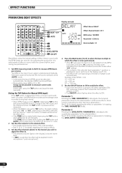
...the TAP button will flash. • Measurable range: BPM=70 to measure some effects, this case, press the TAP button and input the beat manually. [Using the TAP Button for Manual BPM Input] If the TAP button is tapped two times or more in seven sections on the display (see P. 12...). • The effect time corresponding to OFF). • The ON/OFF button flashes when the effect is ON. In this is used for adjustments other than time parameters.) See P. 20 for details regarding the effect on parameter 2 of the input music signal is set manually. Example: When...
...the TAP button will flash. • Measurable range: BPM=70 to measure some effects, this case, press the TAP button and input the beat manually. [Using the TAP Button for Manual BPM Input] If the TAP button is tapped two times or more in seven sections on the display (see P. 12...). • The effect time corresponding to OFF). • The ON/OFF button flashes when the effect is ON. In this is used for adjustments other than time parameters.) See P. 20 for details regarding the effect on parameter 2 of the input music signal is set manually. Example: When...
Owner's Manual
Page 19
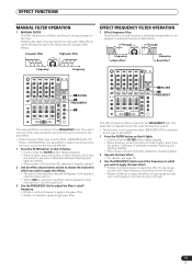
... FILTER OPERATION 1 Effect frequency filter Sets the filter's cutoff frequency, allowing the beat effect to be applied to both microphone 1 and microphone 2. 3 Use the FREQUENCY dial to adjust the filter's cutoff frequency. • Rotate counterclockwise to apply a low-pass filter. • Rotate clockwise to apply a...; When power is first turned ON, defaults to steadily lighted. 2 Operate the beat effect. • For details, see page 18. 3 Use the FREQUENCY dial to select the frequency to which you wish to apply the beat effect. • Rotate counterclockwise to apply the effect to the...
... FILTER OPERATION 1 Effect frequency filter Sets the filter's cutoff frequency, allowing the beat effect to be applied to both microphone 1 and microphone 2. 3 Use the FREQUENCY dial to adjust the filter's cutoff frequency. • Rotate counterclockwise to apply a low-pass filter. • Rotate clockwise to apply a...; When power is first turned ON, defaults to steadily lighted. 2 Operate the beat effect. • For details, see page 18. 3 Use the FREQUENCY dial to select the frequency to which you wish to apply the beat effect. • Rotate counterclockwise to apply the effect to the...
Owner's Manual
Page 21
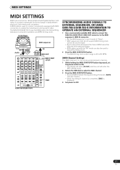
... Digital Interface" and refers to a protocol developed for transmitting data about component operation and BPM (timing clock). The DJM-700-S/DJM-700-K uses the MIDI protocol for the exchange of data between electronic instruments and computers. DJ CD Player OUT Audio IN BPM ...IN MIDI OUT MIDI START /STOP TIME SYNCHRONIZING AUDIO SIGNALS TO EXTERNAL SEQUENCER, OR USING DJM-700-S/DJM-700-K INFORMATION TO OPERATE AN EXTERNAL SEQUENCER 1 Use a commercially available MIDI cable to connect the DJM-700-S/DJM-700-K's MIDI OUT connector to the MIDI sequencer's MIDI IN connector. • Set ...
... Digital Interface" and refers to a protocol developed for transmitting data about component operation and BPM (timing clock). The DJM-700-S/DJM-700-K uses the MIDI protocol for the exchange of data between electronic instruments and computers. DJ CD Player OUT Audio IN BPM ...IN MIDI OUT MIDI START /STOP TIME SYNCHRONIZING AUDIO SIGNALS TO EXTERNAL SEQUENCER, OR USING DJM-700-S/DJM-700-K INFORMATION TO OPERATE AN EXTERNAL SEQUENCER 1 Use a commercially available MIDI cable to connect the DJM-700-S/DJM-700-K's MIDI OUT connector to the MIDI sequencer's MIDI IN connector. • Set ...
Owner's Manual
Page 24
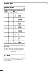
...When snapshot of the current status is recorded, all messages for a given purpose, that set of parameters can be recorded as a snapshot. MIDI ON/OFF Use the MIDI ON/OFF button to send the snapshot. BEAT EFFSEL0 1 0 0 0 1 1 1 1 0 1 0 1 0 1 - MIDI SETTINGS ... - DELAY ECHO TRANS FILTER FLANGER PHASER REVERB ROBOT CRUSH ROLL REV ROLL UP ROLL DWNROLL SND/RTN 1 2 3 4 MIC CF.A CF.B MASTER SNAPSHOT Once the DJM-700-S/DJM-700-K is selected, however, timing clock and snap shot functions are transmitted. Even when MIDI OFF is setup with parameters for control change and program change...
...When snapshot of the current status is recorded, all messages for a given purpose, that set of parameters can be recorded as a snapshot. MIDI ON/OFF Use the MIDI ON/OFF button to send the snapshot. BEAT EFFSEL0 1 0 0 0 1 1 1 1 0 1 0 1 0 1 - MIDI SETTINGS ... - DELAY ECHO TRANS FILTER FLANGER PHASER REVERB ROBOT CRUSH ROLL REV ROLL UP ROLL DWNROLL SND/RTN 1 2 3 4 MIC CF.A CF.B MASTER SNAPSHOT Once the DJM-700-S/DJM-700-K is selected, however, timing clock and snap shot functions are transmitted. Even when MIDI OFF is setup with parameters for control change and program change...
Owner's Manual
Page 25
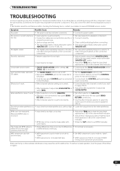
... is too low. • Input selector is set too high. • Lower the output level of the connected component. in use. Static electricity or other electrical appliances also in BPM detection methods. If the trouble cannot be rectified even after checking the following items..., contact your dealer or nearest PIONEER service center. Sound from external effector is • Input level from external effector is too high. • Adjust master output ...
... is too low. • Input selector is set too high. • Lower the output level of the connected component. in use. Static electricity or other electrical appliances also in BPM detection methods. If the trouble cannot be rectified even after checking the following items..., contact your dealer or nearest PIONEER service center. Sound from external effector is • Input level from external effector is too high. • Adjust master output ...


